Vitronics Soltec mySelective 6748 User manual

Installation Guide
mySelective 6748
Version 48.1.0.006
VITRONICS SOLTEC BV
Visit address Innovatiepark 12 - 4906 AA Oosterhout - the Netherlands
Mail address P.O. Box 143 - 4900 AC Oosterhout - the Netherlands
Telephone +31-162-483000
Fax +31-162-483269
www.vitronics-soltec.com

ii
Rights
COPYRIGHT 2010 VITRONICS SOLTEC BV
All rights reserved. No part of this publication may be reproduced, stored in a retrieval system, or transmitted in any form or by any
means, electronic, mechanical, photocopying, recording or otherwise, without the prior written permission of Vitronics Soltec BV.
This publication remains the property of Vitronics Soltec BV and may not be passed, loaned or given to any third party.
Vitronics Soltec BV reserves the right to make changes in design and specifications without notice.
EUROPE
VITRONICS SOLTEC BV VITRONICS SOLTEC GmbH
Innovatiepark 12 Udo-Lermann Str.10
4906 AA Oosterhout 97828 Marktheidenfeld
the Netherlands Germany
Tel. +31-162-483000 Tel. +49-9391-98820
Fax +31-162-483269 Fax +49-9391-988228
AMERICAS
VITRONICS SOLTEC Inc.
2 Marin Way
Stratham, New Hamphire 03885
USA
Tel. +1-603-772-7778
Fax +1-603-772-7776
ASIA PACIFIC
VITRONICS SOLTEC SHANGHAI VITRONICS SOLTEC (SUZHOU) Co. Ltd
Sales Office Manufacturing Plant
858 Zhujiang Lu 858 Zhujiang Lu
Building 2 Building 2
Suzhou New District, China 215129 Suzhou New District, China 215129
Tel. +86-21-5033-7855 Tel. +86-512-6841-3378
Fax +86-21-6360-9449 Fax +86-512-6841-3161
VITRONICS SOLTEC PTE LTD. VITRONICS SOLTEC KOREA
132 Joo Seng Road A-1001, Poonglim Iwant Bldg.
#03-01 Uniplas Building 255-1 Seohyun Dong,
Singapore 368358 Bundang Gu, Seongnam 463-862, Korea
Tel. +65-6484-3010 Tel. +82-31-783-7020
Fax +65-6484-1910 Fax +82-31-783-7021
VITRONICS SOLTEC MALAYSIA
8-2-5 Sunny Point Complex
Jalan Sultan Azlan Shah, Batu Uban,
11700 Penang, Malaysia
Tel. +60-4-658-4227
Fax +60-4-655-4227

Installation Guide mySelective 6748 iii
Preface
During the composition of this manual much attention is given to avoid errors
and mistakes. Also we aimed to give the contents a clear structure.
If during the use of this manual errors or incomplete descriptions are found, or
the reader considers that improvements are necessary to overcome any in-
accuracies, please inform us. We appreciate any comments which will help us to
improve this documentation.
For corrections or clarifications please contact:
1. By mail:
VITRONICS SOLTEC BV
HEAD OFFICE
TECHNICAL PUBLICATIONS
P.O. BOX 143
4900 AC OOSTERHOUT
THE NETHERLANDS
TEL NR. (31) - 162483000
FAX.NR. (31) - 162483285
OR
2. By e-mail:
techpub.nl@vsww.com

iv

Installation Guide mySelective.com v
Ta b l e o f C o n t e n t s
Preface iii
Table of Contents v
1 Installation 1-1
1.1 General . . . . . . . . . . . . . . . . . . . 1-1
1.2 Transport . . . . . . . . . . . . . . . . . . 1-1
1.2.1 Symbols used . . . . . . . . . . . . . . . 1-1
1.2.2 Unpacking . . . . . . . . . . . . . . . . 1-2
1.2.3 Lifting with forklift . . . . . . . . . . . . . 1-3
1.2.4 Centre of Gravity . . . . . . . . . . . . . . 1-3
1.3 Putting in position . . . . . . . . . . . . . . . 1-4
1.3.1 MultiFlux and Robot . . . . . . . . . . . . . 1-4
1.4 Connections . . . . . . . . . . . . . . . . . 1-6
1.4.1 General . . . . . . . . . . . . . . . . . 1-6
1.4.2 Electrical connection . . . . . . . . . . . . . 1-6
1.4.3 Nitrogen connection . . . . . . . . . . . . . 1-6
1.4.4 Exhaust system . . . . . . . . . . . . . . 1-6
1.4.5 Personal computer . . . . . . . . . . . . . 1-6
1.5 Mechanical installation . . . . . . . . . . . . . . 1-7
1.5.1 Measuring conditions . . . . . . . . . . . . . 1-7
1.5.2 Measuring methods . . . . . . . . . . . . . 1-7
1.5.3 Measuring tools . . . . . . . . . . . . . . 1-7
1.6 Mechanical settings . . . . . . . . . . . . . . . 1-8
1.6.1 Frame & Robot . . . . . . . . . . . . . . 1-8
1.6.2 Filling the solderpot . . . . . . . . . . . . . 1-10
1.7 Installation sheet . . . . . . . . . . . . . . . . 1-10
Index vii

vi

ICON DESCRIPTION ICON DESCRIPTION
Only Qualified personnel is allowed to work on the
equipment.
Never eat, drink or smoke while working on the
machine.
Wash thoroughly before eating, drinking or smoking.
High voltages are present on various parts of the sys-
tem.
Before working on the electrical circuit, turn main
power off and block the mainswitch with a padlock.
Always wear heat resistant gloves and protective
clothing when working on the machine.
If possible allow the machine to cool down before
starting working on the machine.
When burned, immerse in cold water immediately.
When the burn is severe, consult a physician as soon
as possible.
Always wear heat resistant gloves and protective
clothing when working on the machine.
If possible allow the machine to cool down before
starting working on the machine
When burned, immerse in cold water immediately.
When the burn is severe, consult a physician as soon
as possible.
No smoking or open fire near the machine.
Be sure a fire-extinguisher is in the surroundings of
the machine.
No smoking or open fire near the machine.
Be sure a fire-extinguisher is in the surroundings of
the machine.
All moving parts of the system, including pulleys,
belts, chains, coolingfans, sprocketwheels, vacuum-
doors and cylinders presents a potential danger.
Be careful with covers and doors. Always pay atten-
tion to opening and closing.
The vapours in the board preparation module are
chemical. When the board is heated, a noxious
vapour will be liberated. This vapour must be
extracted. Also the dust on the surface of the solder-
pot is dangerous when inhaled.
Avoid inhaling this vapours / dust by using mouth
protection.
When working on the machine, always protect your
eyes with safety glasses.
Nitrogen
N2
Follow the safety precautions and procedures
described in the Material Safety Data Sheet of
the Nitrogen supplier.
UPS
Uninterruptible
Power Source
When mainswitch is switched OFF for a longer
period, switch the UPS to OFF.
Signal light RED
- E-stop Active
Signal light GREEN
- Steady = Machine Run,
- Flashing slow = Machine not at setpoint, machine
stop
Signal light ORANGE
- Steady = Overload (outfeed full), Machine will
block,
- Flashing slow = Alarm
- Flashing fast = Critical alarm. Machine will block
LASER RADIATION
Do not stare into beam.
Class 2 Laser product.
Only applicable for Soldering machines
equipped with laser measurement systems.
If these rules are not observed it can cause personal injury and/or damage to the machine
SAFETY RULES
GENERAL INFORMATION

.

Unpacking / Installing mySelective.com CHAPTER 1 1
Installation 1
1.1 GENERAL
Installing only by trained Vitronics Soltec / Agent personnel.
At the end of this chapter an installation sheet is located.
1.2 TRANSPORT
1.2.1 SYMBOLS USED
FIGURE 1.1 SYMBOLS ON PACKAGING
1. Position pallet/box for transport
2. Breakable
3. Keep dry
4. Lift here (labels are placed on
position where forklift should lift)
12 4
3
VERSION April 2008

INSTALLATION
2CHAPTER 1
1.2.2 UNPACKING
The Vitronics Soltec mySelective.com is standard packed on a wooden floor.
1.2.2.1 PACKED IN CRATE
When necessary, the machine is packed in crates (e.g. when shipped).
If packed in crates the following procedure should be followed.
FIGURE 1.2 CRATE
Uncrate order:
1. Take off top cover A.
2. Remove side panels B.
3. Remove front and backcover C.
Use the above figure order A,B,C to uncrate. Other order can result in damaging the machine or
personal injury.
1.2.2.2 PACKED ON AWOODEN FLOOR
Unpacking order:
1. Remove PE-foil.
2. Remove lash cord and take off spare parts.
3. Remove lash cord and foam from machine.
4. Remove machine from wooden floor according to next paragraph.
CB
A

1.2 - TRANSPORT
Unpacking / Installing mySelective.com CHAPTER 1 3
1.2.3 LIFTING WITH FORKLIFT
When the transporting straps are removed, the mySelective.com can be placed on the place the
customer has provided.
To lift and transport the mySelective.com use the positions as shown in the installation sheet at
the end of this document.
FIGURE 1.3 LIFT POSITIONS
1.2.4 CENTRE OF GRAVITY
Depending on the machine configuration, and empty or filled solderpot(s), the Centre of Gravity
will vary. Below 4 examples. Note: these examples are illustrative!
FIGURE 1.4 CENTRE OF GRAVITY

INSTALLATION
4CHAPTER 1
1.3 PUTTING IN POSITION
After the machine is placed on its location, the next steps should be followed.
1.3.1 MULTIFLUX AND ROBOT
FIGURE 1.5 REMOVAL OF TRANSPORT PROTECTIONS
MultiFlux
1. Remove red Transport strips at MultiFlux unit
Robot
1. Remove red Transportstrips at Robot unit.
2. After removing the transport strips, use
mounting materials in plastic bag, to replace the
bolts used for transport strips.

1.3 - PUTTING IN POSITION
Unpacking / Installing mySelective.com CHAPTER 1 5
FIGURE 1.6 MULTIWAVE AND SELECTWAVE
REMOVE THE M8 BOLTS (4X) ON THE
MULTIWAVE
REMOVE THE M8 BOLTS (4X) ON THE
SELECTWAVE

INSTALLATION
6CHAPTER 1
1.4 CONNECTIONS
1.4.1 GENERAL
See for connection specifications the “install sheet” at the end of this chapter.
1.4.2 ELECTRICAL CONNECTION
Only qualified electricians should work on the electrical circuits of the machine.
1. Connect the mains leads in accordance with the diagrams.
Check the Current rotation of the phases. The current rotation of the phases L1, L2, L3 must be
clockwise.
2. Block the mainswitch in the “OFF” position with a padlock to prevent dangerous situations.
1.4.3 NITROGEN CONNECTION
1. Connect the supply hose to the hose connector at the rear outfeed side of the machine.
1.4.4 EXHAUST SYSTEM
One exhaust gauge of 160 mm (6.3”) is provided. This should be connected with the customer’s
exhaust system (not supplied by Vitronics Soltec).
• Inflammable and/or explosive gas might develop in the machine because of the evaporation of
the solvent in the flux.
• An exhaust system that functions well, will bring the gases below the explosion concentra-
tions.
• It is therefore necessary to have a sufficient exhaust in the machine.
• The exhaust system also has to be checked continuously on its well functioning.
• The machine is prepared to interfere in the E-stop circuit of the machine with a potential free
contact of the exhaust system. This contact has to be normally open, and therefore closed
when the exhaust functions well (fail safe).
NEVER USE THE MACHINE WITHOUT THE EXHAUST SYSTEM.
1.4.5 PERSONAL COMPUTER
The complete Personal Computer is packed in boxes for transporting. Unpack all boxes and put
the PC in the machine, and the monitor and keyboard on the PC-arm. Connect all cables.

1.5 - MECHANICAL INSTALLATION
Unpacking / Installing mySelective.com CHAPTER 1 7
1.5 MECHANICAL INSTALLATION
After carefully positioning the machine and allowing for sufficient working space we can continue
installation.
The procedures given here are meant as a directive for measuring and controlling the machine, in
order to guarantee that the machine will run as specified.
During some measurements the robot must be set over the camera position. In that case it is
usefull that the robot will function electrically and mechanically in accordance with the specifica-
tions and with the correct software.
For operating the robot, which is necessary to set the robot over the camera position, see User
manual.
1.5.1 MEASURING CONDITIONS
Before measuring the machine has to come at environmental temperature.
If the measurements have to be done otherwise than with solderpots and preheating in a
'switched off' position, it will be notified in the procedure.
1.5.2 MEASURING METHODS
Unless otherwise specified we will make use of standard available measuring tools.
1.5.3 MEASURING TOOLS
• Machine spirit level 0.1 mm/m scale division.
• Square frame spirit level 0.1 mm/m scale division.
INSTALLATION
8CHAPTER 1
1.6 MECHANICAL SETTINGS
1.6.1 FRAME & ROBOT
During installation the machine frame should be set level and at the correct height.
The frame adjustments in combination with the robot axles should be within a tolerance of 0.2
mm/m when the robot is at camera position.
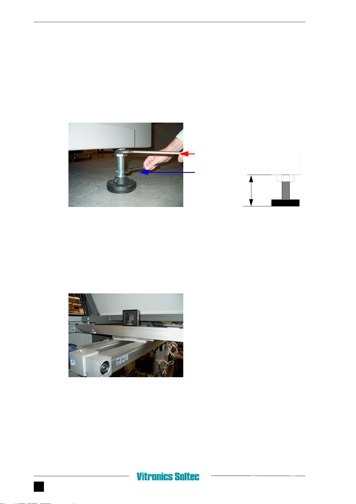
FIGURE 1.7 ADJUSTING WITH LEVELING PADS
1. Release 46 mm nut (A) with open ended spanner.
2. To level the machine, change height leveling pad with 27 mm spanner.
3. Move Robot above camera position.
4. Place spiritlevel on front X-axis.
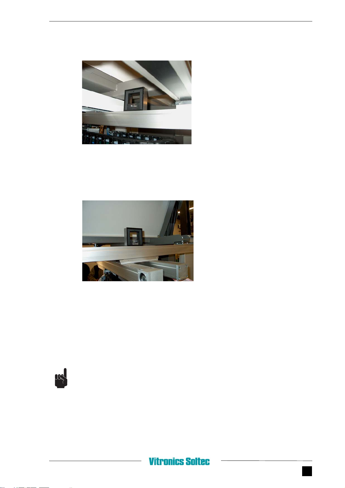
FIGURE 1.8 FRONTSIDE X-AXIS
5. Adjust leveling pads on front side.
46 mm open
27 mm open
A
B
ended spanner
ended spanner
75 -150mm
1.6 - MECHANICAL SETTINGS
Unpacking / Installing mySelective.com CHAPTER 1 9
6. Place spiritlevel on Y-axis
FIGURE 1.9 Y-AXIS
7. Level the machine by adjusting the leveling pads.
8. Control backside X-axis.
FIGURE 1.10 BACKSIDE X-AXIS
9. When machine is leveled, tighten the nuts (A). See Figure 1.7.
Don’t forget to remove the spiritlevel after measuring!
After this procedure the machine is mechanically correct installed.
The machinepoints for camera position, conveyor- and fluxing-stations are factory set.

INSTALLATION
10 CHAPTER 1
1.6.2 FILLING THE SOLDERPOT
There are two different ways to fill the solderpot:
1. Filling with granulated solder.
When granulated solder is used: Fill solderpot equally.
2. Filling with solderbars.
When filled with bars, its impossible to melt them on the heated sides of the solderpot. There-
fore the sumps must be removed.
Make sure the bars are placed against the heated sides of the solderpot.
FIGURE 1.11 MAXIMUM SOLDERLEVEL
During heating up and filling the solderpot, it is advised to use in the direct area of the solderpot
an exhaust system.
Always wear protective clothing & glasses when working on the machine.
1.7 INSTALLATION SHEET
See next pages.
Max solderlevel
SelectWave
Max solderlevel
MultiWave
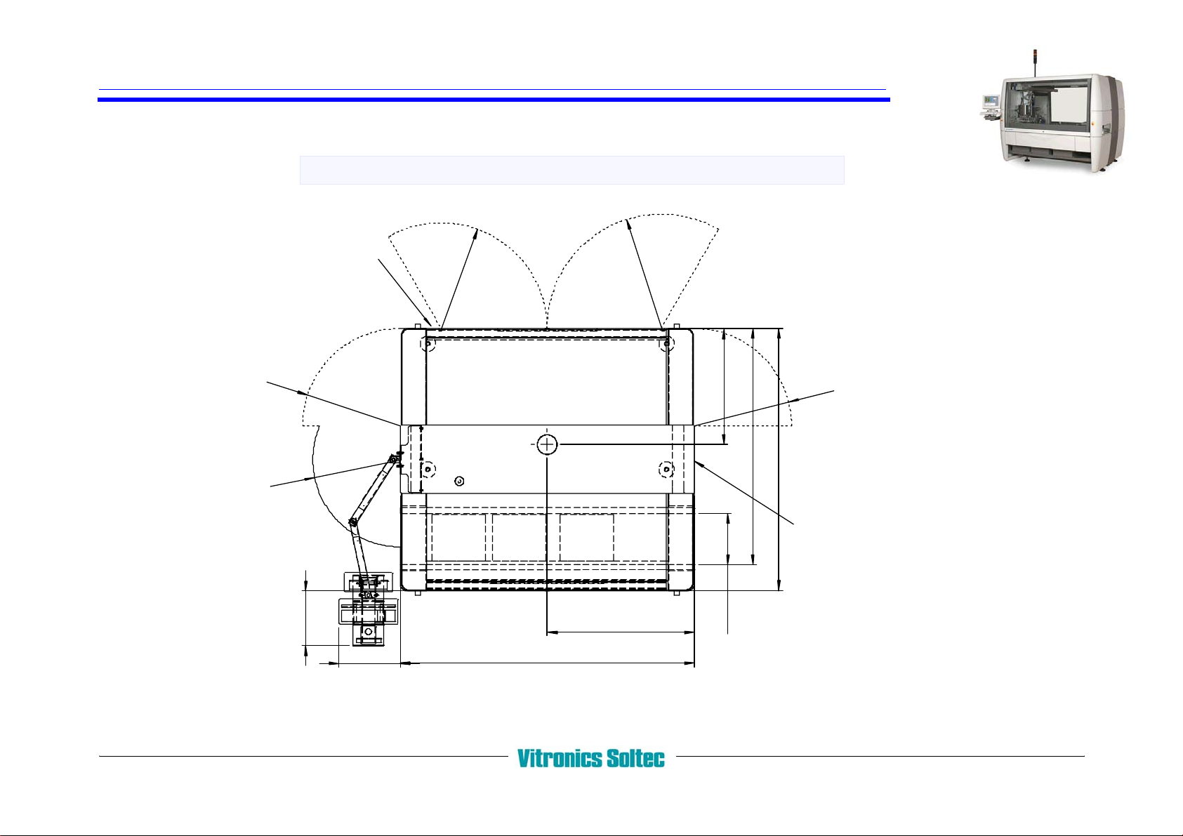
Installation sheet
TOPVIEW 6748
2370 (93.3")
max.410 (16")
ca.500 (20")
1185 (46.6")
R920
R850
R780
R780
R700
ca.400 (15.7")
940 (37")
1903 (74.8")
2110 (83")
N2 connection - 6 bar 20m3/h.
3x400V - 50/60Hz - Max. 37 kVA.
mySelective.com
VERSION April 2008

FRONT AND SIDE VIEW 6748
Transp.height 900 -25/+50 (35.4"-1"/+2")
160 (6.3")
1880 (74")
100 -25/+50 (3.9"-1"/+2") 90 (3.5")
1920 (75.6")
ca.1120 (44")
ca.2600 (102.4")
1013 (39.9")121 (4.8")
LIFTING
DISTANCE BETWEEN FORKS
POINTS.
MINIMUM 800MM-1000MM
LIFT ONLY FROM THIS SIDE !!! (= BACKSIDE OF MACHINE)
UNITS IN MM
UNPACK
MACHINE MACHINE
LIFT MACHINE
PLACE
REMOVE
transport
fastening
materials
Installation sheet mySelective.com
Other manuals for mySelective 6748
1
Table of contents
Other Vitronics Soltec Industrial Equipment manuals


