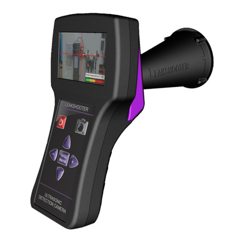
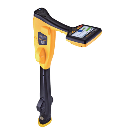
Vivax Metrotech vLoc3 RTK-Pro Instruction Manual

vLoc3 RTK-Pro User Handbook
(English Edition)
Version 1.1
P/N: 4.04.000170


Who Can Use This Equipment
• This equipment must only be used by people suitably trained in the use of pipe and cable locators.
Work-site Safety
• Use your company’s or other applicable safety codes and rules when using this equipment.
• Unless having the required authorization, license, and appropriate training, do not connect to any pipe, cable, or conductor.
• The equipment should not come in contact with corrosive or hazardous chemicals, gases or dust.
•Do not directly connect this equipment to cables or pipes with a potential difference to ground greater than 25V AC.
Equipment Safety
•Do not open the enclosures (housings) of either the transmitter or receiver.
• Place the ground stake firmly in the ground before connecting the cable from the transmitter.
•Do not hold any uninsulated portion of the connection leads & clips when the transmitter is switched on.
Batteries and Environmental Safety
Vivax-Metrotech products use four types of batteries:
•Alkaline batteries
•Ni-MH (Nickel-Metal Hydride) batteries – rechargeable
•Lithium-Ion batteries – rechargeable
•Lithium-Metal batteries – (small non-rechargeable button cells for “clock” applications)
1. Alkaline Batteries (Non-Rechargeable)
• When replacing the alkaline batteries – use only the size and type specified – do not mix battery types (rechargeable and alkaline).
•Do not mix partially discharged and fully charged cells in the same battery pack – do not mix old with new.
•Never attempt to charge alkaline batteries.
2. Nickel-Metal Hydride Batteries (Rechargeable)
•When using rechargeable batteries, use only the correct charging device supplied or specified by the manufacturer. The battery pack or the battery charger will contain
circuitry to manage the charging process – other chargers (even if they have the same connector, polarity, voltage & current rating will not have the same control circuitry
and can cause damage to the product, overheating, and in extreme cases fire or harm to the individual.
•Do not assume that if the plug fits, it is the correct charger – a charger with the correct part number must be used – just because it is a Vivax-Metrotech charger and the
plug fits it does not mean it is the correct charger.
•Before using for the first time, charge rechargeable batteries for six hours. If the rechargeable batteries do not last as long as anticipated at any time, discharge fully and
then charge for six hours.
•Care should be taken when charging batteries – Never repeatedly recharge batteries (or turn the power off & on) without using the instrument. If used with an inverter in
a vehicle – charge the product, unplug the charger, and not charge again until the rechargeable batteries have been used for at least ten minutes. Failure to do this could
result in the overcharging of the battery, which will shorten the battery's life and could, in some circumstances, cause overheating or fire.
•If the product becomes hot during the charging process, immediately unplug the charger, and use the rechargeable batteries for at least ten minutes before recharging. If
this happens, the next time the unit is charged, return it to Vivax-Metrotech for replacement.
•Do not charge batteries for prolonged periods without using the locator for at least ten minutes. Charging for a prolonged period could overcharge the battery, reduce
battery life, and in extreme circumstances, cause damage to the locator and fire.
3. Lithium-Ion Batteries (Rechargeable)
•Lithium-Ion Batteries – some products use Lithium-Ion batteries – the requirements for marking and transportation are still developing. Please contact Vivax-Metrotech
before shipping products containing Lithium-Ion batteries or Lithium-Ion battery packs on their own for any “special instructions.”
4. Lithium-Metal Batteries (Non-Rechargeable)
•Commonly known as “button cells,” these are small – non-rechargeable batteries used to power internal “clocks” within some units (similar to computers). Generally, they
have a life of three to five years.
•Under no circumstances should any attempt be made to charge these batteries.
•Dispose of using your company’s work practice/environmental standards, the prevailing laws, or recognized best practice. Always dispose of batteries responsibly.
5. General Rules regarding Disposal of Batteries
•Never disassemble a battery or battery pack.
•Never dispose of in a fire or water.
•Dispose of batteries following your company’s work practice/environmental standards, the prevailing laws, or recognized best practice. Always dispose of batteries
responsibly.
6. Transportation of Lithium-Ion and Lithium-Metal Batteries
• The Lithium-Ion and Lithium-Metal batteries used in Vivax-Metrotech products meet the required safety standards and include the designated protection circuitry.
•Recent regulation changes require that when batteries with Lithium-Ion and Lithium-Metal batteries are transported, the packaging must include specied warning labels.
•Please contact Vivax-Metrotech Customer Service (USA 1-800-446-3392, International +1-408-734-1400 (USA Pacic Time Zone)) for more details.
•Regulations have also changed regarding the shipping of spare battery packs (battery packs that are not inside a product). There are limitations on the package's weight,
and the packaging must be marked with the appropriate warning labels.
•Please contact Vivax-Metrotech Customer Service (USA 1-800-446-3392, International +1-408-734-1400 (USA Pacic Time Zone)) for more details.
•Vivax-Metrotech vLoc Series 3 products using Lithium-Ion battery are classied as “not restricted.” They can be shipped normally by road/rail/sea & air (passenger & freight
aircraft) without restrictions.
IMPORTANT
Remember – Batteries contain dangerous chemicals – They can be affected by many things such as water ingress or heat – In some
circumstances, they can explode. They also can cause electric shocks!
General Safety & Care Information

Care of Equipment
• Use equipment only as directed in this User Handbook.
•Do not immerse any part of this equipment in water.
• Store in a dry place.
• Keep equipment in the case provided when not in use.
• If left for a prolonged period – remove alkaline batteries.
• Keep the unit clean and free of dust and dirt.
• Protect against excessive heat.
Care when Interpreting the Information provided by the Locator
•Like all locators – this instrument is locating and providing depth and current readings based on electromagnetic signals that radiate from the buried cable or pipe. In most
cases, these signals will enable the locator to pinpoint both position depth and current correctly.
•Beware – in some cases, other factors will distort the electromagnetic fields radiating from cables or pipes being located, resulting in incorrect information.
•Always locate responsibly and use information learned during your training to interpret the information provided by the locator.
•Do not provide information regarding cable or pipe depth to anyone unless authorized to do so by your company.
•Remember that depth measurements are to the center of the electromagnetic field or pipe – In the case of pipes, this may be significantly deeper than the top of the pipe.
American & Canadian Safety Notices
USA
• This transmitter and receiver comply with the general conditions of operation, according to part 15 of the FCC Rules.
οCFR 47 Part 2
οCFR 47 Part 15
•Changes or modications not expressly approved by the manufacturer could void the user’s authority to operate the products.
CANADA
• Equipment is for use by trained operators only and not for general household or consumer use.
•Operation is subject to the following two conditions: (1) this device may not cause interference, and (2) this device must accept any interference that may cause undesired
operation of the device.
EUROPE
•Vivax-Metrotech conrms that the location system is compliant with the relevant provision of European directive 1999/5/EC.
οEN 55011
οEN 61000-4-2: A1 & A2
οEN 61000-4-3
οEN 61000-4-8: A1
οETSI EN 300 330-2
ο ETSI EN 301 489-1
ο ETSI EN 301 489-3
FCC & IC Statement
Please take attention that changes or modication not expressly approved by the party responsible for compliance could void the user’s authority to operate the equipment.
This device complies with Part 15 of the FCC Rules. Operation is subject to the following two conditions:
(1) This device may not cause harmful interference, and
(2) This device must accept any interference received, including interference that may cause undesired operation.
This device complies with Industry Canada licence-exempt RSS standard(s). Operation is subject to the following two conditions:
(1) This device may not cause interference, and
(2) This device must accept any interference, including interference that may cause undesired operation of the device.
Le présent appareil est conforme aux CNR d'Industrie Canada applicables aux appareils radioexempts de licence. L'exploitation est autorisée aux deux conditions suivantes:
(1) l'appareil ne doit pas produire de brouillage, et
(2) l'utilisateur de l'appareil doit accepter tout brouillage radioélectrique subi, même si le brouillage est susceptible d'en compromettre le fonctionnement.
Under Industry Canada regulations, this radio transmitter may only operate using an antenna of a type and maximum (or lesser) gain approved for the transmitter by Industry
Canada. To reduce potential radio interference to other users, the antenna type and its gain should be so chosen that the equivalent isotropically radiated power (e.i.r.p.) is
not more than that necessary for successful communication.
Conformément à la réglementation d'Industrie Canada, le présent émetteur radio peut fonctionner avec une antenne d'un type et d'un gain maximal (ou inférieur) approuvé
pour l'émetteur par Industrie Canada. Dans le but de réduire les risques de brouillage radioélectrique à l'intention des autres utilisateurs, il faut choisir le type d'antenne et son
gain de sorte que la puissance isotrope rayonnée équivalente (p.i.r.e.) ne dépasse pas l'intensité nécessaire à l'établissement d'une communication satisfaisante.
RF exposure info
Occupational use only. This equipment complies with FCC/IC RSS-102 radiation exposure limits set forth for a controlled environment. SAR has been tested with a 10mm
distance.
Usage professionnel uniquement.ce matériel est conforme aux limites de dose d'exposition aux rayonnements, FCC/CNR-102 énoncée dans autre environnement. Le SAR a
été testé avec une distance de 10 mm.

™
Table of Content
1. Service & Support......................................................................................................................................................................1
1.1 Serial Number and Software Revision Number...............................................................................................................1
1.2 Service Centers Closest to You:......................................................................................................................................2
2. vLoc3 RTK-Pro Receiver ...........................................................................................................................................................3
2.1 vLoc3 RTK-Pro Receiver Overview.................................................................................................................................3
2.2 Charging the Receiver Batteries .....................................................................................................................................4
2.3 vLoc3 RTK-Pro Receiver Keypad....................................................................................................................................5
2.4 The vLoc3 Series User Menu..........................................................................................................................................5
2.4.1 Setup - Receiver .................................................................................................................................................6
2.4.2 Setup - Operational .............................................................................................................................................6
2.4.3 Setup - Feature ...................................................................................................................................................7
2.4.4 Setup – Informational ..........................................................................................................................................8
2.5 Self-Test ..........................................................................................................................................................................8
2.6 Warnings and Alerts ........................................................................................................................................................9
2.6.1 Warnings and Alerts Descriptions .......................................................................................................................9
2.6.2 DFT (Discrete Fourier Transform) .......................................................................................................................9
2.7 Setting up the vLoc3 RTK-Pro mapping functions.........................................................................................................10
2.7.1 SIM Set-up ........................................................................................................................................................11
2.7.2 Set up the RTK connections using MyLocator3 ................................................................................................12
2.7.3 Set up the RTK settings in the Locator..............................................................................................................13
2.7.4 Set the VMMap Cloud Settings .........................................................................................................................14
2.8 RTK-Pro Battery Consumption......................................................................................................................................16
2.9 vLoc3 RTK-Pro Locate Modes and Screens .................................................................................................................16
2.9.1 The Classic Screen Status Bar .........................................................................................................................16
2.9.2 The Classic Screen ...........................................................................................................................................17
2.10 Classic Locating Modes (Response).............................................................................................................................17
2.10.1 Peak Response Mode ...........................................................................................................................17
2.10.2 Broad Peak Mode ..................................................................................................................................18
2.10.3 Null Mode ...............................................................................................................................................18
2.10.4 Delta Null ...............................................................................................................................................18
2.10.5 Peak with Arrows Response Mode ........................................................................................................18
2.10.6 Omni Peak Response Mode ..................................................................................................................19
2.10.7 Information Pushbutton (Depth and Current) ..................................................................................................19
2.11 Alternative Locate Screens..........................................................................................................................................20
2.11.1 Vector Configuration Screen............................................................................................................................20
2.11.2 The Transverse Graph Screen ........................................................................................................................21
2.11.3 The Plan View Screen.....................................................................................................................................22
3. Using the vLoc3 RTK-Pro ........................................................................................................................................................24
3.1 Passive Locating ...........................................................................................................................................................24
3.1.1 Detecting Power Signals ...................................................................................................................................24
3.1.2 Detecting Radio Signals....................................................................................................................................25
3.2 Active Locating:- Applying the Transmitter ....................................................................................................................26
3.2.1 Direct Connection..............................................................................................................................................26
3.2.2 Transmitter Signal Clamp (for frequencies above 8kHz)...................................................................................27
3.2.3 Induction (for frequencies above 8kHz) ............................................................................................................29

™
3.3 Locating Active Signals .................................................................................................................................................30
3.4 Searching (sweeping) an Area in the Peak Mode .........................................................................................................31
3.5 Searching (sweeping) an Area in the Omni Peak Mode................................................................................................31
3.6 Tracing a Buried Line ....................................................................................................................................................31
3.7 Depth & Current Measurement .....................................................................................................................................31
3.8 Distorted Fields .............................................................................................................................................................32
3.9 Sonde Location Mode ...................................................................................................................................................33
3.10 Walk Back Feature ........................................................................................................................................................35
3.10.1 VMMap Web Portal .........................................................................................................................................35
3.10.2 Performing an RTK-Pro Walk Back.................................................................................................................37
3.11 Feature Logging ............................................................................................................................................................39
3.11.1 Requirements: .................................................................................................................................................39
3.11.2 Setup and Import of Data Dictionary ...............................................................................................................39
3.11.3 Logging Features.............................................................................................................................................40
3.11.4 Auto Log Feature.............................................................................................................................................41
3.11.5 Feature Logs in VMMap Cloud........................................................................................................................42
4. Data Logging............................................................................................................................................................................43
4.1 How to Create Data Logs ..............................................................................................................................................43
4.2 Pairing the receiver with dataloggers, mobile phones and other external devices........................................................44
4.3 Transferring Data from the vLoc3 Receiver to a Computer...........................................................................................44
4.3.1 The MyLocator3 Desktop App...........................................................................................................................45
4.3.2 MyLocator3’s Basic Operation ..........................................................................................................................45
4.3.2.1 Updates Page ....................................................................................................................................45
4.3.2.2 Application Update .............................................................................................................................46
4.3.2.3 Locator Firmware update ...................................................................................................................46
4.3.3 Toolbar...............................................................................................................................................................47
4.3.4 Feature tabs ......................................................................................................................................................47
4.3.5 Data Logging ...............................................................................................................................................47
4.3.6 Splash Screen ..........................................................................................................................................48
4.3.7 Frequencies Page ......................................................................................................................................50
4.3.8 Menu Settings ...........................................................................................................................................50
4.3.9 Cloud, Internet and RTK Settings ...............................................................................................................51
4.3.10 Advanced Features ...........................................................................................................................................51
4.3.10.1 Supervisor Lockouts.........................................................................................................................51
5. The Loc3 Series Transmitters ..................................................................................................................................................52
5.1 Loc3 Series Transmitter Overview ................................................................................................................................52
5.2 The Transmitter Display.................................................................................................................................................52
5.3 Pushbuttons ..................................................................................................................................................................53
5.3.1 Transmitter Information Pushbuttons ................................................................................................................53
5.3.2 Transmitter Connections Block .........................................................................................................................54
5.4 Transmitter Batteries – Li-ion and Alkaline ....................................................................................................................54
5.5 Charging the Transmitter Battery Tray ..........................................................................................................................55
5.6 Removing and Installing the Battery Tray......................................................................................................................56
5.7 Transmitter Modes.........................................................................................................................................................56
5.7.1 Direct Connection Mode....................................................................................................................................57
5.7.2 Clamp Mode......................................................................................................................................................57
5.7.3 Induction Mode – 5-Watt and 10-Watt Transmitters Only..................................................................................58
5.8 Transmitter Frequencies................................................................................................................................................58
5.8.1 Frequencies and Maximum Power Output........................................................................................................58
5.8.2 Most Used Frequencies (Frequency Selection) Feature...................................................................................59

™
5.8.3 Multi-Frequency Mode for Direct Connection....................................................................................................60
5.9 Transmitter Link (TX-Link) ..................................................................................................................................61
6. Accessories & Options.............................................................................................................................................................64
6.1 Transmitter Signal Clamps ............................................................................................................................................64
6.2 A-Frame Fault Locator...................................................................................................................................................64
6.3 vLoc3-MLA (Marker Locator Adapter) ...........................................................................................................................64
7. Glossary...................................................................................................................................................................................65


™
Page 1 of 66
1 Service & Support
™
1. Service & Support
1.1 Serial Number and Software Revision Number
Always quote your receiver and transmitter model number, serial number, and software revision number when requesting
product support. They can be found as follows: (for reference only).
1
1
1
1 Model & Serial Number
NOTE
Software Revision Number: On both receiver and transmitter, the software revision number is displayed on
the LCD during the startup sequence if the default start screen is used. It can also be found in the “About”
section of the user menu.
Receivers with the SD option installed will show this icon label on the blade where it meets the yellow upper
housing.
Receivers with the Tx-Link option installed will show this icon label on the blade where it meets the yellow
upper housing.
Transmitters with the Tx-Link option installed will show this icon label on the upper corner of the housing.

™
Page 2 of 66
1 Service & Support
1.2 Service Centers Closest to You:
Worldwide Sales Offices and Service Centers
World Headquarters, United States of America
Vivax-Metrotech Corporation
3251 Olcott Street, Santa Clara, CA 95054, USA
T/Free : 1-800-446-3392
Tel : +1-408-734-1400
Fax : +1-408-734-1415
Website : www.vivax-metrotech.com
Canada
Vivax Canada Inc.
41 Courtland Ave Unit 8, Vaughan, ON L4K 3T3, Canada
Tel : +1-289-846-3010
Fax : +1-905-752-0214
Website : www.vivax-metrotech.com
China
Vivax-Metrotech (Shanghai) Ltd.
3/F No.90, Lane 1122 Qinzhou Rd.(N),
Shanghai, China 200233
Tel : +86-21-5109-9980
Fax : +86-21-2281-9562
Website : www.vivax-metrotech.com
Ventas para América Latina
3251 Olcott Street, Santa Clara, CA 95054, USA
T/Free : 1-800-446-3392
Tel : +1-408-734-1400
Fax : +1-408-743-5597
Website : www.vivax-metrotech.com
Central/South America and the Caribbean
Vivax-Metrotech AUS
Unit 1, 176 South Creek Road,
Cromer NSW 2099, Australia
Tel : +61-2-9972-9244
Fax : +61-2-9972-9433
Website : www.vivax-metrotechaus.com
Shanghai Vimap Technology Co. Ltd.
9/F, Building 89, Xinhuiyuan, No.1122 Qinzhou North Road,
Shanghai, China 200233
Tel : 4000-999-811
Website : www.vimap.cn
Vivax-Metrotech SAS
Technoparc ‐1 allée du Moulin Berger,
69130 Ecully, France
Tel : +33(0)4 72 53 03 03
Fax : +33(0)4 72 53 03 13
Website : www.vivax-metrotech.fr
France
Vivax-Metrotech Ltd.
Unit 1, B/C Polden Business Centre,
Bristol Road, Bridgwater,
Somerset, TA6 4AW, UK
Tel : +44(0)1793 822679
Website : www.vivax-metrotech.com
United Kingdom
ChinaAustralasia
International Distributors and Service Centers
Germany
Metrotech Vertriebs GmbH
Am steinernen Kreuz 10a, D-96110 Schesslitz
Tel : +49 954 277 227 43
Website : www.vivax-metrotech.de

™
Page 3 of 66
2 vLoc3 RTK-Pro Receiver
2. vLoc3 RTK-Pro Receiver
2.1 vLoc3 RTK-Pro Receiver Overview
The vLoc3 RTK-Pro is a Precision Location System designed to meet utility companies and their contractors' needs. The
following describes the features and use of the receiver.
This user manual covers the vLoc3 RTK-Pro receiver. In this manual, this receiver may be referred to as vLoc3 series receiver,
receiver or locator.
The vLoc3 Series Receivers are precision locators designed to meet the needs of utility companies and their contractors. The
following describes the features and use of the RTK-Pro receiver.
1
2
3
456 7 8 9
1 vLoc3 RTK-Pro receiver
2 Mini-USB cable
3 Li-ion battery
4 Battery charger
5AA Alkaline batteries
6 Alkaline battery holder
7Power cable for charger
*one of supplied based on geographical location
8 User manual
9Carry case
1
2
9
3
4
6
7
810
5
1 Pushbutton keypad display 6 Mini-USB port for data transfer and software updates
2 Model & serial number label 7 Battery compartment cover
3 Battery retaining cover 8 Accessory socket and charging point
4 AA Alkaline or Li-ion Battery Pack 9Sim card
5 GNSS antenna housing 10 Internal Cellular Antenna

™
Page 4 of 66
2 vLoc3 RTK-Pro Receiver
2.2 Charging the Receiver Batteries
The RTK-Pro can be used with either alkaline batteries or an interchangeable rechargeable battery pack.
The central illuminated section within the battery icon indicates the amount of charge remaining.
• Blue center indicates alkaline batteries.
• Green center indicates rechargeable batteries.
• When batteries are low, the remaining charge section becomes red and will flash.
• Just before shutdown, the following symbol will be shown:
Rechargeable batteries are supplied with a mains charger. This charger is specific to the batteries used. Avoid using other
manufacturers’ chargers as these may damage the battery pack and result in overheating the battery pack.
To charge the rechargeable batteries, rst make sure the pack is inserted in the receiver battery compartment as charging is
done with the battery inside the receiver.
Connect the charger to the charging/accessory socket of the receiver. Connect the charger to the mains and switch it on. The
LED indicator on the charger will illuminate red until the batteries are fully charged, at which time the LED will change to green.
WARNING
Rechargeable batteries are supplied with a main or 12V DC charger. These are specific to the
batteries. Only use the charger that is appropriate for the batteries in the product. If in doubt, call
the Vivax-Metrotech customer service department at +1(800) 446-3392. Failure to use the appropriate
charger could damage the battery pack, locator and, in extreme cases, cause a re.
Avoid charging the unit in extreme temperature conditions. (i.e., below 0ºC and above 45ºC)
Although Vivax-Metrotech batteries include all the required safety-related features, immediately
discontinue the charger and battery pack's use if the battery pack becomes excessively warm. Return
both to where they were purchased for investigation.
Always ensure batteries have at least a partial charge if storing for long periods without use.
Dispose of all batteries following your company procedures and or Federal/State and local
regulations.
Never dismantle batteries, put them in a re, or get wet.

™
Page 5 of 66
2 vLoc3 RTK-Pro Receiver
2.3 vLoc3 RTK-Pro Receiver Keypad
The grey color keys (3, 5, and 6) serve dual functions. You may have to Short Press by momentarily pressing the key or Long
Press by pressing and holding the key until the desired function is shown.
1 2 543
6
vLoc3 Series Keypad
1On/O
2 Reduce sensitivity. (Also scroll up when in User Menu)
3Select frequency
Long press = show the pre-selected frequency table
4Increase sensitivity. (Also scroll down when in User
Menu)
5
Enter Key
Short press = change antenna response when in
classic screen
Long press = change the locate perspective
6
Information and Depth key
Short press = enter the information and logging screen
Long press = enter the User Menu
2.4 The vLoc3 Series User Menu
The user-congurable vLoc3 series receivers can be customized to suit the user’s preferences. The receivers have several
features that can be switched on and o through the user menu.
This section covering the user menu is split into four subsections;
Setup – Covering the settings that are usually chosen and not often changed. Most of these settings apply to the locator's
physical attributes such as language, sound, and measure units.
Operational – Covers the locate screens and locate perspective.
Features – Are optional modes and physical add-ons such as Bluetooth, Marker Locator Adapter, and other options that may
have been ordered.
Informational – Covers the receiver’s conguration, rmware version, and regulatory information.
It is recommended that the Setup section be done rst. It will be easier to nish the receiver's setup if it is done in the native
language.
To enter the user menu, press and hold the “i” key, release the key when in the menu.
Note that where you see this symbol , pressing the enter button gives access to the sub-menu associated with this button.
To exit the menu or sub-menu, press the “i” button.
Where the icon is not shown, the enter button is used to scroll through the options of that feature.
Use the “+” and “-” buttons to scroll up and down through the menu.
Switch on the unit by pressing and holding the On/O key until the start-up screen appears. The start-up screen can be congured
to the user’s preference and is described later in the manual. Otherwise, the start-up screen will default to the one below:
Default start screen

™
Page 6 of 66
2 vLoc3 RTK-Pro Receiver
Menu
About
Speaker Volume
Sound Configuration
Backlight
Frequency
Classic Locate
Locate Perspective
Auto
Menu
Language
Imperial / Metric
Continuous Information
Auto Power Off
Warnings
GPS Source
Satellite Information
English
Meter
Off
Never
Internal
Menu
Transmitter Link
Transmitter Control
Self Test
Cloud
GPS RTK Source
New Survey
Regulatory Labels
Main User Menu
This manual will show three screens, but in the receiver it will be one continuous scrolling screen.
Where you see this Enter button symbol pressing the Enter button will access any associated sub-menus.
While in a sub-menu use the “+” and “- “buttons to scroll through the menu.
To exit the menu or sub-menu, press the “i ” button.
2.4.1 Setup - Receiver
Language – The receiver can be programmed in dierent languages. Repeatedly pressing the Enter key cycles through the list
of available languages.
Speaker Volume – Repeatedly pressing the Enter key raises the speaker volume by three levels and then turns off the
volume. When o is displayed.
Backlight – Press the Enter key to change the backlight intensity to Low, Medium, High, or Auto. The use of the “Auto”
selection is recommended because the receiver has a built-in light sensor that automatically adjusts the backlight intensity to the
surrounding lighting conditions. Auto-selection may improve battery life performance.
Sound Conguration - Changes the sound conguration of the locate modes. Use the Enter key to select AM or FM.
• When in active locate modes:
- Frequency Modulated (FM) Sound pitch changes with signal strength
- Amplitude Modulated (AM) Sound volume changes with signal strength
• When in passive locate modes:
- Radio mode: FM or Real (Sound derived directly from the received signal)
- Power mode: FM or Real
Imperial/Metric – Use the Enter key to select Imperial or Metric measurements for the depth readings.
Continuous Info – The locate screens can display a continuous reading of either depth, current, both, or can be switched o.
Use the Enter key to select your preference.
Auto Power O – The unit can be set to switch o after a set time. Options are 5-minutes, 10-minutes, or Never. Note that
when the accessory A-frame is connected, the timer defaults to “Never.”
2.4.2 Setup - Operational
Frequency - Press the Enter key to enter the Frequency sub-menu. Scroll up and down the table of available frequencies
using the “+” and “-” keys.

™
Page 7 of 66
2 vLoc3 RTK-Pro Receiver
TIP
Simplify the operation of the receiver by selecting only the frequencies applicable to your
applications. To do this use the enter key to check the boxes on the right. Frequencies not checked
will not appear on the locate screen.
Frequency
8.01kHz
8.19kHz
8KFF
8.44kHz
9.50kHz
9.80kHz
9.82kHz
10.0kHz
NOTE
Certain frequencies have an A-frame icon next to them. This icon indicates that these frequencies are
selected to be used with the fault nd A-frame.
Classic Locate – This option is only shown if the menu is entered from the Classic Screen.
Use the enter key to reveal the list of options relating to the Classic Locate mode. Options are:
Classic Locate
Peak
Null
Peak With Arrows
Broad
Delta Null
Omni Directional Peak
Omni Directional Broad
Locate Perspective – Enter this menu to select the graphical format that the locate data will be displayed. These displays are
described further in the manual. The options are:
Locate Perspective
Classic Locate
Vector Locate
Transverse Graph
Plan View
Sonde
GPS Source - Press the “Enter” key to select either Internal or Bluetooth. For the vLoc3 RTK-Pro, this is typically set to
internal.
2.4.3 Setup - Feature
Warnings – Warnings relating to - Shallow cable, Overload, Overhead cable, and Signal Overload. Scroll down to the relevant
warning and use the return button to select or de-select.
Bluetooth Pairing (if installed) – This option allows the receiver to link with external devices such as data loggers and
GPS devices with Bluetooth capability. Press the enter button to enter the Bluetooth pairing routine.
Bluetooth Auto Connect – When this option is enabled, the receiver will automatically connect with any previously paired
Bluetooth device.
Transmitter Link – The Loc3 series transmitters can be remotely operated from the receiver. This option requires the
Transmitter (radio) Link to be installed in both the vLoc3 series receiver and the Loc3 series transmitter. Tx-Link is a factory t
option that must be purchased at the time of ordering. Currently, the Tx-Link feature is only available in the Loc3 series 5-watt
and 10-watt transmitters.

™
Page 8 of 66
2 vLoc3 RTK-Pro Receiver
Transmitter Control – This feature is used to control a transmitter with the Radio Link activated remotely. For more
information, see the section “Remote Operation of the transmitter.”
DFT – Discrete Fourier Transform is a tool to help choose a frequency to apply to the target conductor. The DFT feature will aid
the user with nearby interference that may aect the locate quality.
Cloud – This menu item ties the VMMap Cloud-based app to the RTK-Pro unit. Use this menu item to check the Cloud connection
status. To use the Vivax-Metrotech Cloud-based VMMap app setup an account and register each locator that will use the app.
GPS RTK Source – Enter this option to check RTK connectivity and to select the RTK source.
For more information check the section on Setting up RTK Connectivity.
New Survey – Navigating into this menu and selecting a survey type always causes a new survey to be initiated in the SD
Card Data Logger. This will happen even if it is the same type as the previous log record.
Dierent Survey types can be selected, as shown.
Electric
Gas
Communications
Potable Water
Reclaimed Water
Sewer
Temporary Survey
Proposed Excavation
Oil
2.4.4 Setup – Informational
About – This section holds the data about the locator, such as software revision, calibration data, etc.
Regulatory Labels – This section shows the required FCC ID and IC information. To access this information do the following:
1. Press and hold the Information pushbutton.
2. Use the – and + pushbuttons to highlight “Regulatory Labels.”
3. Press the Enter button when About is highlighted.
Self-Test – The vLoc3 series receivers have a self-test feature that conrms the equipment is t for use and that the calibration
has not drifted from its expected settings.
Satellite Information – Enter this menu item to show all current satellite information.
2.5 Self-Test
The self-test feature must be run in an area free from interference, such as overhead uorescent lighting, large transformers,
etc. Also, check that any nearby transmitters or sondes are switched o.
Select “Self-Test” from the user menu and press the “Return” button. Keep the receiver stationary while the test is running. After
a short while, the test will complete, and the unit will report Passed or Failed.
Self Test: PASSED
110.3
110.3
64.1
110.3
110.3
64.1
Self Test: FAILED
109.6
109.9
64.3
109.7
109.9
64.5
Examples of the self-test results
If the receiver fails the test, try again in an area with less interference. If it continues to fail, return the unit to Vivax-Metrotech or
one of its approved repair centers for investigation.

™
Page 9 of 66
2 vLoc3 RTK-Pro Receiver
2.6 Warnings and Alerts
Warning symbols are accompanied by an audible sound and vibration in the handle unless otherwise configured in the
MyLocator3 desktop app. Warnings can also be switched o in the setup menu.
61.4 32.8kHz24dB
4G
2.6.1 Warnings and Alerts Descriptions
ALERT Alert Description
Signal Overload - is usually caused by operating close to power transformers or being close to a transmitter in
Induction mode. Moving away from the interfering signal will cure the problem.
Shallow Cable - alerts indicate that the locator has detected a possibly less than 15cm (5.9-inch) deep cable.
Proceed with caution.
Swing Alert - indicates that the operator is swinging the locator excessively, resulting in misleading information.
When sweeping the locator across the direction of the line, try to keep it vertical; this will improve its accuracy.
Overhead Cable - alerts indicate that the source of the signal is mainly radiating from above. This alert is usually
caused by the signal traveling along overhead cables.
2.6.2 DFT (Discrete Fourier Transform)
DFT is a tool to assist in choosing a frequency to apply to the target conductor. The DFT feature will aid the user with nearby
interference that may aect the locate quality.
*Note the DFT feature should not solely be used to determine which frequency to apply. ALWAYS
follow the appropriate safety requirements mandated by safety legislation, safety practice, or your
company’s safety procedures when applying a locate frequency to a conductor.
1. To perform a DFT assessment, verify any nearby transmitters are powered off to avoid additional signal frequency
disturbance.
2. Select your preferred frequencies from the frequency menu. These selected frequencies will be assessed in the next few
steps.
Frequency
128Hz
480Hz
491Hz
512Hz
577Hz
815Hz
982Hz
1.02kHz
3. Navigate to the main menu and scroll until you see DFT. Select DFT by pressing the enter key.
4. Once the option is selected, the receiver will automatically assess the user’s preselected frequencies.

™
Page 10 of 66
2 vLoc3 RTK-Pro Receiver
5. The receiver will scan all available frequencies and display a progress bar, and the list of frequencies assessed will be
displayed. The frequency under test is shown on the top line.
Frequency: 8.19kHz
491Hz
512Hz
80 dB
74 dB
6. A numerical value ranging from 0dB to 140dB will be presented next to the frequency list, with 140dB being the least
possible interference detected and 0db with the largest amount of possible interference.
7. The results are ranked from the least interference possible at the top to the largest amount of most possible interference at
the bottom.
8. In this case, the higher the dB number (80dB), the less interference has been detected by the receiver.
Frequency: 491Hz
491Hz
512Hz
8.19kHz
32.8kHz
65.5kHz
131kHz
200kHz
80 dB
74 dB
62 dB
56 dB
49 dB
43 dB
37 dB
* Note - although frequency results appear to have less interference, it still does not make it the best
choice to locate certain utilities. These include but are not limited to a conductor, current output,
resistance, and signal bleed over adjacent utilities.
2.7 Setting up the vLoc3 RTK-Pro mapping functions
Introduction
This section describes the set-up and operation of the vLoc3 RTK-Pro in terms of the GNSS mapping capabilities.
The equipment is designed to provide cm accuracy. However, on its own, GNSS is not capable of providing the cm accuracy
required for many survey applications. GNSS needs to be fine-tuned using stationary base stations that provide correction
gures for all measurements. The real-time Kinematic (RTK) corrections are supplied from a central server (Trip Caster) via the
cellular phone network and the Cloud.

™
Page 11 of 66
2 vLoc3 RTK-Pro Receiver
Internet
(Cloud)
Satellite
Base 1 Base 2
Trip caster
Base 3
vLoc3 RTK-Pro
Satellite
Satellite
Satellite
Cellular
Tower
This set-up procedure assumes the operator has a suitable data-enabled SIM card registered with a cellular network provider and
that the operator has registered with an RTK provider. It is also assumed that the operator has the latest version of MyLocator3
installed on a computer. (see the section on MyLocator3).
Three areas of set up are required before the cm accuracy GNSS can be used:
1. SIM set-up
2. RTK connections with MyLocator3
3. Cloud (VMMAP based data logging)
2.7.1 SIM Set-up
Data is received and transmitted from the vLoc3 via a cellular network of your choice.
Needed: nano-size data-enabled SIM card
Tools needed: Small cross blade screwdriver
1. Remove the expansion slot cover by unscrewing the two retaining screws.
The SIM card slot is positioned between two micro USB sockets. The USB sockets are used in manufacturing only so they should
be ignored.
2. Insert the nano-sized SIM card connection pads facing upwards towards the display.
Make sure the SIM card is pushed fully into place.
To remove the nano-SIM card, push the SIM in to unlatch it before it is released.

™
Page 12 of 66
2 vLoc3 RTK-Pro Receiver
2.7.2 Set up the RTK connections using MyLocator3
Download and install the MyLocator3 desktop app. The app can be downloaded from the Vivax-Metrotech website under
Products > Apps.
1. Connect the locator to the computer running the MyLocator3 app with the provided mini-USB cable.
2. Launch the MyLocator3 app, and a screen like the below will appear. Note the purple Update Now box will appear when an
update is available.
3. Click on the icon, which allows you to set the cloud settings as shown below.
4. Network "apn:" should be adjusted to the Access Point Name for your chosen Mobile network – be sure not to add any
spaces before or after the APN. If you do not have the APN, it should be possible to do a quick web search on “APN
settings for a mobile network.”
5. NTRIP settings should match your preferred NTRIP caster settings. If you have subscribed to an RTK provider, they will
give you your Caster address, caster port, Username, and password.
6. Click on the Icon on the toolbar. This sends the settings to the locator.
Other manuals for vLoc3 RTK-Pro
2
This manual suits for next models
1
Table of contents
Other Vivax Metrotech Security Sensor manuals
Vivax Metrotech
Vivax Metrotech vLoc3-DM Instruction Manual
Vivax Metrotech
Vivax Metrotech vLoc3-9800 Instruction Manual
Vivax Metrotech
Vivax Metrotech VM-500 Series Instruction Manual
Vivax Metrotech
Vivax Metrotech VM-480B Instruction Manual
Vivax Metrotech
Vivax Metrotech vLoc3 RTK-Pro Instruction Manual
Vivax Metrotech
Vivax Metrotech vLoc3 Series User manual
Vivax Metrotech
Vivax Metrotech VM-810 Instruction Manual
Vivax Metrotech
Vivax Metrotech VM-550 User manual
Vivax Metrotech
Vivax Metrotech vLocDM Instruction Manual
