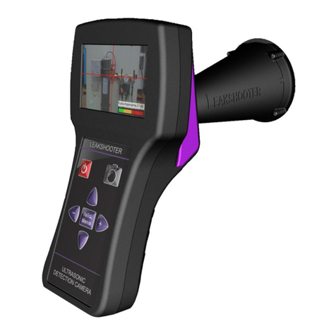
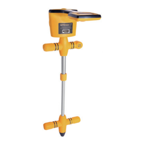
Vivax Metrotech vLocDM Instruction Manual

vLocDM User Handbook
(English Edition)
Version 2.1


Table of Content
1. General Safety & Care Information
1.1 Who Can Use this Equipment
1.2 Work-site Safety
1.3 Equipment Safety
1.4 Batteries and Environmental Safety
1.4.1 Alkaline Batteries
1.4.2 Rechargeable Batteries Nickel Metal Hydride and/or Lithium Ion
1.4.3 Lithium Metal Batteries (non rechargeable)
1.4.4 General Rules regarding Disposal of Batteries
1.4.5 Transportation of Lithium Ion and Lithium Metal Batteries
1.5 Care and Maintenance of Equipment
1.6 Care When Interpreting the Information Provided by the Locator
1.7 American & Canadian Safety Notices
1.7.1 USA
1.7.2 CANADA
1.7.3 EUROPE
2. Service & Support
2.1 Serial Number and Software Revision Number
2.2 Distributors and Service Centers Closest to You
3. Introduction
3.1 About this Handbook
3.2 Overview of the vLocDM System
3.3 Planning a Survey
4. Transmitter Functions and Operations
4.1 Transmitter Control Panel
4.2 Display
4.3 Power Supplies and Connections
4.4 Connecting to the Pipeline
4.4.1 Connecting at a CP (Cathodic Protection) Station
4.4.2 Connecting to the Pipe when there is No Access to a CP Station
4.4.2.1 SacricialAnode
4.4.2.2 Connecting at a Point where Access to the Pipe is Possible
4.5 Selecting the Correct Frequency
4.6 Output Current Select
1
1
1
1
1
1
2
2
2
2
3
3
3
3
3
3
4
4
5
6
6
6
7
8
8
8
8
9
9
10
10
10
11
11

4.7 Alarms
4.7.1 Over Voltage
4.7.2 Over Temperature
4.7.3 Over Power
5. Receiver Functions and Operations
5.1 LCD Features
5.2 Pushbutton
5.3 Connectors
5.4 Batteries
5.4.1 Charging Internal Batteries
5.5 Setting User Preferences
5.6 Setting Frequency Options
5.7 Setting Locate Mode
6. Using the vLocDM Receiver
6.1 Locating a Pipeline
6.2 Pinpointing
6.3 Taking Depth and Current Readings
6.4 Storing the Results
6.5 Graphing the Results
6.6 Using the A-frame Fault Finder
6.6.1 Fault Finding Method
6.6.2 Using the A-frame
6.6.3 Using the A-frame where there are Many Defects Such As Porous Coating
7. Using an External GPS Data Logger
7.1 Compatible GPS and GPS Data Loggers
7.2 Transferring Data to a PC
8. Interpreting Results
8.1 Introduction
8.2 Sources of Error
8.2.1 Operator Error
8.2.2 Interference (Distorted Fields)
8.2.2.1 Source of Interference (Distorted Fileds)
8.2.2.2 Checking for Distorted Fields
8.3 Downloading Data to a PC
8.4 Interpreting Graphs
9. Care and Maintenance
9.1 Cleaning
9.2 Checking Functionality
10. Data Sheet
11. Glossary
Notes
12
12
12
12
13
13
14
16
17
17
17
18
19
21
21
22
23
24
24
26
27
27
29
31
31
31
32
32
32
32
32
32
33
34
38
39
39
39
40
46

Page 1 of 47
General Safety & Care Information
1 General Safety & Care Information
1.1 Who Can Use This Equipment?
•Thisequipmentmustonlybeusedbypeoplesuitablytrainedintheuseofpipeandcablelocators.
1.2 Work-site Safety
• Useyourcompanies,orotherapplicablesafetycodesandruleswhenusingthisequipment.
•Unlesshavingtherequiredauthorization,licenseandappropriatetraining–DO NOT make connections to
anypipe,cableorconductor.
• DO NOTusesthisequipmentinexplosiveareas–suchasinthepresenceofflammableliquids,gases,heavydust.
• DO NOT directly connects this equipment to cables or pipes that have a potential difference to ground of
greater than 35V AC.
1.3 Equipment safety
• DO NOT open the enclosures (housings) of either the transmitter or receiver.
• Placethegroundstakefirmlyinthegroundbeforeconnectingthecablefromthetransmitter.
•DO NOT hold any uninsulated portion of the Connection leads & Clips when the transmitter is switched on.
1.4 Batteries and Environmental Safety
Vivax-Metrotech products use four types of batteries:
•Alkalinebatteries
•Ni-MH(NickelMetalHydride)–rechargeable
•Lithiumionbatteries–rechargeable
•Lithiummetalbatteries–(smallnonrechargeablebuttoncellsfor“clock”applications)
1.4.1 Alkaline Batteries
•Whenreplacingthealkalinebatteries–useonlythesizeandtypespecified–DO NOT mix battery types
(rechargeable and alkaline).
•DO NOTmixpartiallydischargedandfullychargedcellsinthesamebatterypack–DO NOT mix old with new.
•Neverattempttochargealkalinebatteries.
1.4.2 Rechargeable Batteries Nickel Metal Hydride and/or Lithium Ion
•Whenusingrechargeablebatteries,use only the correct charging device supplied or specified by the
manufacturer. The battery pack or the battery charger will contain circuitry to manage the charging process
–otherchargers(eveniftheyhavethesameconnector,polarity,voltage¤trating)willnothavethe
samecontrolcircuitryandcancausedamagetotheproduct,overheating,andinextremecasesreorharm
to the individual.
•DO NOTassumethatiftheplugtsitisthecorrectcharger–achargerwiththecorrectpartnumberMUST
beused–justbecauseitisaVivax-MetrotechchargerandtheplugtsDOES NOT mean it is the correct charger.

Page 2 of 47
• Beforeusingforthersttime,chargerechargeablebatteriesfor6hours.Ifatanytimetherechargeable
batteries DO NOTlastaslongasanticipated–dischargefullyandthenchargefor6hours.
• Careshouldbetakenwhenchargingbatteries–NEVER repeatedly recharge batteries (or turn power off
&on)withoutusingtheinstrument.Ifusedwithaninverterinavehicle–chargetheproductthenunplug
the charger and DO NOT charge again until the rechargeable batteries have been used for at least 10
minutes. Failure to do this could result in the overcharging of the battery which will shorten the life of the
battery,andcouldinsomecircumstancescauseoverheatingorre.
• IfevertheproductbecomeshotduringthechargingprocessIMMEDIATELY unplug the charger and use
the rechargeable batteries for at least 10 minutes before recharging. If this reoccurs the next time the unit
ischarged–returnimmediatelytoVivax-Metrotechforrepair.
• LithiumIon Batteries–someproductsuseLithium ionbatteries–therequirementsformarkingand
transportation are still developing. Please contact Vivax-Metrotech before shipping products containing
LithiumionbatteriesorLithiumionbatterypacksontheirownforany“specialinstructions”.
• DO NOT charge batteries for prolonged periods of time without using the locator for at least 10 minutes.
Chargingforprolongedperiodoftimecouldoverchargethebattery,reducethebatterylifeandinextreme
circumstancescausedamagetothelocatorandre.
1.4.3 Lithium Metal Batteries (non rechargeable)
• Commonlyknownas“buttoncells” thesearesmall–nonrechargeablebatteriesusedtopower internal
“clocks”withinsomeunits(similartocomputers).Generallytheyhavealifeof3-5years.
• Undernocircumstancesshouldanyattemptbemadetochargethesebatteries.
• Disposeofaccordingtoyourcompany’sworkpractice/environmentalstandards,theprevailing laws,or
recognizedbestpractice.Alwaysdisposeofbatteriesresponsibly.
1.4.4 General Rules regarding Disposal of Batteries
• NEVERdisassembleabattery,orbatterypack.
• Neverdisposeofinreorwater.
• Disposeof batteriesinaccordancewithyourCompany’sworkpractice/environmentalstandards,the
prevailinglaws,orrecognizedbestpractice.Alwaysdisposeofbatteriesresponsibly.
1.4.5 Transportation of Lithium Ion and Lithium Metal Batteries
• TheLithiumionandLithiummetalbatteriesusedinVivax-Metrotechproductsmeettherequiredsafety
standards and include the designated protection circuitry.
• Recentregulationchanges requirethatwhenbatterieswithLithiumionandLithiummetalbatteriesare
transported the packaging MUSTincludespeciedwarninglabels.
Please contact Vivax-Metrotech Customer Service (USA 1-800-446-3392 – international
+1-408-734-1400 (USA Pacic Time Zone) for more details.
• Regulationshavealsochangedregardingtheshippingofsparebatterypacks(batterypacksthatarenot
insideaproduct).Therearelimitationsontheweightofthepackage,andthepackagingmustbemarked
with the appropriate warning labels.
Please contact Vivax-Metrotech Customer Service (USA 1-800-446-3392 – international
+1-408-734-1400 (USA Pacic Time Zone) for more details.
1 General Safety & Care Information
WARNING
Remember – Batteries Contain Dangerous Chemicals
They can be affected by many things such as water ingress or heat. In some
circumstances, they can explode, they also can cause electric shocks!

Page 3 of 47
1.5 Care and Maintenance of Equipment
• UseequipmentonlyasdirectedinthisUserHandbook.
• DO NOT immerse any part of this equipment in water.
• Storeinadryplace.
• Keepequipmentinthecaseprovidedwhennotinuse.
• Ifleftforprolongedperiodoftime–removealkalinebatteries.
• Keepunitcleanandfreeofdustanddirt.
• Protectagainstexcessiveheat.
1.6 Care When Interpreting the Information Provided by the Locator
•Likealllocators–thisinstrumentislocating, andprovidingdepthandcurrentreadingsbasedon
electromagnetic signals that radiate from the buried cable or pipe. In most cases these signals will enable
the locator to pinpoint both position depth and current correctly.
•BEWARE–insomecasesotherfactorswilldistortelectromagneticeldsradiatingfromcableorpipebeing
located,resultinginincorrectinformation.
• Alwayslocateresponsibly,anduseinformationlearnedduringyourtrainingtointerprettheinformation
provided by the locator.
• DO NOT providesinformationregardingdepthofcableorpipetoanyoneunlessauthorizedtodosoby
your company.
• REMEMBERthatdepthmeasurementsaretothecenteroftheelectromagneticeldorpipe–Inthecase
ofpipesthismaybesignicantlydeeperthanthetopofthepipe.
1.7 American & Canadian Safety Notices
1.7.1 USA
•Thistransmitterandreceivercomplywiththegeneralconditionsofoperation,pursuanttopart15ofthe
FCC Rules.
•CFR47Part2:2004
•CFR47Part15:2006
•ANSIC63.4:2003
•Changesormodicationsnot expresslyapprovedbythemanufacturercouldvoidtheuser’sauthority to
operate the products.
1.7.2 CANADA
•Equipmentisforusebytrainedoperatorsonly,andnotforgeneralhouseholdorconsumeruse.
•Usagedurationshallbeasshortaspossible;topreventpossibleradiointerferencetoauthorizedservices,
especiallythe100kHzLoran-Cfrequency.
•Operationissubjecttothefollowingtwoconditions:(1)thisdevicemaynotcauseinterference,and(2)this
device must accept any interference that may cause undesired operation of the device.
1.7.3 EUROPE
•Vivax-Metrotechconfirmsthat thelocationsystemiscompliantwithrelevantprovision ofEuropean
directive 1999/5/EC.
•ETSIEN300330-2:2006
•ETSIEN301489-1:2005
•ETSIEN301489-3:2002
1 General Safety & Care Information

Page 4 of 47
2 Service & Support
2.1 Serial Number and Software Revision Number
Always quote your receiver and transmitter model and serial numbers and software revision number when
requesting product support. They can be found as follows: (for reference only)
Service & Support
1
1
1 Model # and Serial #
Note:
The transmitter Serial # and Model # can be
found at the bottom of the transmitter.
Onbothreceiverandtransmitter,thesoftware
revision is displayed on the LCD during the
start up sequence.

Page 5 of 47
2.2 Distributors and Service Centers Closest to You:
2 Service & Support
United State of America
Vivax-Metrotech Corporation
3251 Olcott Street,
Santa Clara, CA 95054, USA
Website : www.vivax-metrotech.com
Sales & Sales Support:
T/Free : +1-800-446-3392
Tel : +1-408-734-1400
Fax : +1-408-734-1415
Application Support:
T/Free : +1-800-624-6210
Tel : +1-408-454-7159
Fax : +1-408-743-5597
Service & Repairs:
T/Free : +1-800-638-7682
Tel : +1-408-962-9990
Fax : +1-408-734-1799
All Other Department:
T/Free : +1-877-330-1647
Tel : +1-408-734-3880
Fax : +1-408-962-9993
Canada
Vivax Canada Inc.
400 Esna Park Drive,
Unit 17, Markham,
Ontario, L3R 3K2, Canada
Tel : +1-289-846-3010
Website : www.vivax-metrotech.com
Europe
SebaKMT
Seba Dynatronic
Mess-und Ortungstechnik GmbH
Dr.-Herbert-Iann-Str. 6,
96148 Baunach, Germany
Tel : +49-9544-680
Fax : +49-9544-2273
Website : www.sebakmt.com
Australasia
SebaKMT AUS
Unit 1, 176 South Creek Road,
Cromer NSW 2009, Australia
Tel : +61-2-9972-9244
Fax : +61-2-9972-9433
Website : www.sebakmtaus.com
China
Leidi Utility Supply (Shanghai) Ltd.
Rm405 3rd Building No. 641, Tianshan Rd,
Shanghai, China 200336
Tel : +86-21-5187-3880
Fax : +86-21-5168-5880
Website : www.leidi.com

Page 6 of 47
3 Introduction
Introduction
3.1 About this Handbook
This handbook is designed to provide the user with a comprehensive understanding of the operation of the
vLocDMsystem.ThehandbookassumessomeunderstandingofCathodicProtectiontechniques,itcoversthe
operationoftheequipment,thetechniquestogatherdata,storingandretrievingthedatainaformatthatcanbe
analyzedbyacompetentengineerandabriefexplanationofhowtousethedatatoformanunderstandingof
the condition of the pipe network.
3.2 Overview of vLocDM System
The vLocDM (Defect Mapper) has been designed to:
•identifythepositionofcoatingdefects
•identifyshortstootherstructures
•helpcategorizethefaults
•helpplanandprioritizeremedialwork
The vLocDM uses the latest locating and signal processing techniques to plot the current gradient of an industry
standardlowfrequency(3Hz)prolingcurrent.ThecurrentistypicallyappliedatCPstationssothedisruptionof
thepipelinecanbeminimized.
TheLoc-150Tx,150Wtransmitter(vLocDMtransmitter)isusedtoapplyasignalcurrenttotheanodebed.The
pipeline returns the signal via coating faults back to the transmitter. The transmitter is designed to be powered
fromCP(CathodicProtection)stations,ACorexternalbatteries,eliminatingtheneedforbatteries.
Thenon-intrusivemeasuringdevice, thevLocDMreceiver,takesmeasurements alongthepipelineandplots
the results directly onto the screen of the receiver. There is no need to carry extra logging and display devices.
All the data is displayed and logged into the receiver and can be downloaded to a spread sheet or dedicated
analysis program such as Spectrum XLITM or similar.
A +/- 3m accuracy GPS antenna is included with the system. It links to the vLocDM receiver via Bluetooth radio
link. The GPS enables the user to generate real time current gradient graphs and guides the user back to a point
ofinterestbyhighlightingtheuser’spositiononthegraph.Thisfeatureiscalledthe “walkback”feature.The
systemcanalsobeintegrated withhighaccuracyGPSsystemsandsoftwarepackages, forexampleTrimble
and TriGlobal Inc.
Storing the results also has the benefit of facilitating the technique of comparative tests. Comparing the
results from previous surveys of the same length of pipe allows the CP engineer to establish trends of coating
deterioration.
TheA-framefaultndingaccessoryisusedtoaccuratelylocatethepositionofafault.Anarrowpointstheuser
tothepositionofthefaultwhilstquicklyandefcientlygraphingthecharacteristicshapeandmagnitudeoffault
signalonthereceiver'sdisplay.Thisensurestheuserminimizesthechancesofmisidentication.

Page 7 of 47
3.3 Planning a Survey
Surveyswillvarygreatlydependingontype ofterrain,accessibility,conditionofpipeline,typeofpipelineand
coating type.
The first step of undertaking any survey should be to obtain information about the stretch of pipeline to
be surveyed. More work at this stage may well save time and effort later. Obtaining maps showing route
information,CPstations,sacricialanodesandcrossbondingpointswillbeofgreathelp.
Thetransmittershouldbecapableof transmitting fromoneCPstationtoanother,soalthoughnotabsolutely
necessary,plantohavethepreviousandafter CPstationsdisconnectedfromthestretchofpipelinetobe
surveyed.Rememberthatthe pipelineisnotprotectedwhilstthesurveyisbeingundertaken,sounnecessary
downtime of CP stations should be avoided.
Choosethesurveyintervaltomatchtheconditionofthepipeline.Inareaswherethecoatingisparticularlypoor,
asurveyintervalofaslittleas10mmaybedesirable.However,ifthecoatingisinverygoodconditionandthe
distancebetweenCPstationsismanykm, itmaybebettertochooseasurveyintervalofasmuchas 200m.
Taking measurements at large intervals will enable the surveyor to quickly asses the condition of the pipeline
and subsequently identify areas that require further inspection at closer survey intervals or detailed analysis
using the A-frame Fault Finder accessory.
WARNING
Parts of the pipeline may be crossing road junctions and may even follow the route of
roads. Obtaining accurate results from the vLocDM requires full concentration from
the operator. It is therefore essential that correct trafc management is undertaken at
these points to avoid poor results or injury to the operator. Safety should always be
the rst concern.
3 Introduction

Page 8 of 47
4 Transmitter Functions and Operations
Transmitter Functions and Operations
4.1 Transmitter Control Panel
4.2 Display
0.60 A
98Hz
600 mA
VOLTAGE LIMIT!!!
POWER LIMIT!!!
4.3 Power Supplies and Connections
1
2
3
4
5
1 Mains Input
2 Mains Input Fuse
3 12-60V DC Input
4 Output Fuse
5 Output Socket

Page 9 of 47
4.4 Connecting to the Pipeline
4.4.1 Connecting at a CP (Cathodic Protection) Statio
WARNING
Connecting to the CP station involves removing connections from the CP transformer
rectifier and should only be performed by authorised personnel. Always make
connections before switching on the unit. Switch off before disconnecting the transmitter.
Method:
1. Make a note of the CP settings (Output Current and Voltage settings). This is important as the settings
must be checked to ensure they return to the original settings when the connections are re-made.
2. Switch off the CP transformer rectifier and allow the residual voltage to dissipate. This may be a few
seconds or a few minutes depending on pipe condition.
CP
Station
-Ve +Ve
Mains Socket
DC Output
To Anode Bed
Standard CP
Station Connections
3. Disconnect the output wires connecting the CP station to the pipeline and anode bed. If there is an earthed
mainssocketatthestation,connectthetransmittermainspowerleadtothesocket.
4 Transmitter Functions and Operations

Page 10 of 47
4. Ifthereisnomainssocket,itispossibletousetheDCoutputofthetransformerrectier.Seediagrambelow.
5. Adjustthetransformeroutputtoapproximately40VDC(althoughtheunitwillfunctionfrom12VDCto60V
DC) and use the DC input lead to connect the transmitter to the transformer terminals.
6. With the output leadconnectedtothetransmitter, connecttheRedwire tothelead connecting tothe
pipeline. Connect the Black wire to the lead connecting to the anode bed. See diagram above.
4 Transmitter Functions and Operations
4.4.2 Connecting to the Pipe when there is No Access to a CP Station
4.4.2.1 Sacricial Anode
Veryoftenthecableconnectingasacricialanodetoapipeisfedthroughanabovegroundconnectionbox.If
this is the case the anode can be disconnected and these cables used to connect the transmitter to the pipe.
TheRedconnectionleadneedstobeconnectedtothepipesideandtheBlacktothesacricialanode.
Itwillbenecessarytopowerthetransmittereitherfromaportable110VACmainsgenerator,orfromavehicle
car battery or external 12V DC power source.
4.4.2.2 Connecting at a Point where Access to the Pipe is Possible
It is possible to connect the transmitter at any point along the pipe length where an electrical connection is
possible. If this is the case a good independent ground will need to be generated by driving a ground stake
into the ground a few meters perpendicular to the pipe. The ground needs to be low impedance so the copper
ground rod needs to be at least 0.5 meters long. In some cases multiple stakes may be necessary.
A poor ground will result in the transmitter showing the over voltage alarm even at low currents. If this occurs
add further ground rods connected in parallel and dampen the surrounding soil.
NOTE
It may not be possible to attain high current from the transmitter, as a sacricial anode will
not provide as good a ground as a system anode bed.
NOTE
If the output leads are white and green, the white cable should be connected to the pipe.

Page 11 of 47
4.5 Selecting the Correct Frequency
The available frequency options are:
•98Hz,128Hz,512Hz,640Hz,3Hz/98Hz,3Hz/128Hz,4Hz/98Hz
•4Hz/128Hz
•ELF1-3Hz/6Hz/98Hz
•ELF2-3Hz/6Hz/128Hz
•ELF3-4Hz/8Hz/98Hz
•ELF4-4Hz/8Hz/128Hz
•3Hz/6Hz/512Hz
•3Hz/6Hz/640Hz
•4Hz/8Hz/512Hz
•4Hz/8Hz/640Hz
3Hz/6Hz/98Hzor3Hz/6Hz/128Hzarethemost commonly usedfrequencies.Theyprovidethelow frequency
3Hzcomponentrequiredforcurrentmappingand alowfrequency(98Hzor128Hzdependingonlocal mains
frequencies)usedtopinpointthepositionandisusedtodeterminethepipedepth.The6Hzenablesthelocator
to calculate the signal direction.
The other frequency options can be used to improve reception in areas of high interference.
4.6 Output Current Select
There are seven current settings:
•100mA
•300mA
•600mA
•1A
•2A
•3A
•4A (When a single locate frequency is selected)
Choosingthecorrectsettingfor aparticularapplicationdependsonmanyfactorsbut asageneralrule“the
higherthesettingthebetter”.Thehigher thecurrentthemorestablethereadingsatlongdistanceandlarger
currentscreatelargercurrentchangesatfaults.However,itwillnotalwaysbepossibleordesirabletoapplythe
maximum current.
Withthetransmitterconnected asabove,selectthe3Aposition.Waittosee ifanyalarmsaredisplayedsuch
asovervoltage,overpower,overtemperature.Ifafter20secondsnoalarmsareshown,notethereturncurrent
reading. This should be 3A+/- 0.1A. Now note the output voltage. This should be less than 100V. The transmitter
stabilises the output current by altering the output voltage. The output voltage limit is 100V. If the current cannot
be stabilised with a voltage less than 100V it will display an overvoltage alarm. The transmitter is not damaged if
thisisdisplayedbuttheoutputwillnotbestabilised.Toovercomethis,selectalowercurrentsetting.
4 Transmitter Functions and Operations
WARNING
Use a cable locator to ensure the area is clear of services before the rod is driven into
the ground.

Page 12 of 47
Other causes of overvoltage alarms are:
•Pipelineinverygoodcondition(Smallhighimpedancefaultswillrequirehighervoltagestoachievethe
requested current)
•Pooranodebed(Pooranodebedswillrequireahighvoltagedropacrossthemtocreatetherequestedcurrent)
•Poorpipeconnections
4.7 Alarms
4.7.1 Over Voltage
Output exceeds 100V. (Also see Output Current Select)
4.7.2 Over Temperature
Theovertemperaturealarmwillshowsonthedisplaywhenthetemperatureoftheoutputamplierexceedsa
predetermined level. At this temperature the unit will shut down and cannot be switched on until the unit has
cooled down.
Aftertheunithasbeencooleddown,itmaybenecessarytoplacetheunitinapositionwheretheambient
temperature is less such as shaded position. Alternatively select a lower current output.
4.7.3 Over Power
The Over Power alarm will be shown on the display when the output power rating of the transmitter is reached.
The unit will shut down until the output power is reduced.
This can be doing either:
•Reduce the output current setting
•Improve the ground and pipe connections (This may be the case where the ground used is not an anode
bed. For instance where a ground rod is used because access to a CP station is not possible.)
4 Transmitter Functions and Operations

Page 13 of 47
Receiver Functions and Operations
5Receiver Functions and Operations
5.1 LCD Features
1 Locate Mode
2 Speaker Status
3GPSOptionActive,barsindicateaccuracy
4 Bluetooth Active
5 External Battery Indicator
6 Internal Battery Indicator
7 Last Record Number
8 Distance From Last Measurement
9 Left/Right Indicator
10 Locate Frequency
11 Signal Strength
12 Pipe Direction Indicator
13 Gain Setting
14 Depth to Centre of Pipe

Page 14 of 47
5Receiver Functions and Operations
5.2 Pushbutton
Graphing Screen Graph Review
Locate Screen Measure Screen
On/Off On/Off
Change frequency Not active
Short press for measure and
long press for user menu Jump back to Locate Screen
Increase gain Save and go to graph
Decrease gain Rejectandgotographandlong
press to delete log in memory
Change antenna mode Save a record and return
to Locate Screen
Pushbutton
Pushbutton
On/Off On/Off
Not active Not active
Highlights active graphing button Deletes highlighted log
Zoom in (scroll right/up) and long press
toautoscalehorizontalaxis
Return to Locate Screen Returns to Graphing Screen
Moves curser right.and also used to
conrmdelete
Zoom out (scroll left/down) and long
press to auto scale vertical axis Moves curser left
Log 2
13.2mA 19.7m To Delete
Press
Table of contents
Other Vivax Metrotech Security Sensor manuals
Vivax Metrotech
Vivax Metrotech VM-810 Instruction Manual
Vivax Metrotech
Vivax Metrotech vLoc3-9800 Instruction Manual
Vivax Metrotech
Vivax Metrotech VM-480B Instruction Manual
Vivax Metrotech
Vivax Metrotech vLoc3-DM Instruction Manual
Vivax Metrotech
Vivax Metrotech vLoc3 RTK-Pro Instruction Manual
Vivax Metrotech
Vivax Metrotech VM-500 Series Instruction Manual
Vivax Metrotech
Vivax Metrotech vLoc3 Series User manual
Vivax Metrotech
Vivax Metrotech VM-550 User manual

Vivax Metrotech
Vivax Metrotech vLoc3 RTK-Pro Instruction Manual
