Vivint ML01 User manual

Installation Instructions —
Installing the
Vivint Spotlight Pro is a multi-step procedure but it is straightforward and can be quickly learned and mastered. The Smart Home Pro should carefully read all of the
se
steps (and
tips below) in order to ensure a successful installation and optimal performance. The steps below describe a new installation of the Spotlight Pro with the Outdoor
Camera Pro (Gen 2)
. For additional information, including details about the Wi-Fi bridge as well as replacing an existing camera, refer to the Field Service Smart Home Pros website.
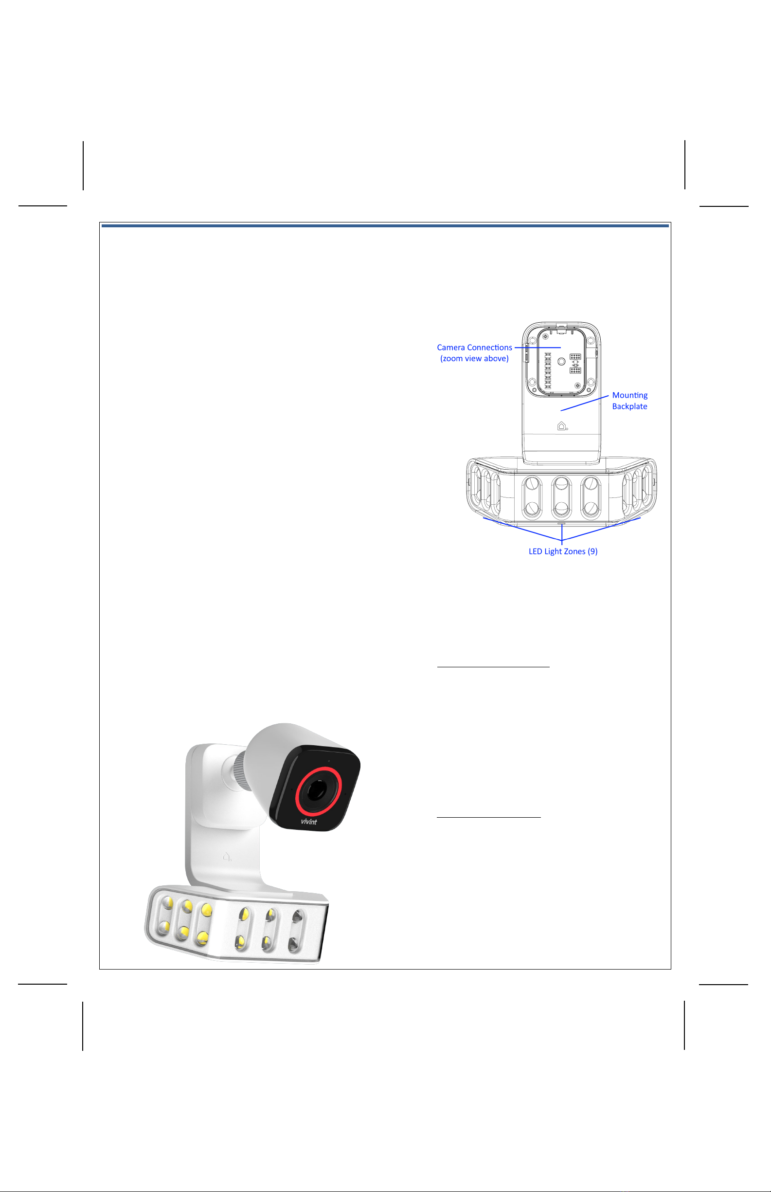
Outdoor Camera Base (inside) —
Figure-2: Wire Terminal Colors —
4931 N 300 W Provo, UT 84604
The Vivint
Spotlight Pro is a state-of-the-art outdoor lighting fixture that is used with the Vivint Outdoor Camera
Pro
(Gen 2). The combined spotlight and outdoor camera can be added to a Vivint Smart Home system in order to
provide
enhanced home and perimeter security. The Spotlight Pro replaces the standard backplate for attaching
the outdoor camera
, while adding customizable 9-zone LED spotlight functionality. With the spotlight camera, the
homeowner can schedule times to either deter threats (people, cars, animals
, etc.) or provide everyday outdoor
lighting.
(NOTE: The Spotlight Pro is suitable for installation in damp locations.)
K
ey features of the Spotlight Pro include: Deter Mode with spotlight tracking and escalated lighting behavior such
as strobe,
wave, full brightness, plus a deterrence tone from the camera speaker; Non-Deter Mode (i.e., everyday
outdoor
lighting) with full ambient flood lighting for when a person is detected. The user can control these
behaviors
, create schedules and custom rules, and adjust various settings at any time via the app or at the panel.
T
he spotlight and camera uses a reliable hard-wired connection (for fast smooth video) to the Vivint system and
the
home's router with a Wi-Fi bridge, that supplies both power and network connectivity.
IMPORTANT
:The Spotlight Pro (M/N: ML01) may only be installed with the Outdoor
Camera
Pro (Gen2) (M/N: CM05). It is suitable for operation in ambient not exceeding 40°C.
This
document includes a product description, installation instructions (new install only), basic operation / user
functionality
overview, as well as technical specifications and regulatory compliance notices and declarations.
Vivint
Spotlight Pro
(V
S-ODL100-WHT)
Quick Reference (User Manual — Installation & Operation)
PRINT INSTRUCTIONS:
REFERENCE SHEET FOR VS-ODL100-WHT P/N 77-600054-001 REV 1.0 |
INK: BLACK | MATERIAL: 20 LB MEAD BOND | SIZE: 8.50" X 11.00" SCALE 1:1 |
FOLDS: BI-FOLD VERTICAL, BI-FOLD HORIZONTAL (TO FIT IN BOX)
To install the wiring, spotlight fixture, and outdoor camera, follow these steps:
1. Identify the best location to install the spotlight and camera, consulting with the homeowner (see
"Installation Tips"). Also, locate the indoor outlet where you will run the wire and plug in the Wi-Fi bridge.
IMPORTANT: The camera MUST be installed on a vertical wall at least 10' above the ground.
2. Run Ethernet Cat5e wire from the spotlight camera to the outlet, leaving excess wire at both ends.
IMPORTANT: The Cat5e wire must be "UL Listed" cable.
3. At the outlet location (where the Wi-Fi bridge will be plugged in), to terminate the Cat5e wire:
a) Drill a hole near the outlet, and pull the wire down through the wall. IMPORTANT:
Make sure to drill and
pull wire outside of the outlet box, even if it's close enough to be covered by the outlet cover plate.
b) Terminate the wire with an RJ45 jack according to the T-568B order. Strip 1" of the jacket to expose the
4 wire pairs, use the pull string to remove 2" more and cut off the jacket and string, trim the corners,
untwist the pairs, line up the wires in the T-568B order (see Figure-1 below), straighten the wires and
remove any gaps, cut the wires to ¾" with a straight cut, and slide the RJ45 jack down over the 8 wires.
c) IMPORTANT: Make sure the orientation is correct; push the wires completely under the pins; the jacket
must be pushed under the strain-relief; securely crimp the RJ45 with the 8-pin tool.
4. At the spotlight and camera mounting location, to terminate that end of the Cat5e wire:
a) Use the spotlight backplate to mark the location of the wiring hole, drill the hole in the home's exterior
surface, and then run the Cat5e wire through both the wall and the rubber seal on the backplate.
b) Terminate the wire on the inside of the backplate. Strip 1.25-1.5" of the jacket to expose the 4 wire
pairs, untwist each pair and arrange them over the terminal that corresponds with their color (see
Figure-2 below), use the custom punch-down tool to connect each wire to its matching terminal.
c) IMPORTANT: Do not strip wires; do not punch at an angle; inspect each terminal to ensure the wire is
completely inserted; trim off excess wire; make sure the rubber seal is tight for waterproofing.
5. Mount the spotlight and camera, first attaching the spotlight backplate to the exterior surface with four
screws (use either #6 1" stainless steel self-drilling screws, or #6 1.25" galvanized deck screws) and anchors.
(NOTE: You should use a spacer if you're unable to place the backplate directly over the wiring hole.)
6. Next attach the camera to the backplate, using the T5 screw (9 mm) as a hinge rotating the camera until it
firmly snaps into place. The pins will establish an electrical connection, supplying power once the Wi-Fi
bridge is connected. IMPORTANT: Make sure the wires are not powered on before attaching the camera.
7. Adjust the camera to the desired angle/FOV (using the ball cap slot), and hand-tighten the ball-joint ring.
8.
Add the camera to the system
, go to "Adding the Spotlight and Camera to the System" to complete setup.
INSTALLATION TIPS / BEST PRACTICES
•Adhere to the height restrictions — 10' min. to 11' max.
•Ensure the wire is undamaged and hidden from view.
•Avoid metal outlet covers that can pinch wires inside
the cable and cause failures over time.
•If you are mounting on an uneven surface (brick, etc.),
make sure the backplate does not get twisted as this
can potentially impact the pogo pin/pad connections.
•Use the optional spacer piece if an external wire run is
necessary (e.g., from an eave/soffit to the camera).
•Use the optional wedge piece if installing higher than is
typical and it's needed to gain the desired angle/FOV.
•To detach the camera, remove the T5 screw, insert a
narrow pointed tool into the release latch opening, and
separate the camera from the backplate.
Spotlight Pro Backplate (top zoom in) —
Figure-1: RJ45 Wires in T-568B Order —

Troubleshooting Tips
If the
spotlight camera is offline, attempt these troubleshooting steps in order to resolve:
Power cycle or reboot the Wi-Fi bridge
Factory reset the Wi-Fi bridge
Power cycle the spotlight camera
Factory reset the spotlight camera (press the button for 5 seconds)
Ensure wire termination points are clean and secure
Ensure wire terminations are following the T-568B order (see Figure 1 and Figure 2)
Ensure punchdown terminations are fully seated
Spotlight Pro with Outdoor Camera Pro (assembled) —
Spotlight Pro (front view) —
Operation Overview / User Functionality
Once the
spotlight camera is up and running, the customer can use the
Vivint
app for onboarding and initial configuration, as well as perform
the following functions
via the app (and the panel for certain features).
For detailed
step-by-step instructions, refer the customer to the online
Help resources (articles and video tutorials) at the Vivint Support site.
SPOTLIGHT SPECIFIC FEATURES
•Enable, configure, and schedule Deter Mode (detects and
tracks intruders using the camera's analytics software; uses
escalated light behaviors such as strobe, wave, full brightness)
•Configure each of the 9 LED light zones independently
•Enable, configure, and schedule Non-Deter Mode (everyday
outdoor ambient lighting behavior when a person is detected)
•Turn the light on and off, dim the light (0% - 100%), manually
trigger escalated Deter Mode at any time during nighttime
hours, integrate light behaviors with custom rules and system
events (door open/close, doorbell ring, etc.)
•Enable neighbor friendly lighting (permanently disable any LED
light zones that may annoy the neighbors)
Additionally, at the panel Devices > Cameras settings page, the user
can
also perform these management and configuration tasks:
•Adjust person detection and video settings
•Rename the spotlight camera
•Reboot and/or delete the spotlight camera device
Adding the Spotlight and Camera to the System —
Now that the Ethernet wiring is
prepared (to supply both power and network connectivity through the Wi-Fi bridge), and the spotlight and camera are installed,
the next steps are
to
power up the spotlight camera and add it to the Vivint system via the Installer Toolbox, at the control panel, by using the method below.
To add the spotlight and camera to the system, follow these steps:
1. If the Vivint control panel is not already up and running, apply 100-240 VAC power to the
panel and wait for it to boot up completely.
2. Verify the panel is connected to the local network. To do this, at the panel tap on the menu
icon (…) on the touchscreen > tap Software version > enter the PIN code 2203 to access the
Installer Toolbox > tap Networking > Panel connection to the local network > Wired > and
then tap Back to return to the Networking page and verify the status is "Connected".
3. Now you can apply power to the spotlight camera by first plugging the Wi-Fi bridge into the
outlet, and then plugging the Ethernet RJ45 jack coming from the camera into the Wi-Fi
bridge. (NOTE: The Wi-Fi bridge adapter must be "UL Listed".)
4. Add the spotlight camera to the system. To do this, at the panel access the Installer Toolbox >
tap Smart Home devices > Cameras > and then tap Add camera. (NOTE: This procedure
describes how to add the camera via the Wi-Fi bridge using the WPS Pro option; the panel
also provides two other methods: Wi-Fi Connect and NFC. Refer to the FSP site for details.)
5. Tap WPS Pro > and then tap Add. When the panel shows "Listening for device" go to the Wi-
Fi bridge and press and hold the WPS button for 3-5 seconds. The Internet LED will begin
blinking red.
6. The panel will show that the device is "Found" and being its configuration. You can tap
Camera details to monitor configuration progress. Wait until the camera status shows
"Online" before finishing the camera setup. IMPORTANT: This process should NOT be
interrupted and could take several minutes to load firmware and configure settings.
7. Once the spotlight camera is successfully connected and online, you can enter a descriptive
name to uniquely identify the device.
8. At the panel Home screen, tap the camera icon in the navigation bar at the bottom of the
touchscreen, and then tap the thumbnail view for the camera you just added to verify that
you can view live video at the panel screen.
9. The customer can now use their Vivint app (and the panel for certain features) to view live
video, and to access, control, and configure settings for the spotlight camera. See "Operation
Overview" for an introduction to specific features and direction to additional Help resources.
CAMERA SPECIFIC FEATURES
•View a live video feed
•View recorded video clips (enable recording options)
•Enable 24/7 DVR recording
•Receive person-triggered (event) notifications
•Enable Smart Deter detection (with the LED light ring and
selected chime tone)
•Engage in two-way talk with someone at the camera
•
Enable privacy mode

Technical / Hardware Specifications
Vivint Part Number (P/N)
VS-ODL100-WHT
Model Number (M/N)
ML01
Color
White
Weight
600 g
Dimensions
174.7 x 164.1 x 76 mm (6.9 x 6.5 x 3 inches)
LEDs
9 LED light zones with 2 LEDs/Zone (White, CCT:5000K, CRI:>80; +7 year life)
Light FOV
180° illumination coverage field of view
Connectivity
4PPoE (Power over Ethernet) network connection (2.4/5.0GHz via the Wi-Fi bridge)
Power Input
4PPoE (Power over Ethernet) power supply (specification: 802.3bt,Type 3, Class 5)
Power Usage
25W max. (spotlight will be the negotiator of power with the camera via PD controller
capable of 40W; camera requires 15W)
Backup Battery
None
Environmental Temperature
-4°F to 104°F (-20°C to 40°C)
IP Rating / Weatherproofing
IP65 / UV Protection
Regulatory Certifications
FCC: Part 15, Subpart B, Class B (USA)
ISED Canada: ICES-003, Class B (Canada)
UL Listed (USA & Canada)
FCC and ISED Canada Regulatory Compliance Declarations*
CAUTION!
Unauthorized changes or modifications could void the user’s authority to operate the equipment.
This device has been tested and found to comply with the limits for a Class B digital device, pursuant to
Part 15 of FCC Rules and Industry Canada license-exempt RSS
standard(s). Operation is subject to the following two conditions:
(1) This device may not cause harmful interference, and
(2) This device must accept any interference received, including interference that may cause undesired operation of the device.
These limits are designed to provide reasonable protection against harmful interference in a residential installation. This e
quipment generates, uses, and can radiate radio
frequency
energy and, if not installed and used in accordance with the instructions, may cause harmful interference to radio communications. However, there is no guarantee
that interference will not occur in a particular installation. If this equipment does cause h
armful interference to radio or television reception, which can be determined by
turning the equipment off and on, the user is encouraged to try to correct the interference by one or more of the following m
easures:
•Reorient or relocate the receiving antenna.
•Increase the separation between the equipment and the receiver.
•Connect the equipment into an outlet on a circuit different from that to which the receiver is connected.
•Consult the dealer or an experienced radio/television technician for help.
PR
UDENCE! Changements ou modifications pourraient annuler le droit de l'utilisateur à utiliser l'équipement non autorisées.
Conformément à la réglementation d'Industrie Canada, le présent émetteur radio peut fonctionner avec une antenne d'un type et
d'un gain maximal (ou inférieur) approuvé
pour l'émetteur par Industrie Canada. Dans le but de réduire les risques de brouillage radioélectrique à l'intention des autr
es utilisateurs, il faut choisir le type d'antenne et son
gain de sorte que la puissance isotrope
rayonnée équivalente (p.i.r.e.) ne dépasse pas l'intensité nécessaire à l'établissement d'une communication satisfaisante.
Le présent appareil est conforme aux CNR d’Industrie Canada applicables aux appareils radio exempts de licence. L’exploitatio
n est autorisée aux deux conditions suivantes:
(1) l’appareil ne doit pas produire de brouillage, et
(2) l’utilisateur de l’appareil doit accepter tout brouillage radioélectrique subi, même si le brouillage est susceptible d’en compromettre le fonctionnement.
Ces limites sont conçues pour fournir une protection raisonnable contre les interférences nuisibles dans une installation rés
identielle. Cet équipement génère, utilise et peut
émettre une énergie de radiofréquence et, s'il n'est pas instal
lé et utilisé conformément aux instructions, il peut causer des interférences nuisibles aux communications radio.
Cependant, il n'existe aucune garantie que des interférences no se produiront pas dans une installation particulière. Si cet
équipement provoque des interférences nuisibles à la
réception radio ou télévision, ce qui peut être déterminé en mettant l'équipement hors et sous tension, l'utilisateur est encouragé à essayer de corriger l'interférence par une ou
plusieurs des mesures suivantes:
•Réorienter ou déplacer l'antenne de réception.
•Augmentez la distance entre l'équipement et le récepteur.
•Connecter l'équipement à une sortie sur un circuit différent de celui sur lequel le récepteur est branché.
•Consulter le revendeur ou un technicien radio / télévision expérimenté pour de l'aide.
*For
complete regulatory compliance information, go to: vivint.com/legal/fcc
© 2022 Vivint Inc. All Rights Reserved.| www.vivint.com | 1-800-216-5232 | Device M/N: ML01 | Doc P/N: 77-600054-001 Rev. 1.0
Warning: California Proposition 65
This product can expose you to chemicals including lead, which is known to the State of California to cause cancer
and birth defects or other reproductive harm.
For more information, go to
: https://www.P65Warnings.ca.gov
This manual suits for next models
1
Popular Spotlight manuals by other brands

brennenstuhl
brennenstuhl EL 2000 MA operating instructions

Larson Electronics
Larson Electronics GL-4600-XD Instruction guide

Future light
Future light MH - 860 Service manual

Niethammer
Niethammer LPZ 211 D instruction manual

Strong International
Strong International FOLLOW SPOTLIGHT 48057 instruction manual

Black & Decker
Black & Decker 2 MILLION Power Series user manual

brennenstuhl
brennenstuhl 1171260111 manual

Eurotops
Eurotops 46593 instruction manual

Stanley
Stanley HIDLISL instruction manual

Altman
Altman PHX Series user manual

Larson Electronics
Larson Electronics Golight RadioRay GL-7 GT Series instruction manual

technocraft professional
technocraft professional PEN LIGHT manual