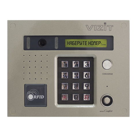
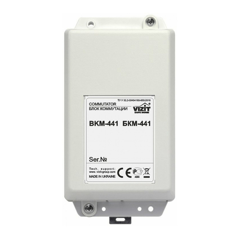
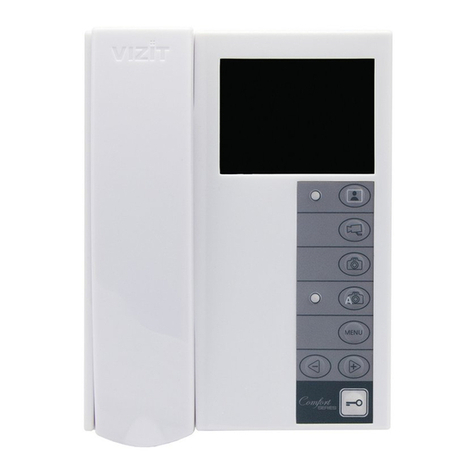
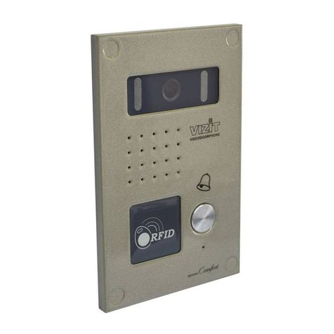
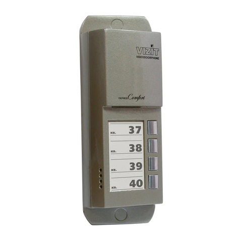
ViziT BK-4MVE User manual

BK MVE
BPD
FEATURES
PARTS LIST
BK MVE
SAFETY INSTRUCTIONS
V
INSTALLATION
-4
OPERATING INSTRUCTION
VIZIT
24/12-1-1
-4 1
13
1
30
is intended for operation in video doorphones as
commutation device between the doorstation and subscriber handsets
--4
-
-
-
.
with a
/ control unit devices (monitors and apartment UKP).
The device is also applied to connect monitors to the video line and a group power supply unit. The unit is
recommended for the purpose.
Simple apartment number coding similar to BK MV
Enhanced noise resistance for video signal distribution
Supply voltage to monitors from a power supply unit (BPD) with short-circuit protection and overload protection
Automatic recovery after short-circuit or overload
Commutator pc.
Jumpers pcs.
Operating instruction pc.
The device does not contain voltage above
Do not make any connections or repair when the power is on.
Commutator the device hereinafter
In case your video doorphone includes monitors with mains-operated switching adaptors (either built-in, or external),
shall be carried out as described in the sections and
. Protective earthing connection is required to remove voltage from terminals of the device, which
appears due to leakage current flowing from the mains-operated switching adaptors that supply monitors connected to the
device.
Before getting started, make sure that all monitors are disconnected from the mains V
()
.
~ 220 .
BK MVE
Caution
protective earthing connection CONNECTIONS EXAMPLES OF
WIRING DIAGRAMS
For qualified installation, wiring and servicing refer to technical and commercial partners of VIZIT TM. The list of
companies is given on VIZIT.EU ( .
-4
http://vizit.eu/eurounion/)
- Drill two holes in a wall, with
diameter mm and depth mm
- Drive anchors (2) into the holes
(1)
630.
6х30 .
-
.
Fix the device by fastening 2 screws 25
in the anchors
3.5х (3)
(1) - DIN- 35 1-2
(2) - -
rail, width mm, depth mm
Holder for fixing on a DIN rail
1
2
1
2
3
Figure1 - Mounting on a wall
Figure 2 - Mounting on a DIN-rail
Note. Fasteners are not supplied.
www.vizit-group.com BK-4MVE Operating Instruction (revision 6 12 8201 - ) 1/

CONNECTIONS
match wave impedance
last BK-4MVE in the video circuit
all the rest BK-4MVE Z shall be removed
1, 2, 3, 4 5, 7, 10, 14
first no jumpers FB, FC FD 1
successive
umper connects an Ohms resistor to of the coaxial cable. The jumper shall be set
up only in the top device in the diagram, i.e. in the .
In devices jumper
Apartment numbers may be of the same decade or of different
decades.
The examples of wiring diagrams (Fig. 6, 7) show how to connect monitors and apartment handsets UKP from
apartments No to the first commutator, and apartments No to the last commutator.
Note that in the pictures the commutator has in and zones, because in case of adding “ "
(when the apartment numbers are ) no jumper is required.
82
.
.
Z
·
·
·
Take off the device cover to access the PCB.
Video doorphone cables are connected to the terminals on the PCB.
Apartment number coding is carried out by setting jumpers on the PCB.
J
Program apartment numbers by setting the jumpers.
The number of apartment connected to the terminals in zone is set by jumpers, and shall be equal to the
above the jumpers.
The number of apartment connected to the terminals in zone is equal to number from to set by
2 jumpers in zone according to the table on the PCB.
The number of apartment connected to the terminals in zone is equal to number from to set by
2 jumpers in zone according to the table.
The number of apartment connected to the terminals in zone is equal to number from to set by
2 jumpers in zone according to the table.
:(),
:(),
:(),
FA 1 to 8 sum of
numbers
FB figure
FB
FC B figure
FC
FD C figure
FD
FA + 1 4
F+ 1 4
F+ 1 4
Jumpers set in FA, FB, FC, FD zones
are intended for apartment number programming.
Jumper Z connects
a mating resistor 82
to the video line.
W
Terminals layout and destinations, jumpers purposeFigure 3 -
-
-
+EA/+EB/+EC/+ED Supply voltage to monitor
VOA/VOB/VOC/VOD
VGA/VGB/VGC/VGD
GA/GB/GC/GD
FA/FB/FC/FD - Intercom line “minus”
LN - Intercom line plus
-
-
“”
Video out
Video ground
Ground
+EA
VGA
GA
VOA
FB FA+= FC FB+= FD FC+=
FA 80= +40+20+10+8+4+2+1
VO
Z
VG
VG
VI
+E
+E
G
G
LINE
GND
Ek
SEL
+1
+2
+3
+4
Commutator
-BK 4MVE
To monitor 1
To monitor 2 To monitor 3 To monitor 4
Intercom line
from the control unit()
Power line
from a group
power supply unit
Video line
coaxial cable)(
FA
LN
+EB
VGB
GB
VOB
FB
LN
+EC
VGC
GC
VOC
FC
LN
+ED
VGD
GD
VOD
FD
LN
Protective conductor
www.vizit-group.com BK-4MVE Operating Instruction (revision 6 12 2 8201 - ) /

·
·
·
().
1.
2.
3.
).
4 -
Connect cables following the examples of wiring diagrams refer to the section
For connections,
In case the device connects a monitor / monitors powered from switching adaptors,
shall be carried out as described below:
Lay a trunk protective conductor with yellow-green insulation and copper wire cross-section of 1.5 mm from the main
protective conductor of the building to the last BK-4MVE device in the video circuit, which has connected monitors
powered from switching adaptors.
Connect the trunk protective conductor to the main protective conductor of the building.
protective connected monitors powered from switching
adaptors to the trunk protective conductor (see the sections and
Connection of the protective conductors is recommended to be carried out by means of a t-tap nylon insulated female
terminal and mating red nylon insulated male tab (for wires with cross-section from 0.5 to 1.5mm ). The male tab is
fastened to the protective conductor of the commutator by crimping. The procedure of connecting the protective
conductors is shown on Figure 4.
The t-tap nylon insulated female terminal and nylon insulated male tab are not supplied with the device. These parts
are available upon request.
Figure Connection of protective conductors
Put the device cover back on its place.
EXAMPLES OF WIRING DIAGRAMS
protective earthing connection
EXAMPLE OF CONFIGURATION DIAGRAM
EXAMPLES OF WIRING DIAGRAMS
2
use cables with copper wires with regard to the below table:
The main video line from the doorstation to the device shall be coaxial cable RG-59 or similar, which has a copper central
core and copper-wire braid. Cables with an iron central core and aluminum foil braiding are not recommended.
Connect conductors of those BK-4MVE devices which have
Cross-section, mm20.2 0.2 0.35
Resistance, Ohms 2.2 2.2 2.5
Cross-section, mm20.2 0.2 0.35
Resistance, Ohms 2.2 4.3 4.9
Cross-section, mm20.35 0.75 1.50
Resistance, Ohms 1.2 1.1 1.1
100
Cables M (6 wires):
BK-4MVE to monitor
+ 24VDC -
Cable A (4 wires):
Control Unit / Doorstation to BK-4MVE
Cable P (2 wires):
Power Supply Unit to BK-4MVE
Maximal full length, m
Maximal total length for P cables, m
+E,VO,VG,G,F,LN
LN,GND,Ek,SEL
25 25 50
25 50 100
25 50
www.vizit-group.com BK-4MVE Operating Instruction (revision 6 12 3 8201 - ) /
1 2 3 4
2
1
1T-tap female terminal
2Trunk protective conductor
3
4
3Insulated male tab
4Protective conductor of the commutator

www.vizit-group.com BK-4MVE Operating Instruction (revision 6 12 4 8201 - ) /
Figure Example of configuration diagram5 -
EXAMPLE OF CONFIGURATION DIAGRAM
Main protective conductor
of the building
Trunk protective conductor
(laid in case video doorphone
includes monitors powered
from switching adaptors)
Power
Supply
Unit
Video line
Coaxial cable
BK MVE-4
4
2
6
5
6
6
6
6
6
6
5
2
2
2
1
LN
GND
Ek
SEL
Doorstation
Control
Unit
*
-4
-45
-46
-47
- 327
-4
- 440
- 456
-440М
Models of monitors:
VIZIT M 04C(CM)
VIZIT M 0
VIZIT M 0
VIZIT M 0
VIZIT M
VIZIT M 27C
VIZIT M C(CM)
VIZIT M C(CM)
VIZIT-MT460CM
+ BKM
*
:
-7
-12-1
Models of
apartment
handsets UKP
UKP (M)
UKP-12(M)
UKP
1
1
conductor
from the device
protective
1
Ground GND circuit()
РCable
МCable
АCable
Monitor powered
from external
adaptor
switching
Monitor
with built-in
adaptor
switching
2
Connection of
conductors by means of
a t-tap female terminal
and insulated male tab
protective

EXAMPLES OF WIRING DIAGRAMS
Figure 6 - Video doorphone with monitors powered from a group power supply unit
www.vizit-group.com BK-4MVE Operating Instruction (revision 6 12 5 8201 - ) /
Cable A
Cable P Cable P
Coaxial Cable
Video
Cable M
Apt. No 5
+EA
+EA
VGA
VGA
GA
GA
VOA
VOA
FB FA+=
FB FA+=
FC FB+=
FC FB+=
FD FC+=
FD FC+=
FA 80=
FA 80=
+
+
40
40
+
+
20
20
+
+
10
10
+
+
8
8
+
+
4
4
+
+
2
2
+
+
1
1
VO
VO
VO
VG
VG
VG
VG
VG
VI
VI
+E
+E
+E
+E
G
G
G
G
LINE
LINE
GND
GND
Ek
Ek
SEL
SEL
+1
+1
+2
+2
+3
+3
+4
+4
Commutator
BK 4MVE-
Commutator
-BK 4MVE
FA
FA
LN
LN
+EB
+EB
VGB
VGB
GB
GB
VOB
VOB
FB
FB
LN
LN
+EC
+EC
VGC
VGC
GC
GC
VOC
VOC
FC
FC
LN
LN
+ED
+ED
VGD
VGD
GD
GD
VOD
VOD
FD
FD
LN
LN
1
1
4
4
3
3
2
2
5
5
6
6
LN-
LN-
GND
GND
LN+
LN+
VI1
VI1
+E
+E
DATA
DATA
Ec1
Ec2
GND
VI2
Monitor
VIZIT*
Monitor
VIZIT*
1
1
4
4
3
3
2
2
5
5
6
6
1
4
3
2
5
6
LN-
GND
LN+
VI1
+E
DATA
Ec1
Ec2
GND
VI2
Monitor
VIZIT*
14
3
256
1
1
2
2
UKP
UKP
1
1
2
2
Apt. No 7
1
1
2
2
UKP
UKP
1
1
2
2
Apt. No 10
1Apt. No 4Apt. No
2Apt. No 3Apt. No
1
1
4
4
3
3
2
2
2
2
2
1
1
1
Power Supply Unit
(group)
/12- -1BPD24 1
GND
+24V
+12V
GND
14
3
2
LINE
GND
Ek
SEL
2
1
Control Unit
or
Doorstation
Doorstation
Z
Z
14Apt. No
1
4
3
2
5
6
LN-
GND
LN+
VI1
+E
DATA
Monitor
VIZIT*
1
432
5
6

www.vizit-group.com BK-4MVE Operating Instruction (revision 6 12 6 8201 - ) /
Figure 7 - Video doorphone with monitors powered from a group power supply unit, and monitors
with built-in switching adaptor (with protective earthing connection for BK-4MVE)
Cable A
Cable P Cable P
Protective conductor mm )
2
(1.5
Coaxial Cable
Video
Cable M
Apt. No 5
+EA
+EA
VGA
VGA
GA
GA
VOA
VOA
FB FA+=
FB FA+=
FC FB+=
FC FB+=
FD FC+=
FD FC+=
FA 80=
FA 80=
+
+
40
40
+
+
20
20
+
+
10
10
+
+
8
8
+
+
4
4
+
+
2
2
+
+
1
1
VO
VO
VG
VG
VG
VG
VI
VI
+E
+E
+E
+E
G
G
G
G
LINE
LINE
GND
GND
Ek
Ek
SEL
SEL
+1
+1
+2
+2
+3
+3
+4
+4
Commutator
-BK 4MVE
Commutator
-BK 4MVE
FA
FA
LN
LN
+EB
+EB
VGB
VGB
GB
GB
VOB
VOB
FB
FB
LN
LN
+EC
+EC
VGC
VGC
GC
GC
VOC
VOC
FC
FC
LN
LN
+ED
+ED
VGD
VGD
GD
GD
VOD
VOD
FD
FD
LN
LN
1
1
4
4
3
3
2
2
5
5
6
6
LN-
LN-
GND
GND
LN+
LN+
VI1
VI1
+E
+E
DATA
DATA
Ec1
Ec2
GND
VI2
Monitor
VIZIT*
Monitor
VIZIT*
1
1
4
4
3
3
2
2
5
5
6
6
Apt. No 14
1
1
4
4
3
3
2
2
5
5
6
L1N-
LN-
GND
GND
L1N+
LN+
VI1
VI1
+E
+E
DATA
Ec1
Ec1
Ec2
GND
VI2
Monitor
VIZIT*
Monitor
VIZIT*
1
1
4
4
3
3
2
2
5
56
1
1
2
2
UKP
UKP
1
1
2
2
Apt. No 7
1
1
2
2
UKP
UKP
1
1
2
2
Apt. No 10
1Apt. No 4Apt. No
2Apt. No 3Apt. No
1
1
4
4
3
3
2
2
2
2
2
1
1
1
Z
Z
VO
VG
Power Supply Unit
(group)
/12- -1BPD24 1
GND
+24V
+12V
GND
14
3
2
LINE
GND
Ek
SEL
2
1
Control Unit
or
Doorstation
Doorstation
Main protective conductor
of the building

GUIDELINE FOR ESTIMATION OF ACCEPTABLE NUMBER
OF MONITORS AND COMMUTATORS
The unit is capable to continuously provide current of 0.8 А +24 +12 .
operates intermittent load, for a monitor is activated for a period of no more than 100 seconds. Several
monitors may be activated simultaneously.
, +24 :
- : х 25 = (0 А);
- : х 45 = ( А).
х 8 = (0 0 А).
:
- : 0 А + 0 0 А = 0 1 А ( ;
- : А + 0 0 А = 1 А
24/12-1-1
-М427С 24/12-1-1 24/12-1-1
24/12-1-1
in V circuit, with no load in V circuit
Up to 18 minutes - 1Ais allowed. Up to 3 minutes - 1.2Ais allowed. Up to 2 minutes - 1.4Ais allowed.
The unit at
In this case current consumption of monitors at supply voltage of V is equal to
stand-by mode 15 mA 375 mA .38
all monitors are on 15 mA 675 mA 0.68
Current consumption of commutators is equal to: 4 mA 32 mA . 3
Total current consumption of monitors and commutators makes
stand-by mode .38 . 3 .4 allowable continuous load)
all monitors are on 0.68 . 3 0.7 .
Where it is necessary to connect a larger number of monitors, an additional BPD unit(s) shall be applied to
supply power to specific groups of monitors. In case additional power supply units are applied, their GND (ground)
terminals shall be connected together.
For instance, to feed 30 monitors VIZIT it is recommended to use two units BPD . Each unit BPD
connects 15 monitors.An example of configuration with two units BPD is given on Figure 8.
1. Load carrying capability of power supply unit .
2. Standard current consumption of monitors and at +24V.
24/12-1-1 .
(
The allowed number of monitors and commutators within a multi-apatrment video doorphone depends on current
consumption of monitors and commutators. Estimation of total current consumption of connected monitors is highly
important, for all the load falls on the regulated group power supply unit
the
commutators supply voltage of
One unit BPD is capable to feed monitors and commutators
allowable continuous load)
BPD
Reference
Example of calculation
15 VIZIT BK MVE
24/12-1-1
.
PBD24/12-1-1
.
-М427С 4 -4
SPECIFICATIONS
Max. number of connected monitors or apartment handsets
Operating voltage
Current consumption at circuit, no more than
Interrupting current for monitor power circuit )
Dimensions (W)x(H)x(D)
Weight
Ambient temperature range to
Relative humidity of air: up to at
UKP pcs.
VDC
mA
E..A
3mm
.kg
OPERATING CONDITIONS
++
(
:
4
16...28
+Е 8
+ 1 2 ± 0 2
75х135х 5
0 2
1°C 40°C
93% 25°C
www.vizit-group.com BK-4MVE Operating Instruction (revision 6 12 7 8201 - ) /
Device
Current consumption mA,
Stand-by Monitor screen is on
BK MVE-4 88
VIZIT M C- 427 25 45
VIZIT M 4 C-40 30 1 03
VIZIT M 4 CM-40 30 1 03
VIZIT M C- 456 27 180
VIZIT M C- 456 М 50 140
VIZIT M- 327 540
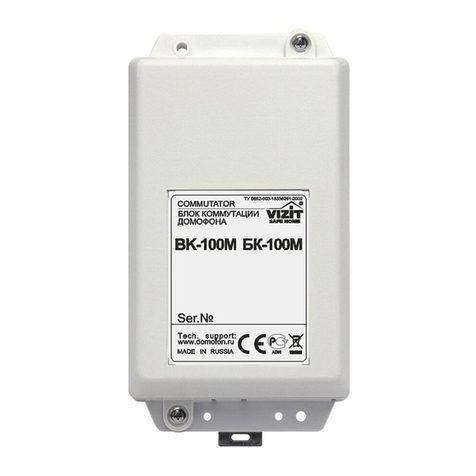
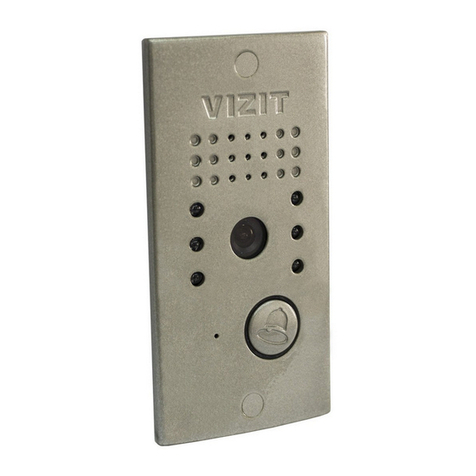
Figure Example of configuration diagram with two Power Supply Units BPD8 - 24/12-1-1.
BK MVE No-4 1
BK MVE No 4-4
2
BPD24/12-1-1
2
To monitors
BK MVE No 5-4
BK MVE No 8-4
2
BPD24/12-1-1
2
1
Conductor connecting
GND terminals of
power supply units
To monitors
To monitors
To monitors
www.vizit-group.com BK-4MVE Operating Instruction (revision 6 12 8 8201 - ) /
Table of contents
Other ViziT Intercom System manuals

ViziT
ViziT BVD-401 Series User manual

ViziT
ViziT BVD-342 User manual

ViziT
ViziT BVD 10CBL User manual

ViziT
ViziT BVD-405A-4 User manual

ViziT
ViziT BVD-411 Series User manual

ViziT
ViziT BK-30M User manual

ViziT
ViziT BVD-343 Series User manual

ViziT
ViziT BVD-405A-2 User manual

ViziT
ViziT M430C User manual

ViziT
ViziT BVD-406 Series User manual

ViziT
ViziT BVD-403 Series User manual

ViziT
ViziT BVD-431DXKCB User manual

ViziT
ViziT UKP-12-1 User manual

ViziT
ViziT VIZIT-M441MG User manual

ViziT
ViziT BVD-407 Series User manual

ViziT
ViziT BVD-343R User manual

ViziT
ViziT UKP-12-1 User manual

ViziT
ViziT 300 Series User manual

ViziT
ViziT MK-405 User manual

ViziT
ViziT МТ460СМ User manual