SystemBase CS-LAN User manual

User Manual
www.sysbas.com
CS-LAN
Version 1.0.1 2015/07/12

1
Revision History
Revision Date
Document Version
Pages
Description
July. 20. 2015
1.0
All
Initial release

2
Contents
Chapter 1 Overview 4
About this Manual 4
Reader 4
Documents 4
Technical Supports 5
Chapter 2 Getting Started 6
Overview 6
Features 6
Application 8
Chapter 3 Hardware Specifications 10
Hardware 10
LED 10
Serial Port Pin Specifications 11
Chapter 4 Connecting Network 12
Before Connecting 12
First-time Use 12
Making Connection 12
Chapter 5 Setting via Web 14
Access 14
Network Setting 14
Serial Setting 16
Change ID/PW 19
Reboot 19
Chapter 6 Utility-based Setting 20
Search 20
Settings 20

4
1. Overview
This chapter is intended to provide the CS-LAN related data, one of the serial converter device manufactured by
SystemBase.
About this Manual
This manual is intended to describe the connection and communication, setting and other managements regarding
the CS-LAN.
Reader
This manual was prepared for the users of CS-LAN. It is recommended to thoroughly read and understand this
manual prior to using or setting the CS-LAN. This manual includes the application of hardware level and settings of
software level. This manual is intended to help the users to easily control and manage the device to be connected
with CS-LAN.
Documents
The technical documents related to CS-LAN are listed as follows.
Please visit http://www.sysbas.com/ to download the CS documents, as well as the latest software and firmware. You
can be also provided with the technical support via FAQ or board.
Document
Description
CS-LAN Spec Sheet
CS-LAN Specifications
CS-LAN White Paper
General overview of convertor, description of background and
technology, and market environment
All documents provide the latest version at the homepage. The contents of document can be modified without a prior
notification.
Document
Description
User Manual
Description of integration, settings and management of CS-LAN
COM Port Redirector
User Manual
Description of the uses of SystemBase COM Redirector
TestView User Manual
Description of TestView – Comport, TCP and UDP test program
SGConfig Manual
Description of utility uses

5
Technical Supports
SystemBase provides technical support through two methods below:
1. Send an e-mail to our technical support team at [email protected]om to receive fast responses. Any questions,
requests, suggestions or comments are welcomed.
2. For instant response, call us. Our technical team will always provide detailed consultation and guides through a
simple phone call.
The phone number is: +82-2-855-0501 (ext. 233)
Available from Monday to Friday, 9:00 ~ 18:00 KST. We are closed on weekends and holidays.

6
2. Getting Started
This chapter provides the overview and core function of CS-LAN, and its package composition and application field.
Overview
CS-LAN is microscopic wire convertor that provides Ethernet wire communication to equipment supporting RS232.
The communication specification supports IEEE 802.3 10/100Base-TX and amounts RS232 standard DE9 connector,
thereby providing the serial communication speed at the highest 921.6Kbps and Ethernet communication speed at
100Mbps. A CS-LAN is the device that connects the remote control, monitoring and various types of serial devices
in the device connected via network.
Features
The basic features of CS-LAN are as follows. Other functions are also described throughout this manual.
-Serial communication speed at the highest 921 Kbps
-RS-232 method
-10/100 Mbps(Auto MDIX) Ethernet Port
-COM Port Redirector
-Web-based device settings
-SGConfig utility-based settings

7
Contents of Package
The CS-LAN package is composed as follows. Check if all components are included in the package.
CS-LAN device unit 1
5V DC Adaptor
Ethernet Cable
CS-LAN User Manual
Class A equipment
Sellers or users should be aware of the fact that this device is intended for industrial use(Class A),
not for residential use.

8
Application
CS-LAN can be applied in various fields.
Network Serial Communication
As the most common example of application, The PC and CS-LAN are connected to a network so the serial devices
connected to CS-LAN can be used in the PC.
Serial Communication Tunneling
A serial cable connected between the PC and serial device is extended to network so it can be used as a serial
cable (without distance limits). In order to use this function, please refer to the serial settings in the Chapter 5
Setting via Web to set at TCP Server – TCP Client or UDP Server – UDP Client mode. At these two modes, the
data can be received and sent.

9
COM Port Redirection
Using a redirection to use the serial port of CS-LAN connected to network as the serial port mounted on a PC.
Factory / Industrial Automation
PLC, Robot, Arm, Human-Machine Interface, Logistics storage rail
Medical device, tester controller
Alarm
Home appliance / electronic device
Power managing device, game console
Measuring equipment, gas detector, and water level and contamination measuring equipment
Data collector and distributor
Finance / Building Automation
Card reader, barcode scanner, Kiosk, POS related equipment
Serial printer, cash withdrawal, credit card reader
Biometric sensor security equipment

10
3. Hardware Specifications
This chapter is intended to provide a comprehensive information of hardware, including hardware composition of CS-
LAN, pin specification and other related matters.
Hardware
Serial Port: RS232(DE-9 FEMALE)
Power Connector: To connect a DC 5V adaptor power cable via DC Adapter.
Reset Button: Press and release a button to restart CS-LAN
LED: Indicate the operation of CS-LAN. The next chapter provides each LED functions from the LED states.
LAN Port: This port (8-pin RJ45) is used in connecting CS-LAN with Ethernet card, hub, router and other wire
network connector.
LED
LED Name
State
Operation
1
RDY
Blink
The light is turned on for a short period if power is on and turn
off at the completed booting.
2
TXD
Blink
Blinks at green light if sending serial data.
3
RXD
Blink
Blinks at red light if receiving the serial data

11
Serial Port Pin Specifications
RS-232
TXD
RXD
CTS
RTS DSR
5 4 321
98 7 6
DTR
GND
* CS-LAN is a DCE (Data Communications Equipment) converter that is directly connected to DTE equipment such as PC.
Pin No.
Signal
Description
2
RXD
Receive Data (Input)
3
TXD
Transmit Data (Output)
4
DTR
Data Terminal Ready (Output)
5
GND
Ground
6
DSR
Data Set Ready (input)
7
RTS
Request to Send (Output)
8
CTS
Clear to Send (Input)

12
4. Connecting Network
This chapter is intended to provide the required information to connect and operate CS-LAN with other serial device such as
Ethernet, serial connection of CS-LAN.
How to connect CS-LAN with a device and network is as shown in the follows.
Before Connecting
In order to connect a CS-LAN to network, a RJ45 Ethernet port is required. Ethernet supports 10Mbps and 100Mbps Ethernet
connection (automatic recognition of 10/100Mbps). A LAN port in CS-LAN supports a MDIX so that it automatically recognizes
the Ethernet crossover cable and straight through cable. Therefore, the type of cable connection is not a matter. The end of
cable is connected to CS-LAN and other network device.
First-time Use
The users need to check if the input voltage to be provided to CS-LAN to supply power correctly. CS-LAN is turned on and
starts rebooting only when the power is properly supplied.
RDY LED or TXD/RXD LED can be used to check the operation statue and please refer to the “Chapter 3 ‘composition of
hardware” for more detailed information LED states.
It requires an IP address in order to access CS-LAN web. Basically a static IP is given as default setting in CS-LAN. After first
access, enter other IP address manually or IP that is automatically assigned by DHCP server. This depends on the user’s
network configuration and policy but it is strongly recommended to assign a static IP to CS-LAN.
Making Connection
The users need to access web browser or use configuration utility in order to view or set the CS-LAN configurations. Please
refer to SGConfig manual for more detailed information how to use the utilities. This manual is prepared based on the settings
via web browser.
First the users need to know the network address, IP Address where the CS-LAN is being operated.
If LAN port of CS-LAN is used by IP assigned from DHCP or set on a fixed static ID address or unknown ID address, this
manual provides how to access the CS-LAN as follows.
Default IP Address: 192.168.0.223
The default IP address of CS-LAN is set on 192.168.0.223. In order to access this IP address, the network settings should
be changed. Please refer to the followings for setting.

13

14
5. Setting via Web
This chapter is intended to provide web settings for CS-LAN.
Access
Open a web browser and enter an IP address of CS-LAN to bring up the authentication window at the first access. Enter
“cslan” in ID and “99999999” in password to bring up a web setting page.
Network Setting
The first page displays the network setting for device network information.
It is as shown in the follows.
The network configurations and network management are set in the network setting. After changing the settings, press a
[Submit] button to save the changes, and the system should be restarted via reboot menu in order to apply the changes to
the actual operation. If not saving the changes prior to exit, the changes will be lost.
If you have not saved the changes by pressing a [Submit] button, you can go back to the original before changes
applied by pressing a [Cancel] button.
The main functions of Network Setting page are as follows.

15
Menu
Default
Description
Device
Name
CS-LAN
To set the name of a device
MAC Address
Distinct Address
To show a MAC Address
Connection Type
Static
To select if static IP or dynamic IP assigned from DHCP is selected
IP Address
192.168.0.223
To set the current ID address
If connection type is a static IP, enter a direct IP address; if CHCP, the
current IP is assigned and unable to be changed.
Subnet Mask
255.255.255.0
To set the current subnet mask address
(If connection type is a static IP, enter the direct subnet mask address.
If connection type is DHCP, the current subnet mask address is
displayed but is not able to be changed.)
Gateway
192.168.0.254
To set the current gateway address
(If connection type is a static IP, enter the direct gateway address; if the
connection type is DHCP, the current subnet mask address is displayed
but is not able to be changed.)
DNS
168.126.63.1
To set the DNS (Domain Name Service) ID address

16
Serial Setting
The operation settings of serial port are set at the serial settings. After changing the settings, press a [Submit] button to save
the changes, and the system should be restarted via reboot menu in order to apply the changes to the actual operation. If not
saving the changes prior to exit, the changes will be lost.
If you have not saved the changes by pressing a [Submit] button, you can go back to the original settings by pressing
a [Cancel] button
The current serial settings will be ignored at the COM Redirector mode and changed to settings at the connection to virtual
COM port.
In the COM Redirector mode, the current serial settings will be ignored and changed to settings at the connection to virtual
COM port will be applied.
Key functions of Setup Menu are as follows.

17
Menu
Default
Description
Operation
Mode
COM Redirector
To set the operating protocol to be used in the serial port.
COM Redirector
To enable serial port of CS-LAN at the Windows 2000/XP/2003/Vista/7/8.1 in
the PC with as a virtual COM Port. If you select this mode, all settings of serial
will follow the virtual COM port.
TCP Server
CS-LAN plays a role as a socket server to standby for accessing from client on
the network. The socket number is set at the [Local Port] and once the socket
access is completed, the data generated between the socket and the serial
port will be transferred as it is.
TCP Client
CS-LAN plays a role as a socket client when a specific server standbys for
accessing on the network. It attempts acceding with IP address and socket
number of the server. Once socket access is completed, the data generated
between the socket and the serial port will be transferred as it is. The OP and
port number to be requested for access should be set at [Target IP/Port].
UDP Server
CS-LAN plays a role as UDP server to standby for UDP access from client on
the network.
Socket number standbys for accessing is set the [Local Port].
If UDP package is received from the socket number, the data is to be sent to
serial port data and the data input from the serial port is to be sent to client in
UDP package form.
UDP Client
Once the data is input at the serial port, the IP and socket number of server is
to send the UDP package. The IP and port number of server requested for
accessing are to be set at [Target IP/Port].
Local Port
4001
To assign the socket number assigned to a port. This port is used to standby
for network socket connection at the TCP Server and UDP Server modes.
Target IP
0.0.0.0
To assign an IP address for device to be connected at the TCP Client and
UDP Client modes.
Target Port
4001
To assign a port to be connected at the TCP Client and UDP Client modes.
Latency
Time
0
To send the data consecutively received from the serial port to socket at once.
For example, if 100-byte text is sent from the serial device and then to socket
in the server via CS-LAN, the data being input by several byte unit is
immediately sent to a server through a socket if the value is 0, assuring a real
temporality. However, the disadvantage is to cause the potential traffic on the
network due to numerous packet being sent to server.
If this value is set at other than 0, the data being received at several bytes at

18
Menu
Default
Description
once is to be buffered and stood by at the set time prior to rereading. If there’s
new data received, it will fill the buffer again but if not, all received data will be
sent to a socket at once; therefore, no traffic issue is caused but is not to
assure its real temporality.
(Setting range: 0 ~ 255)
Baud Rate
9600 bps
To set the communication of serial port.
(Option: 150, 300, 600, 1200, 2400, 4800, 9600, 19200, 38400, 57600,
115200, 230400, 460800, 921600 bps)
Data Bits
8
To set the number of bit composing a byte.
(Option: 5, 6,7,8)
Stop Bits
1
To set the number of stop bits.
(Option: 1, 2)
Parity
No
To set a parity check.
(Option: No, Odd, Even)
Flow
Control
None
To set the flow control
(Option: None, RTS/CTS)

19
Change ID/PW
The ID and password are required to access the web setting page. This ID and password can be changed by user in the
following screen. Please be aware that this setting is saved and applied at the same time without rebooting.
Reboot
A device is restarted.
If you change the settings and save them via a submit button. The CS-LAN is restarted with the changes.
Table of contents
Other SystemBase Media Converter manuals
SystemBase
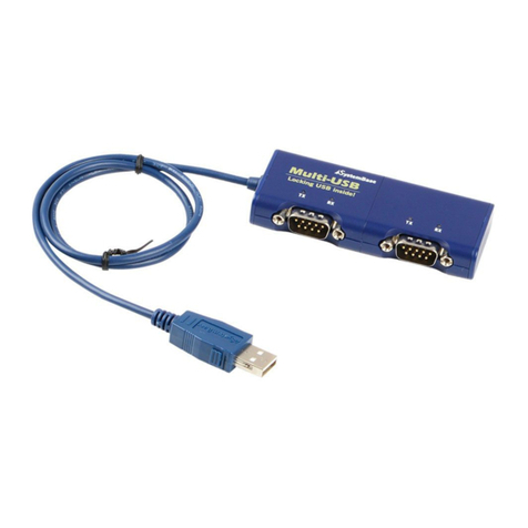
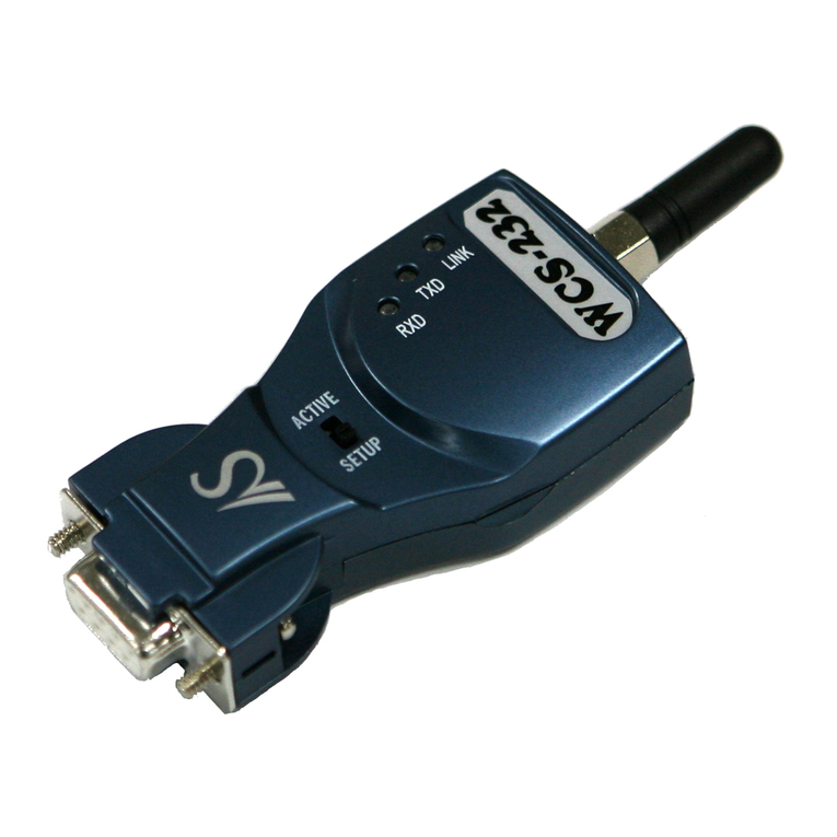
SystemBase WCS-232 v4.0 User manual

SystemBase
SystemBase SWIFIALLV10 User manual

SystemBase
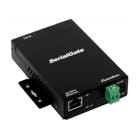
SystemBase SerialGate 2000 Series User manual

SystemBase
SystemBase sLAN/all-PoE User manual

SystemBase
SystemBase BT-232 User manual

SystemBase
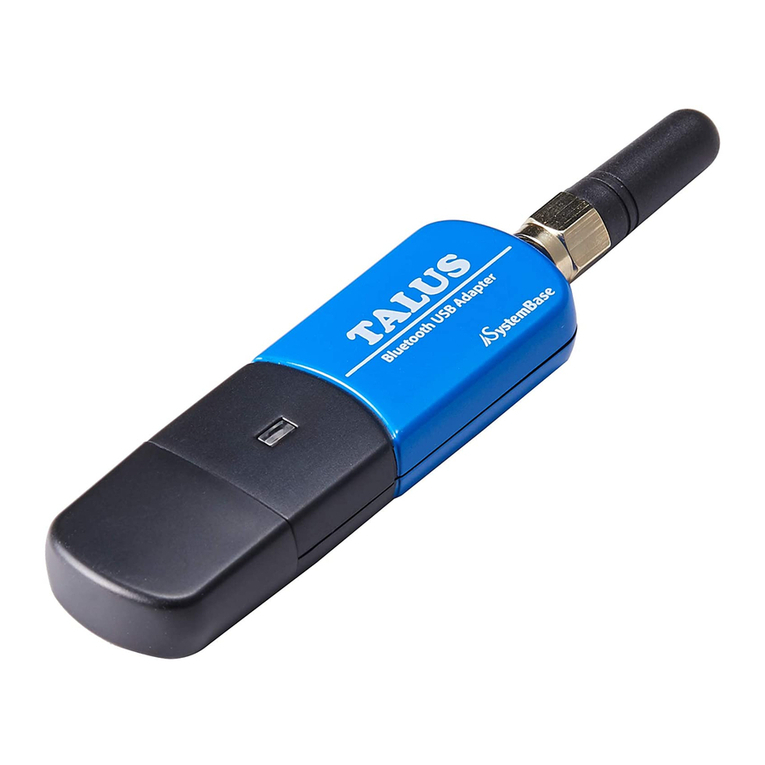
SystemBase TALUS User manual

SystemBase
SystemBase Multi-4U Ver1.7 User manual

SystemBase
SystemBase SerieslGate SG-1010/232 User manual
Popular Media Converter manuals by other brands

Speaka Professional
Speaka Professional 989340 operating instructions

Patton electronics
Patton electronics 2040 Series user manual

SEO Electronics
SEO Electronics CANeasy Installer manual

EuroLite
EuroLite Node 8 user manual

Algam Lighting
Algam Lighting SPLIT DD8 User manuals

Audiolab
Audiolab M-DAC User instructions