manuals.online logo
Brands
  1. Home
  2. •
  3. Brands
  4. •
  5. VOLKTEK
  6. •
  7. Switch
  8. •
  9. VOLKTEK IEN-8428P-24V User manual

VOLKTEK IEN-8428P-24V User manual

-1- -2- -3-
Quick Installation Guide
1. Overview
2. Package Checklist
4. Mounting and Dismounting to DIN-Rail
5. Cabling RJ45
3. Hardware Installation Procedure
STEP 1:
Unpack the device and other contents of the package
STEP 2:
Attach the DIN Rail Kit as shown in picture.
IEN-8428P-24V is equipped with eight 10/100/1000Base-T
ports plus two 100/1000Base-SX/LX SFP slots. IEN-8428P-24V
is a scalable, cost-eective and future-proof industrial
grade unmanaged PoE+ switch.
IEN-8428P-24V is a full Gigabit Ethernet switch supporting
IEEE 802.3at/803.3af on ports 1 to 8 i.e. it transmits
both power and data transmission over single Ethernet
cable for PoE appliances and devices. IEEE802.3at PoE+
support with total PoE power budget 240W when
input voltage is 48VDC or 120W when input voltage is
24VDC. The switch operates in wide temperature
range -40˚C~70˚C making it tough to suit for any factory
condition.
Open the package of the IEN-8428P-24V and carefully
unpack it. Check the contents of the package for the
following items*:
 IEN-8428P-24V Switch x 1
 DIN-Rail kit x 1
 Quick Installation Guide x 1
* Contents of the package can be adjusted based on
customer demand.
STEP 3:
Connect 24~57VDC power to terminal block. (Check
the polarity while connecting)
STEP 4:
Connect the Ethernet (RJ45) cable to the networking
device and check the LED status to conrm the connection
is established
Mounting the switch
Place the IEN-8428P-24V on the DIN rail from above using
the slot. Push the front of the switch toward the mounting
surface until it snaps into place with a click sound.
Dismounting the switch
Press the switch from top and pull out the lower edge of
the switch and then remove the switch from the DIN rail.
DIN-Rail-mounted with IEN-8428P-24V
Mounting the Switch Removing the Switch
Connect one end of an Ethernet/RJ45 cable into Ethernet
port of IEN-8428P-24V and other end to attached
networking device.
Ports 1-8 of the switch support Fast Ethernet as well as
Gigabit Ethernet (10/100/1000Base-T)
All the RJ45 ports on the IEN-8428P-24V support auto
negotiation and auto MDI/MDI-X to eliminate the need for
crossover cabling.
Note: Category 5e cable or above should be used.
IEN-8428P-24V
5678
5
6
7
8
SFP SFP
Wall Mount Kit
(Optional)
DIN Rail Kit
DIP Switches
Power Input
Terminal Block
Grounding
Screw
+
PWR
+
RPS
ALM
Reset
-4- -5- -6-
6400-000115
PWR
RPS
7. LED Indicators
ON: Primary power alarm reporting is enabled
OFF: Primary power alarm reporting is disabled
ON: Redundant power alarm reporting is enabled
OFF: Redundant power alarm reporting is disabled
Storm
QoS
ON: Broadcast/DLF storm control is enabled
OFF: Broadcast/DLF storm control is disabled
P9
100FX
ON: Port 9 link speed is set to 100Base-FX
OFF: Port 9 link speed is set to 1000Base-SX/LX
P10
100FX
ON: Port 10 link speed is set to 100Base-FX
OFF: Port 10 link speed is set to 1000Base-SX/LX
Illuminated
O
1000
(Green)
Illuminated Link on 1000Mbps
O Link on 100Mbps or 10Mbps
Illuminated
O
Illuminated
O
Illuminated PoE power is delivered to
powered device (PD)
O PoE power feeding doesn’t function
LNK/ACT
(Green)
Illuminated Ethernet port link-up
O Port disconnected or link failed
Blinking Data is transmitting / receiving
VOLKTEK, a quality brand from VOLKTEK Corporation,
warrants this product against detect in materials and
workmanship for a period of FIVE (5) YEARS to the
original purchaser.
If you discover a defect, VOLKTEK will, at its sole option,
repair or replace the product at no charge to you, provided
that you contact VOLKTEK technical support to obtain a
Return Merchandise Authorization Number (RMA) and
instruction on how and where repairs can be made.
This warranty does not apply if the product has been
damaged by accident, abuse, misuse, misapplication,
neglect, re, water, lightning or other acts of nature,
failure to follow supplied instructions, installation or
removal, have been repaired or have undergone attempted
repair by unauthorized personnel without written
consent from VOLKTEK, modied, defaced, or has its serial
numbers removed. VOLKTEK reserves the right to use
remanufactured, refurbished, or used parts and
components in making warranty repairs.
Certain features of third-party software or hardware
designed for the host system may not be available when
used with this product. Accordingly, VOLKTEK does not
warrant that hardware or software will function error free
when used in conjunction with this product.
This warranty is in lieu of all other warranties, whether oral
or written, express or implied. All expressed or implied
warranties for this product, including the implied warranties
of merchantability and tness for a particular purpose are
limited in duration to the warranty period. No warranties
expressed or implied will applied after this period. VOLKTEK
shall not be liable for lost prots, damage to other property
caused by any defects of this product, or damages based
upon inconvenience, loss of product use, loss of time,
commercial use, incidental and/or consequential damages
for the breach of any expressed or implied warranty,
including damages to property, and to the extent permitted
by law, damages for personal injury, even if VOLKTEK has
been advised of the responsibilities of such damages.
If you have any further questions, please contact Customer
Support:
Website: www.volktek.com
Email: [email protected]
Tel: +886-2-8242-1000
Fax: +886-2-8242-3333
LIMITED WARRANTY
PWR
(Green)
RPS
(Green)
ALM
(Red )
Alarm for no Primary power or Low I/P
voltage
No alarm to report or DIP function is
disabled
Primary Power is connected
Primary Power failure or not available
Illuminated
O
SFP
(Green)
Data is transmitting / Receiving
Port disconnected or link failed
Redundant Power is connected
Redundant Power failure or not available
6.2. DIP Switch Setting & Reset Button
You can use “PWR” for Primary Power input and “RPS”
for Redundant Power Input.
To insert power wire and connect the +24~57V DC
power to the power terminal block, follow the steps
below:
• Use at-head screw driver to loosen the wire-clamp
screws
• Insert the corresponding wires into contacts
• Tighten the wire-clamp screws to prevent the wires
from loosening
6.1. Redundant Power Input
6. Power Input
Safety measures should be taken before connecting the
power cable.Turn o the power before connecting
modules or wires. The correct power supply voltage is
listed on the product label. Check the voltage of your
power source to make sure that you are using the
correct voltage. DO NOT use a voltage greater than what
is specied on the product label. Calculate the maximum
possible current in each power wire and common wire.
Observe all electrical codes dictating the maximum
current allowable for each wire size. If current exceeds
the maximum rating, the wiring can overheat causing
serious damage to your equipment.
Safety rst
!
Top view of Terminal Block is
shown in the gure below:
Terminal Block
24~57VDC
1
2
3
4
5
6
1
2
OFF ON
3
4
5
6
PoE
1st~8th
port
(Green)
ON: Port-based QoS enabled on P1&P2
OFF: 802.1p QoS enabled (default)
Other VOLKTEK Switch manuals

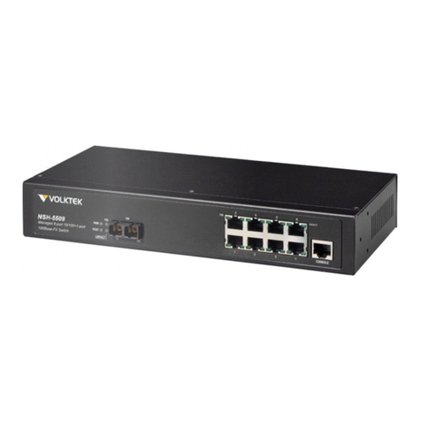
VOLKTEK NSH-5509 User manual

VOLKTEK

VOLKTEK NSH-5509 User manual

VOLKTEK NSH-5632 User manual

VOLKTEK

VOLKTEK NSH-5632 User manual

VOLKTEK NSH-9308P User manual

VOLKTEK

VOLKTEK NSH-9308P User manual

VOLKTEK INS-802 User manual

VOLKTEK

VOLKTEK INS-802 User manual

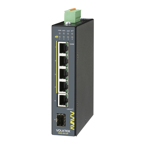
VOLKTEK HNS-8415P User manual

VOLKTEK

VOLKTEK HNS-8415P User manual

VOLKTEK NSH-9309 User manual

VOLKTEK

VOLKTEK NSH-9309 User manual

VOLKTEK INS-801W User manual

VOLKTEK

VOLKTEK INS-801W User manual

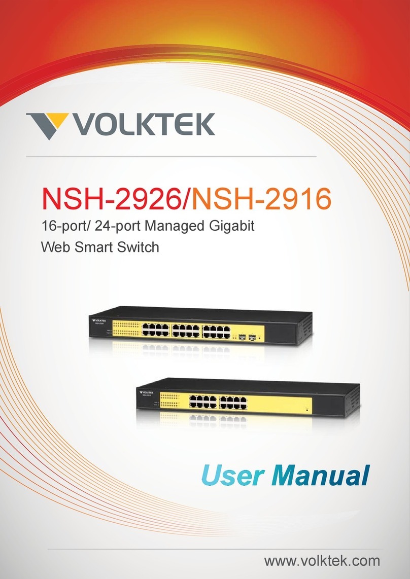
VOLKTEK NSH-2926 User manual

VOLKTEK

VOLKTEK NSH-2926 User manual

VOLKTEK INS-806 User manual

VOLKTEK

VOLKTEK INS-806 User manual

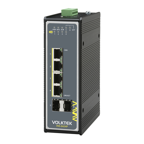
VOLKTEK INS-8424P User manual

VOLKTEK

VOLKTEK INS-8424P User manual

Popular Switch manuals by other brands

Transition Networks LAN MASTER 33022.B user manual

Transition Networks

Transition Networks LAN MASTER 33022.B user manual

Hydropa DS-1 Series operating manual

Hydropa

Hydropa DS-1 Series operating manual

D-Link xStack DGS-3620 Series reference guide

D-Link

D-Link xStack DGS-3620 Series reference guide

Kramer VS-4x4FW user manual

Kramer

Kramer VS-4x4FW user manual

Gems FS-600 Series Operating and installation instructions

Gems

Gems FS-600 Series Operating and installation instructions

Eaton LCS Instructional Leaflet

Eaton

Eaton LCS Instructional Leaflet

Cisco IE 4010 Hardware installation guide

Cisco

Cisco IE 4010 Hardware installation guide

Wöhner QUADRON 185Power manual

Wöhner

Wöhner QUADRON 185Power manual

ZyXEL Communications GS-4012F Specifications

ZyXEL Communications

ZyXEL Communications GS-4012F Specifications

Eaton TM-1-8240 Series Instruction leaflet

Eaton

Eaton TM-1-8240 Series Instruction leaflet

Sigma 2100 Series Operator's manual

Sigma

Sigma 2100 Series Operator's manual

HITROL HTM-20N Series instruction manual

HITROL

HITROL HTM-20N Series instruction manual

Repotec RP-PEG08-H user manual

Repotec

Repotec RP-PEG08-H user manual

Extron electronics SW USB Pro Series Setup guide

Extron electronics

Extron electronics SW USB Pro Series Setup guide

HP 6125XLG Configuration guide

HP

HP 6125XLG Configuration guide

Natec SILKWORM user manual

Natec

Natec SILKWORM user manual

JLCooper Electronics GangWay4 user manual

JLCooper Electronics

JLCooper Electronics GangWay4 user manual

Moxa Technologies EtherDevice EDS-30 Hardware installation guide

Moxa Technologies

Moxa Technologies EtherDevice EDS-30 Hardware installation guide

manuals.online logo
manuals.online logoBrands
  • About & Mission
  • Contact us
  • Privacy Policy
  • Terms and Conditions

Copyright 2025 Manuals.Online. All Rights Reserved.