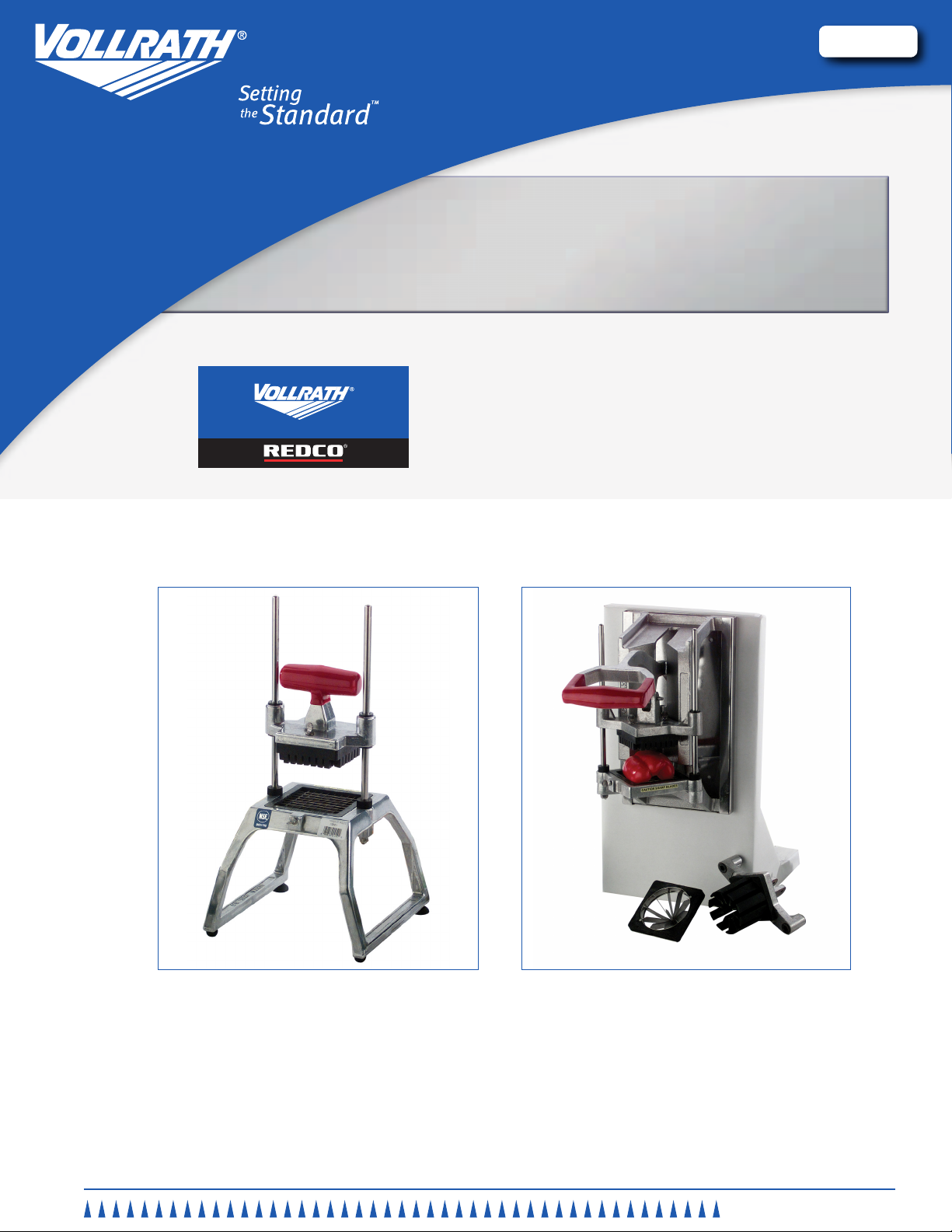
Manual Food Processing equiPMent
3
ENGLISH
OperatOr’s Manual
7. Using a strong, quick, downward thrust, force the food product through
the blade assembly.
8. Repeat this process until you have prepared enough food product for
your daily needs.
9. Clean and lubricate your equipment immediately after each use. See the
CLEANING section of this manual for more information.
Cleaning
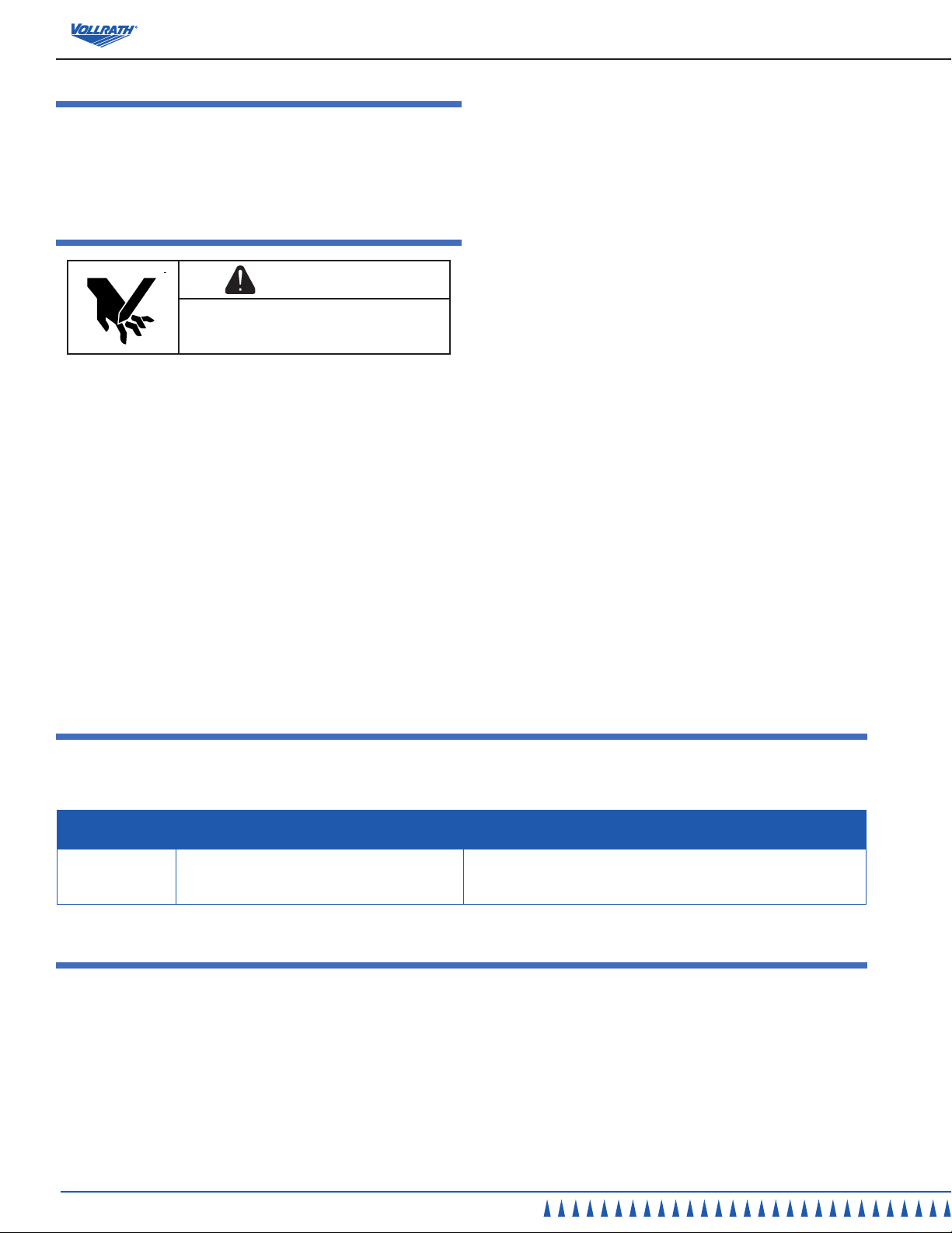
WARNING
Sharp Blade Hazard.
Blades are sharp and can cause cuts. To avoid
injury from sharp blades, handle with caution.
To maintain the appearance and increase the service life, clean your daily.
NOTE:
Food acids will make blades dull and corrode the metal.
Always clean this food preparation equipment immediately
after every use.
1. Remove the pusher head assembly:
Tabletop models. Slide the pusher head (D) off the rod guides (A).
Figure 1.
Wall mount models. Remove the pin (J). Lift the handle (B) and slide
the pusher head (D) off the guide rods (A). Place pin (J) back into the
hole on the handle assembly to prevent its loss. See Figure 2.
2. Raise the bumpers approximately (E) 2” (5.0 cm). See Figures 1 and 2.
3. Loosen the thumbscrew (F) and carefully remove the blade
assembly (H). See Figures 1 and 2.
4. Wipe, rinse or spray off equipment, pusher head and blade assembly
thoroughly with HOT water.
5. Do not wipe across the blades or use scrub pads on this equipment.
Wiping across the sharp edge of the blade can cause injury and will dull
the blades.
6. The cutting blade assembly is best cleaned by forcing water under
pressure through the blades from the unsharpened side. If necessary,
use a nylon bristle cleaning brush to push food particles out from the
unsharpened side of the cutting blade assembly.
7. Do not put this equipment in a dishwasher or dish machine with soaps,
detergents, or other alkaline chemicals that can harm the equipment.
8. After cleaning, let the equipment air dry.
9. Install the cutting blade assembly by inserting the tab on the blade holder
into the groove in the base, then lowering the blade holder into the
seated and ush position in the base. Tighten the thumbscrew (F).
10. Lubricate the guide bar with mineral oil or Petro Gel after each use.
Do not use cooking oil as it will become sticky and may permanently
damage the equipment.
11. Slide the bumpers (E) into place.
12. Install the pusher head assembly:
Tabletop models. Slide the pusher head (D) onto the rod guides (A).
Figure 1.
Wall mount models. Remove the pin (J) from its storage location on the
handle assembly. Lift handle (B) and slide the pusher head (D) on the
guide rods (A). Place pin back into the hole through the handle assembly
and the pusher head. See Figure 2.
E BUMPERS. Cushions the stop of the pusher head.
F THUMBSCREW. Used to secure the pusher head block or the
blade assembly.
G PUSHER HEAD BOCK. Pushes the food product through the
blade set. Specically sized to match the corresponding blade
assembly.
H BLADE ASSEMBLY. Houses the blades. Specically sized to
match the corresponding pusher head block.
I BASE ASSEMBLY. Holds the guide rods and blade assembly.
J LOCKING PIN. Secures the pusher head to the handle on wall
mount models.
unPaCking the equiPment and initial setuP
Carefully remove crating or packaging materials from the equipment. When
no longer needed, dispose of all packaging ,materials in an environmentally
responsible manner.
Installing the wall mounted model:
1. Use four (4) 1/4” screws of a suitable length to secure the base to the
wall. Install screws into studs. If this is not possible, use proper anchors
and screws to secure base .
oPeration
WARNING
Sharp Blade Hazard.
Blades are sharp and can cause cuts. To avoid
injury from sharp blades, handle with caution.
Prior to rst use, it is important to clean the equipment. Wash new blades
with warm soapy water and rinse thoroughly to remove the thin protective oil
lm.
1. Before each use, check that the equipment is clean and the blades are
in good condition. If loose or broken blades are found, blades must be
serviced.
2. Before each use, always check for proper blade alignment. Slowly set
the pusher head (D) onto the blade assembly. See Figures 1 and 2. They
should slide together with no obstructions. If there are obstructions, verify
they are a matching set. Rremove the obstruction.
3. Verify that the blade assembly and pusher head assembly are the
desired size.
4. Prepare the food product to be processed. The maximum size of the food
product is 3-1/2” (8.9 cm) in diameter.
5. Lift the handle (B) and place the food on the blade assembly with the at
side down.
6. Remove hand from the blade assembly area and place that hand on the
leg of the base on table top equipment, or on the wall for wall mounted
models.