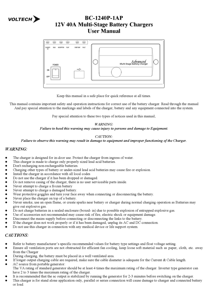
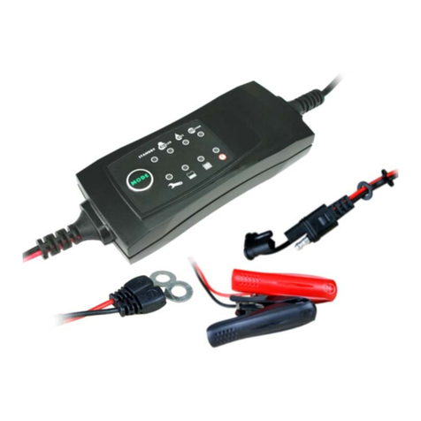
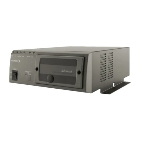
Voltech SBC-5925 User manual

SBC-5925: 3 STAGE DC-DC CHARGER.
DESIGNED TO CHARGE AUX BATTERIES WITH AND WITHOUT AN IGNITION TRIGGER.
NOTE:
BATCH STARTING WITH SERIAL#s G5016
VEHICLES WITH A LOW VOLTAGE CHARGE ALTERNATOR WILL ONLY BE ABLE TO USE THE AUTO START MODE IF THE
CHARGE VOLTAGE TO THE UNIT IS ABOVE 13.4V (START CHARGE = 13.4V (26.8V) STOP CHARGE = 12.8V (25.6V))
UNITS FROM THIS BATCH CAN STILL BE USED IF INPUT VOLTAGE IS < 13.4V BY USING THE IGNITION MODE
NOTE:
BATCH STARTING WITH SERIAL#s 1516
VEHICLES WITH A LOW VOLTAGE CHARGE ALTERNATOR CAN USE BOTH MODES. IF USING AUTO START MODE, CHARGE
VOLTAGE SOURCE MUST BE ABOVE 12.8V (START CHARGE = 12.8V (25.8V) STOP CHARGE = 12.2V (24.6V))
10 SECOND DELAY FOR ALL SET POINTS FOR THIS BATCH.
SPECIFICATIONS:
•9-32V input range (suitable for 12V or 24V input to 12V output but NOT 24V output):
•70 mA current draw on input side when not charging and unit on in AUTO START MODE.
CHARGING STATUS LED
BULK MODE (FAST FLASH): VOLTAGE WILL KEEP RISING UNTIL ABSORPTION VOLTAGE IS REACHED.
SOFT START: (FAST FLASH): IF IN FLOAT, OUTPUT IS 1.15A UNTIL BULK CAN BE REACHED, THIS IS IF OUTPUT BATTERY IS
LOW OR THERE IS A HIGH LOAD.
ABSORPTION MODE (SLOW FLASH): VOLTAGE WILL STAY CONSTANT AT SET POINT AND CURRENT WILL DECREASE
FLOAT MODE (SOLID): VOLTAGE IS CONSTANT, AND CURRENT IS MINIMAL
LITHIUM FLOAT MODE (OFF): LITHIUM STOP CHARGE
NOTE: FLOAT VOLTAGE ONLY FOR BATCH STARTING WITH SERIAL#s 1516 IS 0.5V LOWER THAN TABLE FIGURES
Rated output power
20A at 13.8VDC
Efficiency
90%
Output (Charge) Voltage
Battery Type
Absorption
Float
Wet
14.4
13.3
AGM
14.3
13.2
GEL
14.0
12.9
CAL
15.1
14.0
LiFePO4
14.8
STOP
Size (L x W x H)
130 x 188 x 55mm
Weight
Approx. 870g

OUTPUT VOLTAGE LED
FAST FLASHING: Output Voltage between 12.5V & 13.5V
SLOW FLASHING: Output Voltage <12.5V
SOLID: Battery Voltage > 13.5V
FAULT LED
No input Voltage present.
Input Voltage out of range.
Fault in unit.
AUTO START MODE:
Low voltage Disconnect <9V Input
BATCH STARTING WITH SERIAL#s G5016
Start Charge: 13.4V (26.8V for 24V) input
Stop Charge: 12.8V (25.6 for 24V) input
BATCH STARTING WITH SERIAL#s G1516
Start Charge: 12.8V (25.6V for 24V) input
Stop Charge: 12.2V (24.4V for 24V) input
IGNITION MODE:
Low Voltage Disconnect <9V Input (18V for 24V) input
Low Voltage Reconnect: > 11V (22V for 24V) Input
CONNETION:
1. The unit is in auto start mode by default.
2. connect both input and output to the unit.
3. Unit can take input from either a 12V or 24V vehicle.
4. Or you can take a Voltage signal 12V or 24V from any source.
5. The unit will always start in bulk mode when connected or mode changed (refer to Charging status LED)
6. 1 min delay for Start Charge & 10 sec delay for Stop Charge in AUTO START MODE. 10 sec delay in IGNITION MODE
7. IGNITION MODE ONLY: Apply 9-32V to ignition pin, the unit will go into IGNITION MODE. THE SETTING WILL BE
SAVED UNTIL RESET.
BATTERY SELECTION:
1. Hold down the Battery Select button for 5 seconds until the LEDs flash
2. Only the battery type combination of LEDs as below will flash (not all 3)
3. Wait for 10 seconds for the LEDs to stop flashing.
4. The battery type is now saved.
LITHIUM:
•This unit is suitable for LiFePO4 batteries
•The float is set to stop charge. The output will pulse in this mode.

AUTO START MODE:
1. DISCONNECT IGNITION PIN: IF IN IGNITION MODE, UNIT WILL NOT CHANGE TO AUTO START IF THERE IS VOLTAGE
ON IGNITION PIN.
2. Hold down the Battery Type Select button for more than 15 sec.
3. ALL A.B.C. LEDs will flash, and the unit will stop charging while they are flashing.
4. Release the button, the unit will then charge in AUTO START MODE.
5. THE SETTING IS SAVED UNTIL VOLTAGE IS APPLIED TO THE IGNITION PIN.
6. The unit will operate ONLY at the pre-set Voltages.
7. The unit will not charge below Stop Charge Voltage.
8. AUTO START MODE not suitable for Vehicles with low Voltage Charging systems < 12.8V charge.
(use IGNITION MODE) or (OK FOR VEHICLES > 12.8V CHARGE OR OK FOR BATCH STARTING WITH SERIAL#s 1516)
IGNITION MODE:
1. To change to IGNITION MODE supply 9-32V to the ignition pin (at any time, even in AUTO START MODE)
2. There is no need to Press and hold the Battery Select button for this mode.
3. THE SETTING IS SAVED UNTIL THE UNIT IS RESET TO AUTO START MODE.
TERMINAL BLOCK
+V IN: The V+ pin has the same voltage as the input terminal (+/- 0.2V, you can trigger the unit and use a relay without
running power all the way to the trigger source.
IGNITION: Ignition trigger wire.
GND: Ground pin for Remote Display. Connect to display black wire.
ALARM: Alarm output pin. Alarm output voltage equals to system input voltage with max 200mA current.
YELLOW: Connect to display yellow wire.
GREEN: Connect to display green wire.
RED: Connection to display red wire.
T+: Not used.

FEATURES
●3 Stage charge
●2 Stage charge for LiFePO4 batteries.
●9-32V input for either 12V or 24V input
●Charge AUX batteries from long distance charge source.
●Ignition Control feature.
●Low Voltage Cut Off Protection for starting battery.
●Auto Reset Input Under Voltage Protection.
●Auto Reset Output Over Voltage Protection.
●Auto Reset Over Temperature Protection.
●Auto Reset Overload Protection (C.C.) with constant current at decreased output voltage.
PROTECTIONS:
●Input under voltage protection
●Output Over voltage protection
●Overload protection
●Over temperature protection
TROUBLESHOOTING GUIDE:
IT IS RECCOMENDED THAT THE UNIT BE CHECKED BY A QUALIFIED PERSON. READ ALL INSTRUCTIONS AND
NOTES CAREFULLY BEFORE CALLING ELECTRO PARTS AUST PTY LTD.
ALL MEASUREMENTS MUST BE TAKEN AT TERMINALS OF UNIT NOT AT BATTERIES.
NO OUTPUT:
SOLUTION:
•IGNITION MODE: If there has been a Low Voltage Disconnect condition, there will be no output until the input
Voltage reaches above Low Voltage Reconnect, even if the ignition source has been turned off and back on again.
•Check charging status mode if solid green and output Voltage is higher than 12.6V Unit will be in float mode.
•Load the output battery to check that current flows.
•Check the input and output connections.
•Check the input Voltage and compare to Start Charge setting and low Voltage Reconnect.
•Check what mode the unit is in. Unit may be in IGNITION MODE, check if Input Voltage is above set point.
•Check all wires are connected properly without a loose connection including ignition pin.
•Check input and output fuses inside.
FAULT LIGHT:
SOLUTION:
•Fault will be on if there is no connection or Voltage to input but there is to connection to output.
•Fault will be on if the input Voltage is below the start charge Voltage.
•Fault will be on if the input Voltage is below Low Voltage Disconnect.
•Fault is on, If Low Voltage Disconnect occurs and the input is still not above Low Voltage Reconnect.
•Check that input Voltage is above the start charge setting.
•Check that the input Voltage is above the Low Voltage Disconnect.
•If input has reached below Low Voltage Disconnect, check that the input is above Low Voltage Reconnect.
•Check all connections, fuses or circuit breakers.
•Check that input and output are wired up correctly at unit.
OUTPUT VOLTAGE PULSING:
SOLUTION:
•This is for lithium setting only. There is no float, but the unit will pulse high Voltage and switch off. Output
Voltage will drop until the unit pulses again. (every 5 sec. approx.)
•Check the battery type has been selected correctly.
UNIT CUTS IN AND CUTS OUT:
(FAULT LIGHT SOLID THEN GOES OUT AND THEN CHARGING STATUS BLINKS FAST, SLOW OR SOLID)
SOLUTION:
Note: if the unit starts charging and the input Voltage drops below 9V (because of the battery on the output is being
charged or there is high load) this brings the Voltage down, the unit will disconnect. When disconnected. The input is not
under load, the input voltage will rise and if it goes above the Start Charge Voltage in AUTO START MODE or Low Voltage
Reconnect in IGNITION MODE, the unit will then reconnect.
The 10 second delay still applies. This means that, if the battery on the output is very low, or the load is high, the unit will
cut in, and then cut out. This is until the input can get the output battery Voltage high enough to keep the input Voltage
above the Cut in setting. (see below for solution)
•This is not a fault of the unit.
•The unit starts in bulk mode AND input is below Cut out Voltage (as the input and output are paralleled the
overall input Voltage will drop depending on the charge source)
•This is caused by either low voltage or low current input or very flat battery or high load on output.
•Check input Voltage and current at terminals.
•Make sure cable is correct size to avoid Voltage drop for the distance of the cable.
•Make sure that the charge source is supplying enough current on the input terminals.
•Check all connections.
•Increase input voltage or check for voltage drop.
•Reduce load.
•Wait for battery voltage to rise.
NO BATTERY VOLTAGE LEVEL ON DISPLAY REMOTE:
SOLUTION:
•Display will not show the Battery Voltage level when there is a load on the battery
•Check connections at green terminal block.
CHECK ALL TROUBLE SHOOTING AND NOTES.
IF YOU THINK THE UNIT IS FAULTY, DO NOT REPLACE WITH ANOTHER UNIT.
EMAIL ELECTRO PARTS FOR WARRANTY ENQUIRIES FIRST.
[email protected]om.au
Return for warranty assessment:
Electro Parts Australia Pty Ltd
51 Southlink St
PARKINSON, QLD 4115
www.electroparts.com.au
Electro Parts Rev 1.0 5925
Table of contents
Other Voltech Batteries Charger manuals

Voltech
Voltech BC-2407HT User manual

Voltech
Voltech BC-1230P User manual

Voltech
Voltech SBC-1205 User manual

Voltech
Voltech BC-1240P-1 User manual

Voltech
Voltech BBC-3140 User manual

Voltech
Voltech BC-1230P User manual

Voltech
Voltech BC-2415P User manual

Voltech
Voltech BC-1240P-1AP User manual

Voltech
Voltech SBC-2403 User manual
Popular Batteries Charger manuals by other brands

EVBox
EVBox BusinessLine installation manual

Outback Power Systems
Outback Power Systems EXTREME OBX-IC2024S-120 owner's manual

fontastic
fontastic GaNto35 user manual

William Sound
William Sound CHG 408 installation instructions

Samlexpower
Samlexpower Evolution EVO-1212F owner's manual

Inter-m
Inter-m PB-9207A specification