Voltech BC-1230P User manual

BC-1230P/ 1240P/ 1260P
Multi-Stage Battery Chargers
User Manual
Keep this manual in a safe place for quick reference at all times.
This manual contains important safety and operation instructions for correct use of the battery charger. Read through the manual
And pay special attention to the markings and labels of the charger, battery and any equipment connected into the system.
Pay special attention to these two types of notices used in this manual;
WARNING:
Failure to heed this warning may cause injury to persons and damage to Equipment.
CAUTION:
Failure to observe this warning may result in damage to equipment and improper functioning of the Charger.
WARNING:
●The charger is designed for in-door use. Protect the charger from ingress of water.
●This charger is made to charge only properly sized lead acid batteries.
●Don't recharging non-rechargeable batteries.
●Charging other types of battery or under-sized lead acid batteries may cause fire or explosion.
●Install the charger in accordance with all local codes
●Do not use the charger if it has been dropped or damaged.
●Do not remove casing of the charger, there is no user serviceable parts inside.
●Never attempt to charge a frozen battery
●Never attempt to charge a damaged battery.
●Wear protective goggles and turn your face away when connecting or disconnecting the battery.
●Never place the charger on top of a battery.
●Never smoke, use an open flame, or create sparks near battery or charger during normal charging operation as Batteries may
give out explosive gas.
●Do not charge batteries in a sealed enclosure (boxed- in) due to possible explosion of entrapped explosive gas.
●Use of accessories not recommended may cause risk of fire, electric shock or equipment damage.
●Disconnect the mains supply before connecting or disconnecting the links to the battery.
●If the charger does not work properly or if it has been damaged, unplug its AC and DC connection.
●Do not use this charger in connection with any medical device or life support system.
●This appliance is not intended for use by persons (including children) with reduced physical, sensory or mental capabilities, or
lack of experience and knowledge, unless they have been given supervision or instruction concerning use of the appliance by a
person responsible for their safety.
●Children should be supervised to ensure that they do not play with the appliance.
●Battery chargers for charging automobile batteries shall not be fitted with natural rubber-sheathed supply cords.
CAUTIONS:
●Refer to battery manufacturer’s specific recommended values for battery type settings and float voltage setting.
●Ensure all ventilation ports are not obstructed for efficient fan cooling, keep loose soft material such as paper, cloth, etc. away
from the Charger
●During charging, the battery must be placed in a well ventilated area.
●If longer output charging cable are required, make sure the cable diameter is adequate for the Current & Cable length.
●AC source from portable generator:
The VA rating of a standard generator should be at least 4 times the maximum rating of the charger.
How-ever, Inverter type generators need to have only 2 to 3 times the maximum rating of the charger.
●It is recommended that the ac output is stabilized by running the generator for 2-3 minutes before switching on the charger.
●This charger is for standalone application only, parallel or series connection with another charger may cause damage to charger
and connected battery.
●AC supply cord (leads) should be at least minimum size of 3G 0.75mm2 nominal cross-sectional area.

Introduction
Congratulations on purchasing our new Multi-Stage (IU0U) Switching Mode Battery Charger.
This series of advanced chargers use Micro-Processor to control the charging profiles and protective functions.
The special charging programs are designed to charge both stand alone battery and battery with connected loads.
Innovative charging profiles blend in with the ever changing “state of charge” of the batteries to give just the right amount of
current and voltage so your batteries will not be under or over charged. There are 8 sets of selectable charging profiles
specifically designed for a wide range of Wet, Gel, AGM, LiFePO4, Calcium-Calcium and now also Lead Crystal batteries.
There are also two User programmable charging profiles for the professional users via the USB port by personal computer.
In addition, the programmed maintenance charge provides a timely Equalization charge for the Wet lead acid battery.
Almost all the protections are controlled by the Micro-Processor. On start-up, the charger runs a series of self-tests on the
protective functions, displays and critical components like the cooling fan.
The optional detachable Remote Control Panel provides exceptional monitoring of the batteries, charger output, protection status,
hours of operation, etc.
Intended Use:
All Automotive, Marine, Mobile Home, RV, Electric Scooters, Golf Carts, Solar, Deep Cycle, UPS Standby, Industrial &
Commercial Applications.
A. Control and Indicators

1. Power Switch
To turn ON and OFF AC power to charger
2. Charger status LED display
Charger ON LED (Green) : Lights up when power ON
Bulk LED (Red) : Bulk charging with Constant Current (max.)
Bulk LED (Red, Flashing) : Soft-Start Mode ( see Sec; F )
Absorption LED (Orange) : Absorption charging with preset Constant Voltage
Float LED (Green) : Float charging with preset Constant Voltage
Over Temp LED (Red) : Lights up when over temperature protection,
Flashing when current de-rating
Fault LED (Red) : Charger malfunction
(overload, output short circuit, reverse polarity, output over voltage protection)
3. Programming Port
Factory use only
4. Battery selection switch has pre-set profiles for,
- AGM, GEL, LiFePO4, Calcium-Calcium, WET (flooded), LEAD CRYSTAL,
& also 2x user defined program selections. (default setting is AGM Pos’ #4)
5. Charging current selection switch
Max charging current can be selected from 10% to 100%. Default setting is 100%. [see Sec. C]
6. USB port
Connect charger to a computer for utilizing ‘User define setting’ or Data logging upload [See Sec. P]
7. Remote display Port to connect to accessory HBR-3100 remote display
To remote display the charging Voltage, Current & charging status. Switch the charger output ON/OFF.
Also provides alarms & displays fault trigger, As well as enable manual Equalization for wet batteries.
8. Equalization mode selection switch, (Caution; for open top wet batteries only)
Can be selected by Manual or Auto. Default is OFF
9. Battery Connection / DC Output Terminal(s)
10. Automatic Cooling Fan
11. Inlet AC socket with Mains fuse holder
12. Temperature Sensor Socket
Connection to Battery Temperature sensor (accessory)
Sensor to increase / decrease charging voltage at low/ high battery temperature
B. Using the charger
1. Check the supplied accessories:
AC cord, Remote Battery temperature sensor, CD (software) & USB cable are with the package.
2. Remove the magnetic dummy remote control panel on the front of the charger to select the battery type and the max. output
(charging) current, you may need to ply it open to get a hold the edge of the panel in order to lift it out .
3. Battery Type Selection
Check against the Absorption and Float Voltage with the battery type and specifications given in section N.
Make sure the charger is power OFF.
Use a small slot type screw driver to select the battery through Battery Selection Switch (4).
AGM/GEL : Sealed type (VRLA), AGM-GEL, Maintenance Free, Automotive or Deep Cycle lead acid batteries
WET : Flooded Type lead acid batteries (to which water can be added) Automotive or Deep Cycle
Calcium-Calcium* : Sealed type (VRLA) Lead Acid batteries with Calcium content Automotive or Deep Cycle
LiFePO4 : Sealed type Lithium Iron Phosphate batteries (2 different settings available)
Lead Crystal : Sealed Lead Crystal batteries for cycling use (RV’s etc).
The selected battery type can be viewed at the optional remote panel.
4. *Warning; ONLY Calcium-Calcium type batteries are to be charged in this mode and only when a boost charge is required
(15.1Volts). NO loads are to be connected to the battery during this charge mode.
Charge through one cycle only then set the battery selector back to the WET setting.

C. Power Level adjustment
End users can Preset the maximum output (charging) current in 10% increments to make the charger suitable for different
Battery capacities &/or loading conditions.
Make sure the Main Switch is OFF before adjust the power level.
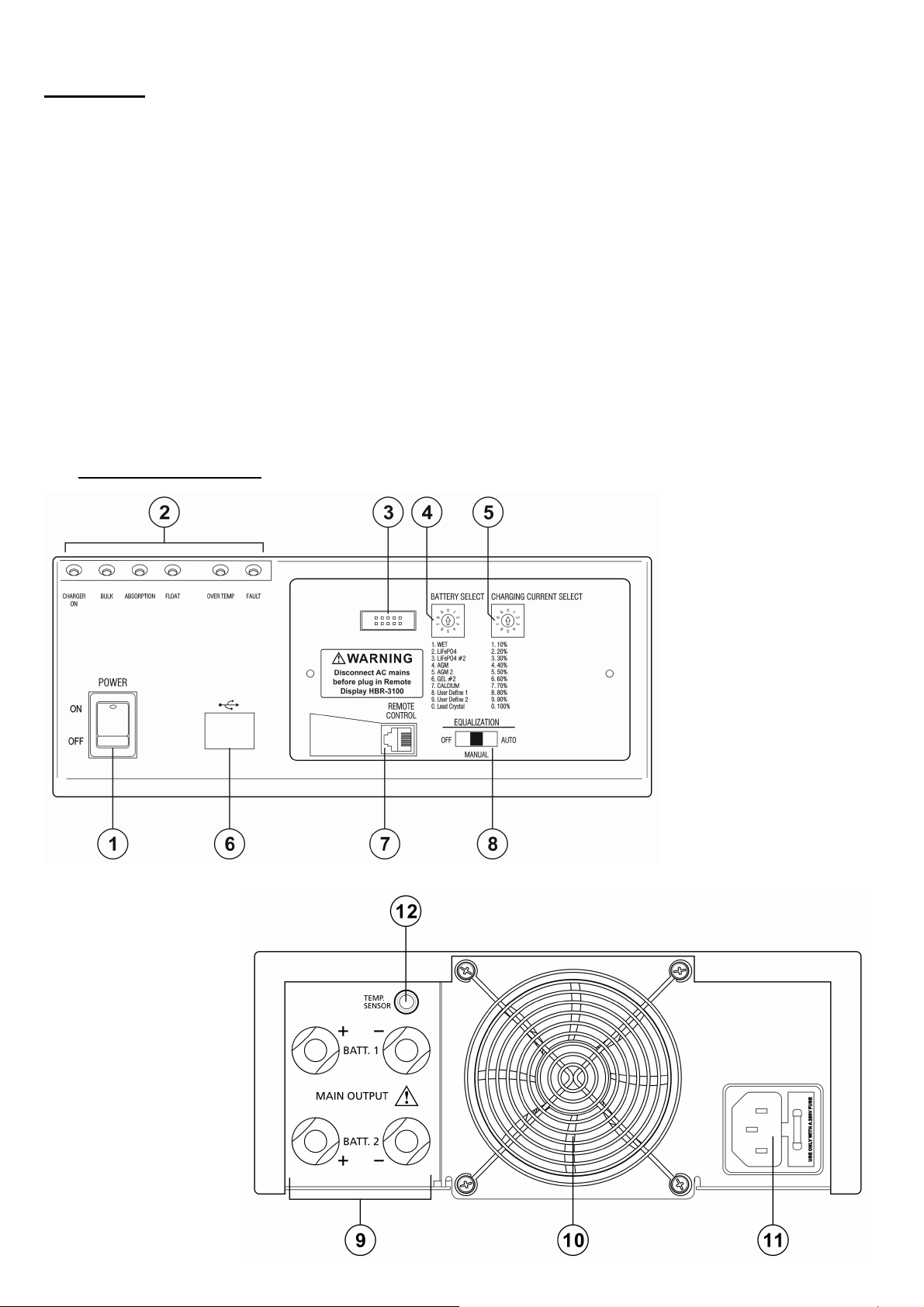
Use a small slot type screw driver to select the maximum output current via the Charging Current Selection Switch (5).
The selected max. output current can also be viewed on the optional remote panel (HBR-3100).
Position 0: 100% of the rated current
Position 9: 90% of the rated current
Position 8: 80% of the rated current
Position 7: 70% of the rated current
Position 6: 60% of the rated current
Position 5: 50% of the rated current (E.g.; a 40 Amp charger will be limited to 20Amp Max output at the 50% setting)
Position 4: 40% of the rated current
Position 3: 30% of the rated current
Position 2: 20% of the rated current
Position 1: 10% of the rated current
Recommended Battery Capacity
The extended range of AH capacity is based on the appropriate charging current selection 10% to 100%.
Some battery type can take higher charge current.
When in doubt, Always check with the battery manufacturer for recommended charging current.
Charger Model
BC-1230P , 30A
BC-1240P , 40A
BC-1260P , 60A
Battery Capacity
12 AH - 300 AH
15 AH - 400 AH
20 AH - 600 AH
D. Testing the charger with output open circuit (nothing connected to the output terminal)
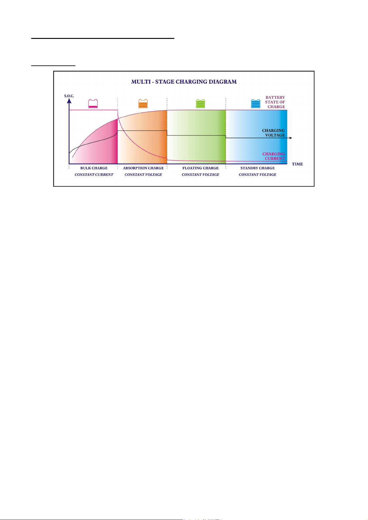
On power up, the charger will do a self-check during which all LED indicators are on & fan runs at full speed for a few seconds.
If Self-test was OK; Then the Charger On and the Absorption LED’s will stay on.
After 5 minutes (no load) the Float LED will be come on and Absorption LED off.
Remark: Power Supply Mode
You can connect Loads directly to the output terminal without a Battery and the charger will provide a constant DC source
Voltage according to the ‘Battery type’ and available ‘Output power’ (current) settings selected, (as detailed in Sections B3 & C.)
This feature is handy for caravan installer to check the operation of connected powered appliance or connections.
E. Battery Charger Installation and Connection
Observe the warnings & safety precautions before rushing to install and operate the charger.
Check battery condition, fill up cells for wet battery, clean battery poles.
Secure the battery charger in a well ventilated place, make sure the mounting surface is flat and without soft covering material or
loose paper sheet. The air intake is at the bottom and air outlet at the back. Make sure both intake and outlet are not blocked.
Never place charger on top of battery.
Plug in the AC mains and turn on Power Switch. All the indicators on the front panel will light up, cooling fan spins at full speed
for 10 seconds by means of Self-Testing.
After self-test mode the Charger ON LED and either Bulk LED or Absorption LED will be lit initially (depending on the state of
the battery).
After 5 minutes, if the battery is in a high state of charge, the charger float LED will be lit, otherwise the charger can stay in
either Bulk or Absorption mode for longer periods if needed.
Before connecting or disconnecting the charging cable, turn off the Power Switch and unplug AC cord from the mains.
First connect the Battery Chargers Positive (+) terminal to the Battery Positive (+) Post. Then connect the Chargers Negative (–)
terminal to the Battery Negative (–) Post.
Make sure all the connections are clean, secured and tight. Double check for correct polarity.
Double check again for correct selection of Battery Selection Switch (4) for battery type (default at AGM Pos 4) and Charging
Current Selection Switch (5) for output current setting (default at 100%)
When installed in caravans and similar vehicles, the connection to the supply mains is to be in accordance with national wiring
rules.
When charging automotive batteries:
- The battery terminal not connected to the chassis has to be connected first. The other connection is to be made to the chassis,
remote from the battery and fuel line. The battery charger is then to be connected to the supply mains;
- After charging, disconnect the battery charger from the supply mains. Then remove the chassis connection and then the
battery connection.

F. Normal 4-Stage (IUoU) Charging Operation
The 4-stage IUOU charge algorithm ensures fast, complete and at the same time gentle charging of the lead acid battery.
Charging Profile
Stage 1. THE I-PHASE. [BULK mode] Constant current charging, Bulk LED is ON.
Normally the battery is charged at constant maximum current until it rises to the selected Absorption voltage level.
The charging voltage changes with the battery voltage.
Soft-Start Bulk Charging: Bulk LED flashes slow
If at the start of charging, the battery voltage is less than 10.5V, the bulk charge current is reduced to half of what the charging
current selector is set at, until the battery voltage rises to 12.0V. This soft start charging mode will repeatedly check the voltage
every 10 minutes until the battery voltage rises to 12.0V. If the battery voltage cannot reach 12.0V after 4 hours, unit will go into
fault mode and output is shut off. If this happens it is advisable to disconnect any active heavy load on the battery and check the
chargers output current setting. To reset the charger; switch it off for longer than 30seconds, then back on.
Remark:
If the battery keeps the charger at Bulk mode for 12 hours, the charger will automatically switch to Float mode.
Stage 2. THE UO-PHASE. [ABSORPTION mode] Constant voltage charging, Absorption LED is ON.
When the battery voltage reaches the selected Absorption voltage level.(Battery select Switch 4).
The charging mode switches to Constant voltage charging (Absorption stage). Charging current will now decrease gradually
until a pre-set value at which the charger then automatically switches to Float Stage. The max. Absorption time is also controlled
by the time in Bulk charge, and battery type selected.
Stage 3. THE UO-PHASE. [FLOAT mode] Constant voltage charging, Float LED is ON.
In Float stage, the battery is full and only takes in the amount of current necessary for maintaining the capacity.
The float voltage is preset according to the type of battery selected by the user.(Battery select Switch 4).
If the charger stays in this mode with charging current less than 5A for over 72 hours. Then the charger will automatically
Switch into the Standby mode.
Stage 4. THE UO-PHASE. [STANDBY mode] Constant voltage charging, Float LED is ON.
Note; Only applies to certain Battery types [See Specs section. O].
In Standby stage, The charging voltage at this mode will be 4% less than the standard Float voltage.
This lower charging voltage level reduces drying out of electrolyte liquid & helps to prolong the life of an inactive battery.
New Cycle Charge every 21 days
The Charger will automatically start a new charging cycle of Bulk to Absorption to Float every 21 days in either standby or float
mode. This new cycle of charging will refresh the battery to prevent separation of the electrolyte & keep the electrode plates in
good working condition during long periods of storage of the Caravan/RV or back up battery applications.
Remark:
Charger can provide the full selected max current in Float or Standby mode. If battery voltage drops to 12.5V for approx. 10
minutes in Float or Standby mode: The charger will start a new cycle of charging.

G. STORAGE
If the RV/ etc. is in storage for an extended period of time and no solar panels are available to charge the battery, To help guard
against Self-discharge of the Battery;
• Leave the AC power connected & the Battery Charger turned on.
• ENSURE ALL loads are turned OFF or Dis-connected from the Battery.
The charger has an automatic Standby Charge Mode and a 21 day New Cycle charge to take care of the battery in storage.
• Or disconnect the Battery charger from the battery if the AC Mains is to be disconnected or turned off.
Warning;
Batteries on charge should not be left unattended for extended periods. The charging process & battery condition should be
checked regularly.
H. User Define Charging Profiles (first install the HBC software & drivers onto your PC)
Connect the charger to the personal computer via the USB port (6) then you can set your own charging configuration.
There are two positions allocated to store the user charge profiles.(Battery Selection Switch (4) position 8 or 9 )
Note; The Maximum time these two profiles can run is 99 hours. The output will then stop until charger is reset.
I. Equalization Charging for wet type battery only
Warning: Explosion Hazard
Explosive gases from battery during equalization, extreme care must be exercised.
Caution: Only flooded lead acid battery which must have had one complete charge cycle before equalization charge.
Make sure electrolyte level is sufficient. Disconnect all DC load connected to the battery.
Exercise extreme care to comply with the above cautions when Auto-Equalization is selected.
Wet lead acid batteries requires periodic higher voltage charging (about 10% over usual absorption voltage) to balance the
Voltage of each cell, reverse the high concentration of electrolyte at the bottom and clear up large sulfate crystals on the plates.
You can use the Equalization Selection Switch (8) to perform the manual equalization through optional remote display or Auto
equalization by charger itself.
Once Auto is selected, the charger will start Equalization automatically if charger stays in Float mode for over 21 days.
After entering into this mode, the Absorption indicator (Amber LED) will flash & the Equalization will run for 240 minutes.
The charger will then go back to Float once completed.
Remark: 1. This mode only can be operated at WET (Flooded) selection (Battery Selection Switch (4) set to position 1)
2. Any time during this mode, Pressing the FUNC button on the optional remote display(HBR-3100) for 5 seconds
will force the Equalization mode to end and the charger to re-enter Float mode.
3. Take special precautions as battery will emit explosive gas especially during equalization charge.
J. Dual bank charging
This feature is for applications where there are two totally separate batteries.
The two batteries must be of the same type (chemical makeup) & capacity to avoid over and under charging because you can
only select one battery type charging profile for both banks.
The two banks are charged simultaneously and the battery with the lowest level (lower resistance)gets most share of the current
in the Bulk stage until it catches up to the same voltage level as the second battery (battery with higher initial level).
Both batteries will go to the Absorption and the Float Charge at the same time.
K. Temperature Sensor
Warning:
The temperature sensor must be installed at the Negative Terminal of the
battery terminal, In-correctly connecting to the Positive Terminal will
damage the charger and the sensor.
The temperature sensor (accessory) is used for optimal charging over a wide
ambient temperature range.
The Temperature sensor should be positioned so as not to be affected by any
other cooling or heating source.
Plug in the temperature sensor before switching on the charger to activate
the temperature control function, Never plug in the Sensor during
charging.
Compensation voltage for this temperature sensor is 20mV/C, the higher the
battery temperature, the lower the charging voltage.
When battery temperature reaches 60°C, the charger will shut-down, Fault
and OTP indicator LED’s will light up.

L. Cable Size Selection
Wire Size (AWG)
Area (mm2)
Maximum one-way distance
(feet) for 2% Voltage loss
(30A)
Maximum one-way distance
(feet) for 2% Voltage loss
(40A)
Maximum one-way distance
(feet) for 2% Voltage loss
(60A)
10
5.26
3.8
2.8
1.6
8
8.37
6
4.5
2.5
6
13.3
9.5
7.2
3.6
4
21.2
15
11.2
6.8
2
33.6
24
18
11
1/0
53.5
38
27.5
17.7
2/0
67.4
48
36
22
4/0
107
76
58
34
Table: Selection of cable size and length versus current
M. Fault Indications
PROTECTIONS & FAULT INDICATIONS WITH CAUSES
PROTECTION / FAULT FAULT
LED OTP LED CHARGER OUTPU: OFF= No Output REMOTE CONTROL UNIT &
LCD Fault Display REMARKS
Output power decreases due to
high operating ambient
temperature
OFF Flashing
ON At reduced power in 25% step leading
to output off high temperature protection
see next row
no specific indication for high
temperature decreased output
Auto return to full set
power gradually as
unit temp cools down
charger over heat, OTP
protection on Solid ON Solid ON OFF Manual power on off reset after fault
cleared
Alarm flash & Buzzer on “Charger
High Temp”
Charger preset to reduced output
power OFF OFF ON At reduced output power as selected
Indicates “xx% Power Set”
This is not a fault!!
So no specific
indication
Battery over heat detected by
remote temp sensor at (60°C) Flashing Solid ON OFF Manual power on off reset after fault
cleared
Alarm flash & Buzzer on “Bat Over
Temp”
Fan not working or stuck Flashing Flashing OFF Manual power on off reset after fault
cleared Alarm flash & Buzzer on “Fan Fault”
Output Over Voltage Protection
when output voltage is 4%
higher than it should be for the
battery type and charge stage
Solid ON OFF OFF Manual power on off reset after fault
cleared
Alarm flash & Buzzer on “Output V
High”
To protect battery and
load connected.
Overload/ Over Current
Protection when output current
is 10% higher than the rated
maximum level
Solid ON OFF OFF Manual power on off reset after fault
cleared Alarm flash & Buzzer on “Overload”To protect charger
Short Circuit for > 20 sec Solid ON OFF OFF Manual power on off reset after fault
cleared
Alarm flash & Buzzer on “Output
Shorted”
Short Circuit for < 20 sec OFF OFF ON Charger returns to normal after fault
cleared
Reverse Polarity Protection
(Thermal Fuse) Solid ON OFF OFF Manual Power on off reset after
correct fuse replaced
A
larm flash & Buzzer on
“WRONG POLARITY”
Bulk 4 hour soft start timer
charging reaches 4 hours
because battery voltage is less
than 12.0V for 4 hours
Solid ON OFF
OFF Manual Power on off reset.
Disconnect or switch off active load,
Check & set output to maximum
Alarm flashes & Buzzer on Fault
mode shows
“DC Voltage Low”
EARLY WARNING
for Battery Capacity,
load and charger not
balanced.

N. Trouble Shooting without remote display panel
PROBLEM
INDICATIONS
POSSIBLE CAUSES
SUGGESTED SOLUTION
Charger does not
work
Indicator lights not
turn on
No AC power
AC input socket fuse blown
Check AC connections are correct
Replace with correct AC fuse by qualified
electrician
No DC output
Charger - On LED is
not on, Float and
Fault LEDs are on
Charger On
LED is on,
Fault is on,
Bulk is flashing
Output short circuit
Over temperature protection triggered
Severe over loading charger
Reverse polarity connection
DC fan locked by foreign object or
malfunction
Battery is less than 12.0V after 4 hours of
soft-start bulk charging.
Check DC connections between charger
and battery. Charger can auto reset if
remove the fault within 20 seconds.
Check air intake vent at bottom of charger
is blocked or not. Check charger ambient
ventilation.
Check battery AH capacity within
recommended range
Check for correct polarity, replace car
blade fuse (6)
Check DC fan
Disconnect or switch off load connected to
battery. Check and set charger output to
maximum. Check for faulty battery.
EARLY WARNING for Battery Capacity,
load and charger not balanced.
Battery does not get
full charge
All indicator LED
work normally and
sequentially
OTP LED flashing
Bad battery connection
Battery type select switch in wrong setting
Battery capacity too large
Ambient temperature too low
Battery has damaged cell or battery is too
old
Wrong set the lower power level
Check for loose contact, right cable size,
cable integrity
Recheck battery type and change to correct
battery selection
Make sure charger rating matches battery
capacity
Move battery to a room temperature
location, or get an optional temperature
sensor
Replace battery
Recheck the current selection switch (5) to
correct right setting
Long charging time,
float light does not
come on even after
12 hours charging
time.
Absorption light
remains on all the
time
Charger internal fault
Return the charger to distributor to repair
Bulk LED is on all
the time
Bulk light remains
on all the time
Wrong battery type selection
Battery is excessively depleted and the
soft charging is triggered
Battery temperature too high
Check charged battery label and change
battery type selection to correct setting
Recharge the battery after a day, if bulk
light remains after several hours, the
battery is most likely damaged and cannot
accept charge. Replace battery.
Use accessory temperature sensor

O. Specifications
Model
BC-1230P
BC-1240P
BC-1260P
Output
Charge Voltage Selections (all models)
Absorption V
Float V
Standby V
WET
14.5V
13.5V
Float Voltage less 4%
LiFePO4
14.6V
13.6V
N/a
LiFePO4 #2
14.4V
13.6V
N/a
AGM (Default setting)
14.4V
13.2V
Float Voltage less 4%
AGM #2
14.3V
13.4V
Float Voltage less 4%
GEL #2
14.2V
13.7V
Float Voltage less 4%
CALCIUM
15.1V
13.8V
Float Voltage less 4%
User Define 1
12V - 16V Adj
User Define 2
12V - 16V Adj
Lead Crystal
14.7V
13.6V
N/a
Equalization
15.5V
Maximum Output Charging Current (Continuous)
30A
40A
60A
Recommended Battery Capacity Range
(for all battery type)
12 – 300AH
15 – 400AH
20 - 600AH
Soft Start Bulk Charge
Battery Voltage to Trigger (cut-in) Soft Start
Bulk Charge Mode
<10.5V
Soft Start Bulk Charge Current (Current Limit)
1/2 of the charging current
1/2 of the charging
current
1/2 of the charging
current
Ripple and Noise (Peak to Peak)
<200mV
<200mV
<200mV
Efficiency at Maximum Power (230V)
>83%
>83%
>83%
Dual Bank Charging (Battery must be of same type)
Yes
Yes
Yes
Input
AC Voltage Range
200 – 240V 50Hz~
AC Current at Full Load (230V)
2.5A
3.5A
5.0A
Protection
Overload
90-110% Rated Output Current or 50% Rated Output Current (Soft Charge)
Protection Type : Constant Current Limiting, recovers Automatically after
Fault Condition is Removed.
Short Circuit
Recovers Automatically if Fault Condition is Removed within 20 seconds
Otherwise the charger will shut down until re-start the charger again
Reverse Polarity
Automotive type Blade Fuse
Over Temperature
Protection Type: Shut Down
OVP Output Over Voltage
Yes
Cooling
Cooling Method
Thermostatic, Variable Speed Fan
Indicators
4-Stage Battery Charger
Yes
Charge Phase Bulk / Absorption / Float
Yes
Fault Mode
Yes
Over Temp
Yes
Charger ON
Yes
Fuses
AC Fuses at IEC AC Power Socket
T3.15A
T4A slow blow
F8A
DC Car Blade Fuse
25Ax2
30Ax2
30Ax3
Accessories
Supplied Accessories
Remote Temperature sensor, ac cable, spare ac fuse at socket, spare dc
fuses, CD Software, USB Cable
Optional Accessory
Remote Control Panel (Model:HBR-3100)
Approvals
Safety :
CE: EN 60335
SAA: AS/NZS 60335.1, AS/NZS 60335.2.29
(Include clause 21.102: Vibration Test)
Yes
EMC: EN 55014; EMF: EN50366
Yes
Others
Dimensions and Weight
200x80x260mm ; 3.2kg
200x80x260mm ;
3.2kg
200x80x320mm ; 4.2kg
Remarks
All values are based on the standard ambient temperature 25°C and pressure 0.1Mpa.

P. Optional Remote Display HBR-3100
Warning:
AC mains supply must be disconnected completely from the battery charger before plugging
in of the Remote Display HBR-3100. Otherwise the charger will be damaged.
I. Introduction
The Remote Display comes with 10m extension cable with interconnector.
When the optional remote HBR-3100 is installed, it will display the real time charging stage, voltage & amperage, battery type set,
max. power level set, type of fault with alarm, etc and can remote control the output terminal On/OFF, trigger the Equalization
charging for wet battery and force charger to float mode.
It can be mounted on the charger front panel in place of the dummy cover or remotely mounted with the extension cable going
through the hole in the dummy panel.
II. Connection
1. 10 Meters Phone Cable
2. In Line Coupler 6P6C
3. HBR-3100 Remote Display Module
a. Take out the dummy remote panel from charger and remove the black hole plug from the dummy remote panel.
b. Remote cable through the dummy remote panel’s hole.
Hole plug

c. Plug in the remote cable into the charger remote socket.
d. Mount back the dummy remote panel on the charger panel.
III. Control and Indicator
1. Output ON/OFF : To switch the charger output ON and OFF. Green LED is illuminated when output is ON.
2. Alarm : Can be silenced or audible by toggling this button, default is audible.
Red LED will illuminate when fault occurred
3. Func. : To toggle charger setting Menu and select scrolling to make display continue to scroll all setting
(See optional remote programming section)
4. Set : To confirm the chosen feature you selected.

IV. Programming using the optional remote
A. Pressing Func. Button to display “Scrolling” or until any setting you want to display
B. Pressing Set button to confirm
Remote Panel “Scrolling” Menu Options
1. Charger Name
Display charger model
2. Charger Status
Display Bulk / Absorption / Float
3. Battery Type
Display the battery type selected
4. Fault
Display the “No Fault Found” or Type of fault
5. Bat. Bank 1
Display the charging voltage and current of Bank 1
6. Bat. Bank 2
Display the charging voltage and current of Bank 2 for other models in this series
7. Bat. Bank 3
Display N.A as no Bank 3 for this series of charger
8. Total Run Time
Display units total run time
9. Output Power Level
Display current output level
10. Software Version
Displays the current control software version
Remote Short cut
1. Press and hold the SET button for 5 seconds and release the button to enter Equalization mode.
(Equalization selection slide switch on main unit should be selected at manual position)
2. Press and hold the Func. button for 5 seconds and release the button to force the charger to Float mode.
V. Fault Indication
1. Charger High Temp : Charger over temperature
2. Bat Over Temp : Battery temperature over 60°C as detected by remote sensor
3. Output V High : Output over voltage
4. Overload : Overload (OCP)
5. Output Shorted : Output short circuit
6. Wrong Polarity : Output reverse polarity
7. Fan Fault : Fan stuck or not working
8. DC Voltage Low : Bulk 4 hour soft start timer charging reaches 4 hours (Battery is less than 24V)
Q. HBC SOFTWARE INSTALLATION
PLEASE REFER TO THE USER MANUAL IN THE CD FOR INSTALLATION AND APPLICATION PROCEDURE
REV.712/2018
7673-3130-3527
Other manuals for BC-1230P
1
This manual suits for next models
2
Table of contents
Other Voltech Batteries Charger manuals

Voltech
Voltech SBC-1205 User manual

Voltech
Voltech BC-1240P-1AP User manual

Voltech
Voltech BC-2407HT User manual

Voltech
Voltech BC-2415P User manual

Voltech
Voltech SBC-5925 User manual

Voltech
Voltech BC-1240P-1 User manual

Voltech
Voltech BC-1230P User manual

Voltech
Voltech BBC-3140 User manual

Voltech
Voltech SBC-2403 User manual