Voltech BC-2407HT User manual

User Manual
Design Features:
1. PFC function.
– except BC-1215HT / BC-2407HT
2. LCD remote control.
3.
Battery temperature sensor
function.
4. Tri-LED color indicator for
different charge stage.
5.
With power supply function.
6. Prevent the battery
overcharging, and extend
the battery life.
MOCEP01
BC-1215HT / BC-2407HT
BC-1230HT / BC-2415HT
BC-1260HT / BC-2430HT ISO: TS16949

List of contents
Important Safety Instructions 3
Installation Location 4
Installation Illustration 8
Overview 5
Charging mode Selection & Volt Graph 9
12
13
Charging Formula 14
Charger LCD Remote Control 10
11
Before installing and using the charger, read all instructions and cautionary
markings on the charger, the batteries, and all appropriate sections of this guide.
BC-1230HT/BC-2415HT specification
BC-1260HT/BC-2430HT specification
BC-1215HT/BC-2407HT specification

1. Important Safety Instructions
General Safety Precaution:
3
C.
Before using the charger, read all instructions and cautionary markings on the
charger, the batteries, and all appropriate sections of this guide.
D.
Use only attachments recommended or sold by the manufacturer. Doing otherwise
may result in a risk of fire, electric shock, or injury to persons.
B.
The charger is designed to be permanently connected to your AC and DC
electrical systems.
E.
Do not disassemble the charger. Attempting to service the unit yourself may
result in a risk of electrical shock or fire. Internal capacitors remain charged
after all power is disconnected.
F.
This appliance is not intended for use by persons (including children) with reduced
physical, sensory or mental capabilities, or lack of experience and knowledge,
unless they have been given supervision or instruction concerning use of the
appliance by a person responsible for their safety.
G.
Children should be supervised to ensure that they do not play with the appliance.
K. T
o avoid a risk of fire and electric shock, make sure that existing wiring is in good
condition and that wire is not undersized. Do not operate the charger with damaged
or substandard wiring.
J.
Do not operate the charger if it has received a sharp blow, been dropped, or
otherwise damaged in any way.
I.
To reduce the risk of electrical shock, disconnect both AC and DC power from
the charger before attempting any maintenance or cleaning or working on any
circuits connected to the charger. Turning off controls will not reduce this risk.
A. Do not expose the charger to rain, snow, spray, or bilge water. To reduce risk
of fire hazard, do not cover or obstruct the ventilation openings. Do not install
the charger in a zero-clearance compartment. Overheating may result.
H.
The charger must be provided with an equipment-grounding conductor connected
to the AC input ground.
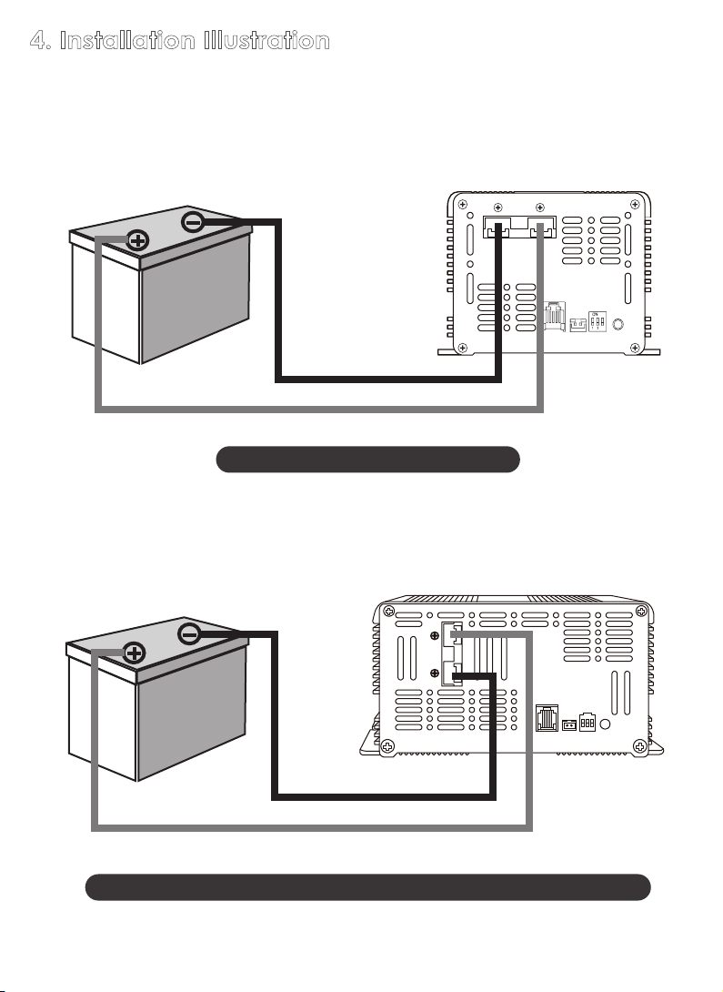
L. Instructions for charging automobile batteries:
- The battery terminal not connected to the chassis has to be connected first.
The other connection is to be made to the chassis, remote from the battery
and fuel line. The battery charger is then to be connected to the supply mains.
- After charging, disconnect the battery charger from the supply mains. Then
remove the chassis connection and then battery connection.

2. Installation Location:
Physical requirements for installation
Condition Description
The unit is intended for use in a dry location. Do not allow water
or other fluids to drip or splash on the charger. Do not mount
the charger in an area subject to rain, spray or splashing bilge
water.
Do not expose the charger to metal filings or any other form
of conductive contamination. The presence of conductive
contamination can cause damage and void your warranty.
For best performance, the ambient air temperature should be
between 5°F (-15°C) and 113°F (45°C)- the cooler the better.
At higher ambient temperatures, the output current will be
automatically reduced to protect the charger from high internal
temperatures.
Dry
Clean
Cool
Ventilated
Allow at least 4 inches (10 cm) of clearance around all sides
of the charger for air flow. Ensure that the ventilation openings
on the unit are not obstructed. If mounting in a compartment,
ventilate the compartment with louvres or cut-outs to prevent
overheating.
Close to AC
junction box
Avoid the use of extended wire lengths if possible.
Close to
batteries
Avoid excessive cable lengths and use the recommended
wire lengths and sizes. Undersized or overly long cables may
affect charging accuracy.
Safe
Working in the vicinity of lead-acid batteries is dangerous.
Batteries generate explosive gases during normal operation.
It is safest not to install electrical equipment in these areas.
4
IMPORTANT
This product is best mounted in a Horizontal position.
If the unit is mounted in a vertical position,
The cooling fan must be at the bottom of the unit.
Maintenance
You should clean the exterior of the unit periodically with a dry
cloth to prevent accumulation of dust and dirt.
At the same time, tighten the screws on the DC input terminals.

3. Overview
A. Product Introduction
Warning: Damage caused by wrong positive (+) and negative (-) connection
is not covered by the warranty.
1
2 3 4
5
1
23 4
5
6
7
8
7
6
Rear viewFront view
Rear viewFront view
5
BC-1215HT / BC-2407HT
BC-1230HT / BC-2415HT
99
9 9
8

6
1. DC OUTPUT :
Check +/- before installation
2. Remote control-LCD
( Note 2)
Battery Temp. Sensor
Warning!
1.
Connectto the battery Negative (-)
terminal only.
2.Positive (+) terminal may damage
Sensor & Charger.
3. Battery Temp. Sensor
4.
Charging Mode Selection
(Please refer to page 9)
5. Charging Status
6. Main Switch
7. Fan
8. AC Input
1
23
45
7
8
6
Rear viewFront view
Note 1:
The slave switch of the remote control just cuts out the output. If you want to turn off the
charger completely, please switch off main switch of charger body.
Battery Temp. Sensor: To detect the battery temp. While charging, please connect the
wire sensor to the battery Negative (-) terminal.
DON'T connect the sensor to the battery Positive (+) terminal. It may
damage
the sensor & charger.
Warning: Damage caused by wrong sensor cable connection is not
covered by the warranty.
When the battery (-) pole temp. reaches 65°C (+/-5°C) / 149°F (+/-41°F), the charger
would stop output.
9. Bracket
Slave Switch
Remote control-LCD
Fault
ON / OFF
Mode
( Note 1 )
BC-1260HT / BC-2430HT
9 9

bracket - 2 parts : rear and frame.
B. Accessory
FRONT VIEW
Frame
Rear
7
How to instal?
①
With the frame only, if there’s the hole on the wall for phone jack.
C . Isolated Design
The DC battery charging circuits of this charger are galvanically isolated
by a transformer from the AC power circuits. This feature reduces the risk
of electric shock .
②
With the frame and rear both, if the user just can screw the bracket on the
wall,
no hole for phone jack.
or
Note 2:
Mode Selection
Remote
Control
Battery Temp.
Sensor
Charger
State
black (negative)
red (positive)
Battery

8
Mode Selection
Remote
Control
Battery Temp.
Sensor
Charger
State
Battery
black (negative)
red (positive)
Remote
Control
Battery Temp.
Sensor
Charger
State
Mode Selection
3
black (negative)
red (positive)
Battery
BC-1230HT / BC-2415HT / BC-1260HT / BC-2430HT
BC-1215HT / BC-2407HT
4. Installation Illustration
Before charging, read the instructions; for indoor use only.
Disconnect the supply
before making or breaking the connections to the battery.

9
5. Charging mode Selection & Volt Graph (0:OFF )
1 2 3
O N
Mode 2
(003)
standby
LED color
green green
1 2 3
ON
Mode 1
(100)
standby
orange orange
LED color
red green
Battery charger
mode.
power supply
mode.
(DON’T charge the
battery by this mode,
would be over-
charged. NOT cover
by
the warranty.).
(1).
The chargers have been approved as Ignition Protected. They may be installed
in areas containing gasoline tanks and fittings which require Ignition Protected
equipment. It is safest not to install electrical equipment in these areas.
WARNING
Explosive gases; Prevent flames and sparks; Provide adequate ventilation during
charging.
Include a warning against recharging non-rechargeable batteries.
If the supply cord is damaged,
it must be replaced by a special cord or assembly
available from the manufacturer or its service agent.
Explosive gas precautions
(2).
To reduce the risk of battery explosion, follow these instructions and those
published by the battery manufacturer and the manufacturer of the equipment
in which the battery is installed.
(3).
Working in the vicinity of lead-acid batteries is dangerous. Batteries generate
explosive gases during normal operation. Therefore you must read this guide
and
follow the instructions exactly before installing or using your charger.

6. Charger LCD Remote Control :
Fault
ON / OFF
Mode
Fault
ON / OFF
Mode
1. OFF
2. Mode 1: no battery connected.
4. Mode 1: battery full.3. Mode 1: while charging.
5. Mode 2: power supply mode. 6. Over temperature protection.
7. High battery volt protection.
Fault
ON / OFF
Mode
power
supply
DC output
volt
Fault
ON / OFF
Mode
battery
volt
Fault
ON / OFF
Mode
Fault
ON / OFF
Mode
Fault
ON / OFF
Mode
** If overload, the output volt would go down
gradually, according to the load current. **
Graph
ON/OFF
SWITCH
Fault LED
(red lighting)
Fault
ON / OFF
charging current
Battery
Capacity
Display Content :
charging mode
Do not dispose this product as unsorted
municipal waste. Collection of such waste
separately for special treatment is necessary.
This product must not be disposed together
with the domestic waste.
This product has to be disposed at an authorized place
for recycling of electrical and electronic appliances.
By collecting and recycling waste, you help save natural
resources, and make sure the product is disposed in
an environmental friendly and healthy way.
10

11
Model
BC-1215HT BC-2407HT
Voltage range
Frequency range
Efficiency
Power factor
Input socket
Mode Selection
Bulk Stage
Absorption stage
Float stage
Aging (sulfated)
battery
Recommended
battery capacity
Leakage current
from battery
Over temperature
Overload
Output short circuit
Microprocessor
check
WORKING TEMP.
WORKING HUMIDITY
STORAGE TEMP.,
HUMIDITY
TEMP. COEFFICIENT
Remote Control
Dimension
(L x W x H)
Weight
INPUT
OUTPUT
PROTECTION
ENVIRONMENT
OTHER
230Vac (180~240Vac).
50/60Hz
>=85%
0.5 at full load (±5%)
IEC plug
55°C±5°C (131°F±41°F)
YES
YES
YES
-15°C ~ +45°C (5°F ~ 113°F)
20 ~ 90% RH non-condensing
-30°C ~ +70°C (-22°F ~ +158°F) , 10 ~ 95% RH
±0.05%°C (0°C ~ 50°C/32°F ~122°F)
YES
195 x 126 x 82.5mm
2.1kgs
45 ~ 150Ah (12V)
<1mA
Mode 1
14.1V / 15A
14.1V / 15A max.
13.5V / 15A max.
Mode 2 *¹
13.5V / 15A
13.5V / 15A
13.5V / 15A
Mode 1
28.2V / 7A
28.2V / 7A max.
27.0V / 7A max.
Mode 2 *¹
27V / 7A
27V / 7A
27V / 7A
14.1V / 2A
The battery <9V.
28.2V / 1A
The battery <18V.
30 ~ 90Ah (24V)
<1mA
BC-1215HT / BC-2407HT
specification
Note: Specifications subject to change without notice.
*1 Mode 2: DON’T charge the battery!
*2 The above spec. ±0.5V for 12V spec.; ±1.0V for 24V spec.; Amp. ±10% is acceptable.

12
BC-1230HT / BC-2415HT specification
Model
BC-1230HT BC-2415HT
Voltage range
Frequency range
Efficiency
Power factor
Input socket
Mode Selection
Bulk Stage
Absorption stage
Float stage
Aging (sulfated)
battery
Recommended
battery capacity
Leakage current
from battery
Over temperature
Overload
Output short circuit
Microprocessor
check
WORKING TEMP.
WORKING HUMIDITY
STORAGE TEMP.,
HUMIDITY
TEMP. COEFFICIENT
Remote Control
Dimension
(L x W x H)
Weight
INPUT
OUTPUT
PROTECTION
ENVIRONMENT
OTHER
100~240Vac
50/60Hz
>=85%
1.0 at full load (±5%)
IEC plug
55°C±5°C (131°F±41°F)
YES
YES
YES
-15°C ~ +45°C (5°F ~ 113°F)
20 ~ 90% RH non-condensing
-30°C ~ +70°C (-22°F ~ +158°F) , 10 ~ 95% RH
±0.05%°C (0°C ~ 50°C/32°F ~122°F)
YES
235 x 179 x 90mm
3.0kgs
75 ~ 250Ah (12V)
<1mA
Mode 1
14.1V / 30A
14.1V / 30A max.
13.5V / 30A max.
Mode 2
*¹
13.5V / 30A
13.5V / 30A
13.5V / 30A
Mode 1
28.2V / 15A
28.2V / 15A max.
27.0V / 15A max.
Mode 2
*¹
27V / 15A
27V / 15A
27V / 15A
45 ~ 150Ah (24V)
<1mA
14.1V / 4A
The battery <9V. The battery <18V.
28.2V / 2A
Note: Specifications subject to change without notice.
*1 Mode 2: DON’T charge the battery!
*2 The above spec. ±0.5V for 12V spec.; ±1.0V for 24V spec.; Amp. ±10% is acceptable.

13
14.1V / 8A
The battery <9V.
28.2V / 4A
The battery <18V.
BC-1260HT / BC-2430HT
specification
Model
BC-1260HT BC-2430HT
Voltage range
Frequency range
Efficiency
Power factor
Input socket
Mode Selection
Bulk Stage
Absorption stage
Float stage
Aging (sulfated)
battery
Recommended
battery capacity
Leakage current
from battery
Over temperature
Overload
Output short circuit
Microprocessor
check
WORKING TEMP.
WORKING HUMIDITY
STORAGE TEMP.,
HUMIDITY
TEMP. COEFFICIENT
Remote Control
Dimension
(L x W x H)
Weight
INPUT
OUTPUT
PROTECTION
ENVIRONMENT
OTHER
100~240Vac
50/60Hz
>=85%
1.0 at full load (±5%)
IEC plug
55°C±5°C (131°F±41°F)
YES
YES
YES
-15°C ~ +45°C (5°F ~ 113°F)
20 ~ 90% RH non-condensing
-30°C ~ +70°C (-22°F ~ +158°F) , 10 ~ 95% RH
±0.05%°C (0°C ~ 50°C/32°F ~122°F)
YES
328 x 179 x 90mm
4.0kgs
180 ~ 600Ah (12V)
<1mA
Mode 1
14.1V / 60A
14.1V / 60A max.
13.5V / 60A max.
Mode 2 *¹
13.5V / 60A
13.5V / 60A
13.5V / 60A
Mode 1
28.2V / 30A
28.2V / 30A max.
27.0V / 30A max.
Mode 2 *¹
27V / 30A
27V / 30A
27V / 30A
90 ~ 300Ah (24V)
<1mA
Note: Specifications subject to change without notice.
*1 Mode 2: DON’T charge the battery!
*2 The above spec. ±0.5V for 12V spec.; ±1.0V for 24V spec.; Amp. ±10% is acceptable.

7.Charging Formula
( A ) . Charging Time
Formula
Example
Charging time will depend on the capacity of your battery and on how
deeply it is discharged.
The following equation calculates an approximate
charging time.
Charging time =
where:
Charging Time: Battery recharge time in hours
CAP:
Battery capacity in amp-hours
DOD: Battery depth of discharge in per cent. A fully
discharged battery has 100% DOD
CC:
Charge current, the rated current output of the
charger in amperes
80%:
Typical charging efficiency forlead-acid batteries
A Group size battery rated at 100 amp-hours is 40% discharged, that is,
it has a DOD = 40. Charging time with a C-15L-12 unit is
calculated as follows:
Charging time = = 3.3 hours
CC x 80%
15A x 80%
100Ah x 40%
CAP x DOD
( B ) . Discharging Time
To achieve 50% cycling you should calculate your Amp-hour consumption between
charging cycles and use a battery bank with twice that capacity. To calculate Amp hour
consumption, first look at the rating plate on your AC appliance or tools.
Each appliance or tool will be rated in either AC Amps or AC watts or AC VA(Volts-Amps)
apparent power.
Use one of the following to calculate the DC Amp-hour draw for a 12 Volt system:
(AC Amps x 10) x 1.1 x hours of operation = DC Amp-hours
(AC watts/12) x 1.1 x hours of operation = DC Amp-hours
(AC VA/12) x 1.1 x hours of operation = DC Amp-hours
In all formulas, 1.1 is the factor for inverter/charger efficiency.
Calculate the above for every AC appliance or tool you intend to use on your inverter.
This will give you the total number of Amp-hours used between recharges.
Size your battery
bank using this number as a guideline. A good rule to follow is to size the battery bank about
2 times larger than your total Amp-hour load requirement. Plan on recharging when 50% discharged.
Many electric motors have momentary starting requirements well above their operational rating.
Start up watts are listed where appropriate. Individual styles and brands of appliances may vary.
NOTICE: Lead-acid battery is recommended for inverter/charger models, also the LiFePO4 battery.
14
This manual suits for next models
5
Table of contents
Other Voltech Batteries Charger manuals

Voltech
Voltech BC-1240P-1AP User manual

Voltech
Voltech BC-2415P User manual

Voltech
Voltech SBC-2403 User manual

Voltech
Voltech SBC-1205 User manual

Voltech
Voltech BBC-3140 User manual

Voltech
Voltech BC-1230P User manual

Voltech
Voltech BC-1230P User manual

Voltech
Voltech SBC-5925 User manual

Voltech
Voltech BC-1240P-1 User manual