VOLTWORKS VS-3000QBR User manual

MODEL: VS-3000QBR
M. WARRANTY
This product is designed using the most modern digital technology and under very
strict quality control and testing guidelines. If, however, you feel this product is not
performing as it should, please contact us: usvoltworks@gmail.com We will do our
best to resolve your concerns. If the product needs repair or replacement, make sure
to keep your receipt/invoice, as that will need to be sent back along with the package
and prepaid to VOLTWORKS.
The following situations will void warranty:
1. The box is distorted, damaged or changed, and interior parts damaged because of
an exterior hit or drop not reported at time of delivery.
2. Connect the DC power incorrectly reversing the polarity.
3. Dismantled or repaired the unit by an unauthorized person.
4. The unit was damaged by incorrect installation or operating method.
To find out where to buy any of our products, you may also e-mail:
Customer Service Contact: usvoltworks@gmail.com
V0.20.12
Warning: This manual contains important safety and
operating instruction. Please read it carefully before
useing.
If the inverter still doesn't work after trying above measures, there may
be some faults in the circuit. Please return it to the supplier for
maintenance.
L. FAILURE GUIDELINES
No output voltage,
buzzer sounds
continuously
Incorrect output
voltage
Cannot drive the
load
1. Do not use when the battery is charging.
2. Check the rated voltage of the battery
and make sure that it is in the allowable
range of the input voltage.
1. Turn on the power switch.
2. Check the cables and make sure they
are tightly connected.
1. Use a true RMS multimeter to measure,
such as model FLUKE 177/179.
2. Try to maintain the input voltage in the
range of rated power
3. Change the battery of multimeter then
test again.
Reduce the load power, or turn on the
appliance first, then turn on the inverter.
1. The switch is off.
2. The battery lead
isn't connected well
1. RMS Multimeter
measurement error
2. The battery power
of RMS Multimeter
is low.
3. The input voltage
is too high or too low.
1. Load power is too
large, or the actual
power of the
appliance exceeds
nominal power.
2. The starting power
is larger than rated
power (such as
motor).
The internal inverter soft-start circuit will
buffer starting the appliance.
Cut off the load and let it cool naturally for
10 to 30 minutes. Restart it after it resumes
to normal temperature. The load power is
too large, reduce the total load power to the
range of rated power. Avoid blocking the
vent and improve the ventilation condition.
Reduce the ambient temperature.
No output voltage
Low input DC voltage
High input DC
voltage
Overload
Over temperature
Recharge or replace the battery
Reduce the load power.

SPECIFICATIONS
Model
Rated input Voltage
Continuous Power
Peak Power
Input Voltage Range
Over Voltage Shutdown
Low Voltage Shutdown
Low Voltage Alarm
Output Voltage
Frequency
Wave form
Efficiency
Over heat Protection
Over load protection
Short Circuit protection
Display
USB
No load current
Cooling fan
Storage temperature
Size (L W H)
Weight
12VDC
3000W
6000W
9.5~16VDC
16VDC
9.5VDC
9.8VDC
24VDC
3000W
6000W
19~32VDC
32VDC
19VDC
19.6VDC
Operating Temperature
(Automatic Recovery/
Shutdown )
VS-3000QBR
110V~120V AC±10% (Refer to label)
60Hz ±1Hz
Pure Sine Wave
About 90%
°F °F149 8 ±
3000~3300W
yes
LCD
5VDC 0~2.4A 2 MAX 2.4A
32 -113°F °F
14 ~ 113°F °F
15 8 6.7 inch
15.5lbs / 7.03Kgs
2A 1.2A
Thermal controlled cooling fan. It won't work till inverter
case reaches 104°F only.
Remark:Due to the continuous improvement of products, the technical parameters
in this manual are subject to change without prior notice.
1.
A. INSTRUCTION
The VOLTWORKS pure sine power inverter product line is used for back-up power.
The pure sine product line is ideal for sensitive equipment and provides clean power,
which is more efficient for back-up power applications. The power inverter transforms DC
(direct current) electricity into AC (alternating current) power that can be used for running
a wide variety of tools and appliances. This inverter is perfect for providing mobile power
in cars, boats and work trucks. The inverter can also be utilized as a back-up source of
electricity in the event of an electrical failure or for several off-grid applications such as
camping or in your RV.
Please read this instruction manual carefully and make sure your inverter is installed
properly before using.
B. WARNING AND SAFETY
1) Read the manual before connecting this inverter and keep it for future reference.
2) While opening the product package, please check the integrity of the product and
accessories. If there is any problem, please do not use it.
3) While connecting and using for the first time, if there is smoke or explosion sound in
the product, please stop using immediately and disconnect the product from the
battery and electrical appliances. This may be caused by damage during the
transportation or due to moisture during storage in the warehouse before delivery.
Please contact your seller in time.
4) During daily use, if there is smoke or explosion sound in the product, please don’t
worry, this is due to the internal fuse protection of the product . Please do not
disassemble it by yourself. Please stop using the product immediately. Disconnect
the product from the battery and electrical appliances. Contact the seller in time and
only with seller’s agreement a hired professional personnel can disassemble the
product . Otherwise, it may cause electric shock, fire and serious personal injury
5) Do not put the inverter under direct sun light or near a heating source.
6) The case of inverter will get hot during using. Do not allow flammable materials such
as clothing, sleeping bags, carpet or any other flammable materials to touch the
inverter. The heat from the inverter can damage these items.
7) The power inverter is designed to be used with a negative ground electrical system!
Don't use with positive ground electrical systems (the majority of modern
automobiles, RVs, trucks and boats are negative ground).
8) Do not disassemble the unit randomly: it may cause fire or electric shock.
9) This device should only be serviced by a qualified technician. This item does not
have any serviceable parts.
10) Prevent body contact with grounded surfaces such as pipes, radiators, ranges, and
refrigerator enclosures during installation.
11) Do not operate the inverter if under the influence of alcohol or drugs. Read warning
labels on prescriptions to determine if your judgement or reflexes are impaired while
taking drugs. If there is any doubt, do not operate the inverter.
12) People with pacemakers should consult their physician(s) before using this product.
Electromagnetic fields in close proximity to a pacemaker could cause interference to
or failure of the pacemaker.
13) Keep the inverter well-ventilated. Do not place any objects on top of or next to the
inverter or allow anything to cover the cooling fans; inverter will bel overheating,
causing a potential fire hazard and/or damage to the inverter. Leave adequate
ventilation space underneath the inverter as well; thick carpets or rugs can obstruct
air flow, causing the inverter to overheat.
14) Avoid unintentional starting. Be sure the switch is in the OFF position when not in use
and before plugging in any appliance.
If the inverter still doesn't work after trying above measures, there may
be some faults in the circuit. Please return it to the supplier for
maintenance.
L. FAILURE GUIDELINES
No output voltage,
buzzer sounds
continuously
Incorrect output
voltage
Cannot drive the
load
1. Do not use when the battery is charging.
2. Check the rated voltage of the battery
and make sure that it is in the allowable
range of the input voltage.
1. Turn on the power switch.
2. Check the cables and make sure they
are tightly connected.
1. Use a true RMS multimeter to measure,
such as model FLUKE 177/179.
2. Try to maintain the input voltage in the
range of rated power
3. Change the battery of multimeter then
test again.
Reduce the load power, or turn on the
appliance first, then turn on the inverter.
1. The switch is off.
2. The battery lead
isn't connected well
1. RMS Multimeter
measurement error
2. The battery power
of RMS Multimeter
is low.
3. The input voltage
is too high or too low.
1. Load power is too
large, or the actual
power of the
appliance exceeds
nominal power.
2. The starting power
is larger than rated
power (such as
motor).
The internal inverter soft-start circuit will
buffer starting the appliance.
Cut off the load and let it cool naturally for
10 to 30 minutes. Restart it after it resumes
to normal temperature. The load power is
too large, reduce the total load power to the
range of rated power. Avoid blocking the
vent and improve the ventilation condition.
Reduce the ambient temperature.
No output voltage
Low input DC voltage
High input DC
voltage
Overload
Over temperature
Recharge or replace the battery
Reduce the load power.

2. 3.
C. PARTS LIST
Thermal control cooling fan
DC input connector (+)
DC input connector (-)
1. DC Input Side
Grounding
Inverter power switch
Power Indicator Fault indicator
Remote controller interface
Dual USB ports
AC outlets
AC hard wire terminals
LCD display
2. AC Output side
3. Assemble the remote control box
Switc h
Powe r indicato r
Faul t indicato r
Wir e of remot e
Battery level
status
D. INVERTER INSTALLATION
Ensure there is enough space for the installation, and the location should be meet the
following requirements:
1. Water should not access the inverter.
2. The ambient temperature should be 32~104°F, and the preferred temperature is 50-
77°F. The lower the better in this range of ambient temperature.
3. Do not mount the inverter upside down.
4. Allow 12 inches of space around the inverter to prevent objects from blocking the vents
and to provide enough air to circulate.
5. Do not install the inverter in an environment with high dust, saw dust residue or other
particles that may get sucked into the inverter increasing internal temperature.
6. There will be some electrical arcing or spark when the inverter connects with the
battery. Combustible materials such as gasoline, alcohol, etc. should not be around the
inverter.
7. We recommend mounting the inverter on something stable to prevent it from bouncing.
Impact shock could result in damage to your unit. Be sure to use all four mounting
screws for optimal stability. Mount in a location that can support the weight of the
inverter.
15) Keep inverter away from children. Don't install the inverter where it is accessible to
children.
16) The power inverter will output the same AC power as utility power, please treat the AC
outlets as carefully as you would your home AC outlets. Do not put anything other
than an electrical appliance into the output terminal. It may cause shock or fire.
17) This product cannot be used for medical and life support equipment.
If the inverter still doesn't work after trying above measures, there may
be some faults in the circuit. Please return it to the supplier for
maintenance.
L. FAILURE GUIDELINES
No output voltage,
buzzer sounds
continuously
Incorrect output
voltage
Cannot drive the
load
1. Do not use when the battery is charging.
2. Check the rated voltage of the battery
and make sure that it is in the allowable
range of the input voltage.
1. Turn on the power switch.
2. Check the cables and make sure they
are tightly connected.
1. Use a true RMS multimeter to measure,
such as model FLUKE 177/179.
2. Try to maintain the input voltage in the
range of rated power
3. Change the battery of multimeter then
test again.
Reduce the load power, or turn on the
appliance first, then turn on the inverter.
1. The switch is off.
2. The battery lead
isn't connected well
1. RMS Multimeter
measurement error
2. The battery power
of RMS Multimeter
is low.
3. The input voltage
is too high or too low.
1. Load power is too
large, or the actual
power of the
appliance exceeds
nominal power.
2. The starting power
is larger than rated
power (such as
motor).
The internal inverter soft-start circuit will
buffer starting the appliance.
Cut off the load and let it cool naturally for
10 to 30 minutes. Restart it after it resumes
to normal temperature. The load power is
too large, reduce the total load power to the
range of rated power. Avoid blocking the
vent and improve the ventilation condition.
Reduce the ambient temperature.
No output voltage
Low input DC voltage
High input DC
voltage
Overload
Over temperature
Recharge or replace the battery
Reduce the load power.

4. 5.
Battery Status
FAULT
POWER
ON/OFF
85mm
4.5mm
E. REMOTE CONTROLLER INSTALLATION
1) Fix the remote box on flat surface where a hole should be made, and use 2 screws to fix
it through the two mounting holes on the remote controller.
2) Or fix the remote on a standard 86X86mm(3.39x3.39 inch) power socket;
3) Connect the inverter and remote controller by wire before mounting.
Remark: Without remote controller, you can turn on the inverter by the switch on the
inverter too.
F. BATTERY
1. The battery is designed to supply the inverter with DC input voltage and the rated
voltage should be in accordance with the rated input voltage of the inverter. Any voltage
exceeding the range of the input voltage of the inverter will cause the inverter to go into
overload and could possibly damage the inverter. The battery should supply enough
current for the load. The load is the amp or watt rating of the equipment being powered
by the inverter. A small capacity battery cannot provide enough power for a large
electrical equipment. In this case, the battery will cause the inverter to go into under
voltage protection because of the load put on the battery. A simple way to calculate the
load or amps required from your battery is to divide watts of equipment by battery
voltage.
Due to the consumption of the inverter itself, the actual current will be about 10%. For
example, the voltage of lead acid battery is 12VDC, and load of the equipment is
1000W, therefore, the actual current needed from the battery is about 1000W / 12V =
83.3 amps per hour. Add 10% for efficiency loss and you get 83.3 * 1.10% = 91.6 amp
per hour needed. If you don't know the wattage of your equipment, you can figure the
wattage by multiplying AC amps by AC voltage. For example, a refrigerator is 8 AC
amps * 120 Volts AC = 960 watts. Remember, all equipment has a start-up requirement
3-5x its running wattage. In this example, 960 watts * 3 = 2880 watts needed from the
inverter so don't size your inverter too small.
2. Battery operating time depends on battery capacity and load. The formula for operating
time is: battery capacity divided by the value of the load divided by battery voltage
times 1.10%. For example, using the numbers from above, the battery specification is
12V, 200Ah capacity and the load is 1000W. Take battery capacity 200Ah / 91.6 amps =
2.18 hours of run time if you fully deplete the battery. This is NOT recommended. Deep
cycle batteries last longer when they are only depleted to 50% of capacity.
G. CONNECTION
1. Grounding
The power inverter has a terminal on the rear panel marked " Grounding "or " ". This
is used to connect the chassis of the power inverter to ground. The ground terminal has
already been connected to the ground wire of the AC output receptacle through the
inverter.
The ground terminal must be connected to the ground wire, which will vary depending
on where the power inverter is installed. In a vehicle, connect the ground terminal to the
chassis of the vehicle. In a boat, connect it to the boat's ground system. In a fixed
location, connect the ground terminal to earth.
2
The ground wire must be 14AWG(2.08mm )or larger,and make sure the connections
are well.
2. Battery Connection:
Before you connect the battery cables, make sure the power switch is in the off
position. Connect Red (+) battery cable to Red (+) inverter terminal. Connect Black (-)
battery cable to Black (-) inverter terminal. Connect Red (+) battery cable to Red (+)
battery terminal. Connect Black (-) battery cable to Black (-) battery terminal. Alligator
clamp cables may be used but only to connect to the battery. Do not use clamps on
inverter terminals. Alligator clamps are not a permanent solution. You may see a spark
during connection. Do not reverse the polarity. This may damage the inverter and
void warranty.
Notice:
1) Please do all the safety precautions before connecting, and then check whether the
battery voltage comply with the input voltage of the inverter.
2) The cables must be big enough to bear current, or else the inverter can not power up
a big load because of voltage reduce caused by the small cross-sectional wire.
Refer to the below table to choose cables accordingly.
Inverter Input
voltage Rating power Max current
of cable
Specification of wire
length≤1m
12V
24V
1000W
1500W
2000W
2500W
3000W
4000W
5000W
1000W
1500W
2000W
2500W
3000W
4000W
5000W
100A
150A
200A
250A
300A
400A
500A
50A
75A
100A
125A
150A
200A
250A
2
6AWG(13.30mm )
2
4AWG(21.15mm )
2
3AWG(26.67mm )
2
2AWG(33.62mm )
2
1AWG(42.41mm )
2
0AWG(53.49mm )
2
00AWG(67.43mm )
2
9AWG(6.63mm )
2
7AWG(10.55mm )
2
6AWG(13.3 mm )
2
5AWG(16.77mm )
2
4AWG (21.15mm )
2
3AWG (26.67mm )
2
2AWG (33.62mm )
2
N 13.30mm×
2
N 21.15mm×
2
N 26.67mm×
2
N 33.62mm×
2
N 42.41mm×
2
N 53.49mm×
2
N 67.43mm×
2
N 6.63mm×
2
N 10.55mm×
2
N 13.30mm×
2
N 16.77mm×
2
N 21.15mm×
2
N 26.67mm×
2
N 33.62mm×
Specification of wire
length≤1m
Specification of wire
length≤N m
2
3AWG(26.67mm )
2
1AWG(42.41mm )
2
0AWG(53.49mm )
2
00AWG(67.43mm )
2
2×1AWG(84.82mm )
2
2×0AWG(107mm )
2
2×00AWG(135mm )
2
6AWG(13.3mm )
2
4AWG(21.15mm )
2
3AWG(26.67mm )
2
2AWG(33.62mm )
2
1AWG(42.41mm )
2
0AWG(53.49mm )
2
00AWG(67.43mm )
If the inverter still doesn't work after trying above measures, there may
be some faults in the circuit. Please return it to the supplier for
maintenance.
L. FAILURE GUIDELINES
No output voltage,
buzzer sounds
continuously
Incorrect output
voltage
Cannot drive the
load
1. Do not use when the battery is charging.
2. Check the rated voltage of the battery
and make sure that it is in the allowable
range of the input voltage.
1. Turn on the power switch.
2. Check the cables and make sure they
are tightly connected.
1. Use a true RMS multimeter to measure,
such as model FLUKE 177/179.
2. Try to maintain the input voltage in the
range of rated power
3. Change the battery of multimeter then
test again.
Reduce the load power, or turn on the
appliance first, then turn on the inverter.
1. The switch is off.
2. The battery lead
isn't connected well
1. RMS Multimeter
measurement error
2. The battery power
of RMS Multimeter
is low.
3. The input voltage
is too high or too low.
1. Load power is too
large, or the actual
power of the
appliance exceeds
nominal power.
2. The starting power
is larger than rated
power (such as
motor).
The internal inverter soft-start circuit will
buffer starting the appliance.
Cut off the load and let it cool naturally for
10 to 30 minutes. Restart it after it resumes
to normal temperature. The load power is
too large, reduce the total load power to the
range of rated power. Avoid blocking the
vent and improve the ventilation condition.
Reduce the ambient temperature.
No output voltage
Low input DC voltage
High input DC
voltage
Overload
Over temperature
Recharge or replace the battery
Reduce the load power.

6.
Notice:
1. The above table is only for your reference. In practice, the thick wire can be replaced by
two thin parallel wires if only the total section acreage of the wire meets the
requirements.
2. In high current, the input DC wire may produce voltage drop, therefore, the operating
voltage should be subject to the value on the terminals. If the voltage drop is too large,
it can increase the acreage of the section or reduce the length of the lead. The
recommended length of lead is less than 1m.
3. Connect cathode wire of the battery to the cathode terminal (black) on the back panel of
inverter and then connect the anode wire of the battery to the anode terminal (red) on
the inverter, and fix them.
Warnings:
1) Please wear eye patch and work clothes when working around the battery to avoid the
acid and corrosive objects harm your eyes and skin.
2) Prepare enough water and soap. In case the acid materials contact eyes or skin, clean
it by soap and water as soon as possible. If the acid materials spay to your eyes
accidentally, clean it by cold water immediately and then sent to hospital.
3) Do not put any combustible material in the location of installation for spark will result
when it is connected to the battery.
4) Keep good ventilation. The battery may produce a little inflammable gas when it works,
so keep away from the inverter and it is better to install them in different space.
5) Fix the connecting wire of the input DC, or it will result the over-reduction of the voltage
or over-temperature of the wire.
6) Reverse connection of the polarities or the short circuit will burn the fuse or result the
permanence damage of the internal elements of inverter.
7) Take away the metal accouterment, such as ring or watch, when installation to avoid
the short circuit.
8) Although there is over-voltage protection, it may also cause damage of the inverter if
the input voltage is too high.
3. Connection of the AC appliance
Put the power plug of the AC appliance load into the output AC receptacle ofthe
inverter directly.
Warnings:
1. Make sure that the switches of the inverter and appliance power are in OFF position
before connection.
2. Check the power cord. If it is damaged, it should be connected after replacement.
3. Each outlet of the inverter has a given current rating of the manufacturer. It shall not
exceed this value during use. Otherwise, the socket may be damaged by overheating
and may cause an electric shock. The maximum output power of a single socket is
shown in the following table:
Output socket AC output voltage Single socket
max output current
Single socket
max output power
110~120VAC
220~240VAC
220~240VAC
220~240VAC
15A
16A
13A
10A
1500W
3000W
2500W
2000W
220~240VAC 13A 2500W
Connection of big load
For the appliances with a load more than the limit of AC socket ,please connect to the
Hard wire Terminals(if have) ,make sure the ground terminal of inverter connected with
ground terminal of appliance.
H. SOFT START TECHNOLOGY
The soft start technology built into this inverter protects the unit from delivering too
much AC power at once by gradually increasing the AC voltage pushed out. To make
sure that you are utilizing this feature, turn on the appliance being used before turning
on the inverter. This is especially necessary for equipment that has an inductive load or
electrical motor.
I. OUTPUT VOLTAGE & WAVEFORM
The electrical waveform output of this inverter is a pure sine wave, which has the same
quality as utility and/or domestic power This type of waveform is suitable for most .
electrical devices, appliances and tools. This pure sine wave unit provides more
capabilities than modified sine wave inverters because it is a cleaner form of power.
The pure sine wave also effectively reduces the noise produced while using
appliances.
J. LCD DISPLAY
While inverter is working, the LCD display will show Battery Status Level,Pure Sine
Wave Symbol, Input Voltage , Output Voltage, current etc . Once the inverter is on
protection mode, the following codes will shown:
7.
162.6 Volta peak
Pure Sine Wave Output
(120 VAC Model)
If the inverter still doesn't work after trying above measures, there may
be some faults in the circuit. Please return it to the supplier for
maintenance.
L. FAILURE GUIDELINES
No output voltage,
buzzer sounds
continuously
Incorrect output
voltage
Cannot drive the
load
1. Do not use when the battery is charging.
2. Check the rated voltage of the battery
and make sure that it is in the allowable
range of the input voltage.
1. Turn on the power switch.
2. Check the cables and make sure they
are tightly connected.
1. Use a true RMS multimeter to measure,
such as model FLUKE 177/179.
2. Try to maintain the input voltage in the
range of rated power
3. Change the battery of multimeter then
test again.
Reduce the load power, or turn on the
appliance first, then turn on the inverter.
1. The switch is off.
2. The battery lead
isn't connected well
1. RMS Multimeter
measurement error
2. The battery power
of RMS Multimeter
is low.
3. The input voltage
is too high or too low.
1. Load power is too
large, or the actual
power of the
appliance exceeds
nominal power.
2. The starting power
is larger than rated
power (such as
motor).
The internal inverter soft-start circuit will
buffer starting the appliance.
Cut off the load and let it cool naturally for
10 to 30 minutes. Restart it after it resumes
to normal temperature. The load power is
too large, reduce the total load power to the
range of rated power. Avoid blocking the
vent and improve the ventilation condition.
Reduce the ambient temperature.
No output voltage
Low input DC voltage
High input DC
voltage
Overload
Over temperature
Recharge or replace the battery
Reduce the load power.

8. 9.
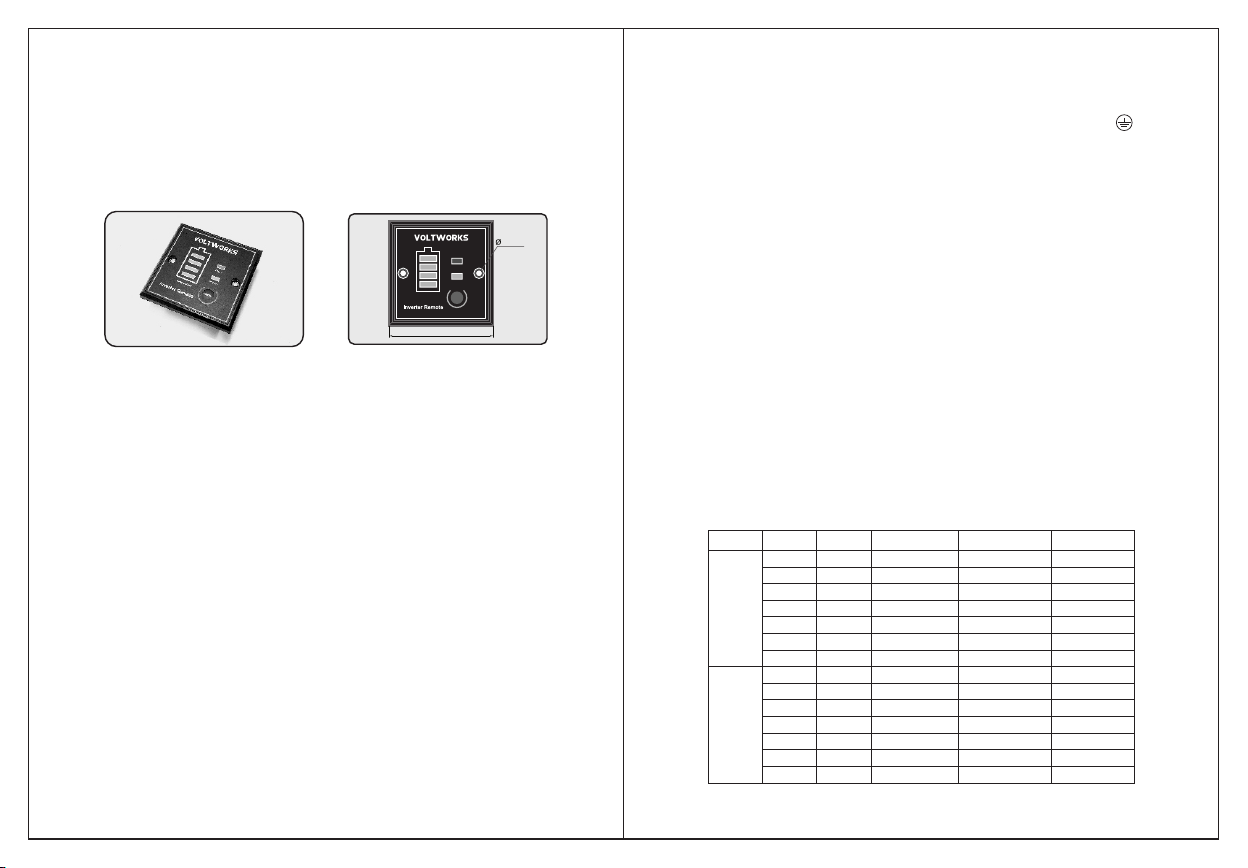
1.LO: Low voltage protection
2. HI: High voltage protection
3. OL: Overload or short-circuit protection
4. OH: overheat protection.
K. PROTECTIONS IN THE INVERTER
1. Input under-voltage alarm: When the input DC voltage is lower than 9.8V (19.6V), the
buzzer will whistle intermittently to remind that the inverter will go into the under
voltage protection.
2. Under voltage protection: The inverter will automatically shut down when the input DC
voltage is lower than 9.5V(19V). The buzzer will whistle continuously and the green
light is off, red light is on. Please turn off the inverter and use it after recharging the
battery.
3. Over voltage protection: The inverter will automatically shut down when the input DC
voltage is higher than 16V(32V). The buzzer will whistle continuously and the green
light is off, red light is on. Please turn off the inverter and adjust the input voltage to the
admissible range.
4. Overload protection: The inverter will automatically shut down when the load is higher
than the rated power. The buzzer will whistle continuously. Turn off the inverter and
resume to normal operation after taking away the excessive load.
5. Short-circuit protection: The AC output will be automatically shut down when short
circuited. It will automatically reset after the problem is solved.
6. Thermal protection: The unit will get hot during operation. If the temperature is higher
than 149°F, the inverter will automatically shut down. Then the buzzer will whistle
continuously and the green light is off, red light is on. Please turn off the inverter, and
continue using it after the temperature goes back to normal naturally. Meanwhile find
out the factors causing the fault, such as ventilation, ambient temperature, vent, load
power etc. It can avoid similar things from happening again.
NOTE: The numbers in the parenthesis are for 24V models. In the case of over
voltage, under voltage and thermal protection, the inverter will shut down. When
the inverter is in the OFF position, the inverter doesn't consume battery current.
L. QUICK KNOWLEDGE ABOUT INVERTER
! Ensure Your Battery Size Is Big Enough And Voltage Is Correct.
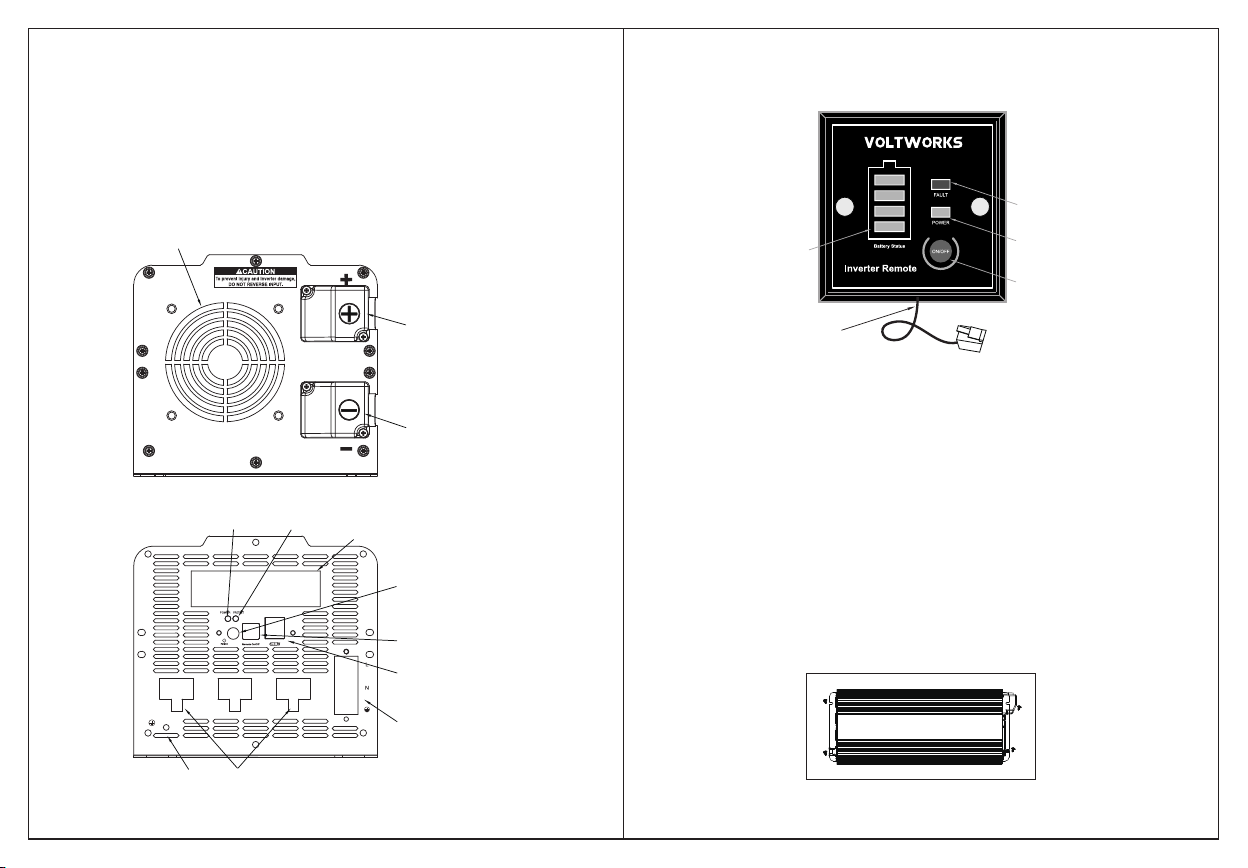
A. CORRECTLY CONNECTING THE INVERTER FOR FIRST USE.
1) Secure the provided Negative (black) DC cable connect to the Negative (-) bolt on the
inverter, and the other end to the Negative (-) post on the battery.
2) Secure the provided Positive (Red) DC cable to the Positive (+) bolt on the inverter, and
the other end to the Positive (+) post on the battery.
3) The nuts of the connection posts must be tightened to ensure well connected.
4) Press the power switch for one second, because it is a long press type switch.
120
WARNING: REVERSE CONNECTED THE CABLES WILL DAMAGE THE INVERTER
AND AVOID YOUR WARRANTY!
● Reduce the load power, or turn on the
appliance first, then turn on the inverter.
● Choose a bigger inverter
● Change a bigger battery and ensure fully
charged.
No output voltage,
buzzer whistles
continuously
Problem Reason Solutions
Low Input DC Voltage
High Input DC Voltage
Overload
Over temperature
● Do not use it when the battery is charging
● Check the rated voltage of the battery and
make sure that it is in the allowable range
ofthe input voltage.
Reduce the load power
● Cut off the load and let it cool naturally for
10 to 30 minutes.
● Restart it after it resumes to normal
temperature. Reduce the load. avoid
blocking the vent and improve the
ventilation condition.
No AC outputvoltage? 1.The power switch is off.
2.Poor contact with battery.
● Press the power switch for 1-2 second to
turn it on. it is a long press type switch
●Check the cables and make sure they are
tightly connected.
Output voltagebelow
100 V AC?
“True RMS”voltage meter is
required to properly measure
outputvoltage of modified
wave inverter
Cannot drive theload?
Tester indicated
"Open Ground"?
This is because it is not connected
to a"true Earth ground ", meaning
it is not connected to a metal rod
stuck in theEarth. it would be
impossible to do so in a boat or car
while moving. The powerinverter
DOES NOT and cannot create a
true Earth ground on its own.
● Test output voltage with a True RMS meter
● Try to maintain the input voltage in the
range of rated power
● Change the battery of the meter then test
again.
1.Load power is too large. Or the
actualpower of the appliance
exceedsnominal power.
2.The starting power is larger than
ratedpower (especially for
appliances withmotor)
3.Battery is too small.
● Don't need the tester to do the Grounding
Test.
● Refer to the manual to do the Grounding
Starting alarm ?
The main reason is that ths
instantaneous current is too large,
which leads to the detection of low
voltage and trigger under-voltage
alarm.
Please restart the inverter several
times.
Got 40V or so while
testing inverter's
ground wire and
zero line?
This voltage has no meaning,
zero line can be ground.
This is normal, there is no current
leakage.
Low Input DC Voltage
If the unit still doesn't work normally after using all the methods above, it maybe the
internal faults of the circuit. Please contact us: usvoltworks@gmail.com
B. TROUBLESHOOTING TIPS
If the inverter still doesn't work after trying above measures, there may
be some faults in the circuit. Please return it to the supplier for
maintenance.
L. FAILURE GUIDELINES
No output voltage,
buzzer sounds
continuously
Incorrect output
voltage
Cannot drive the
load
1. Do not use when the battery is charging.
2. Check the rated voltage of the battery
and make sure that it is in the allowable
range of the input voltage.
1. Turn on the power switch.
2. Check the cables and make sure they
are tightly connected.
1. Use a true RMS multimeter to measure,
such as model FLUKE 177/179.
2. Try to maintain the input voltage in the
range of rated power
3. Change the battery of multimeter then
test again.
Reduce the load power, or turn on the
appliance first, then turn on the inverter.
1. The switch is off.
2. The battery lead
isn't connected well
1. RMS Multimeter
measurement error
2. The battery power
of RMS Multimeter
is low.
3. The input voltage
is too high or too low.
1. Load power is too
large, or the actual
power of the
appliance exceeds
nominal power.
2. The starting power
is larger than rated
power (such as
motor).
The internal inverter soft-start circuit will
buffer starting the appliance.
Cut off the load and let it cool naturally for
10 to 30 minutes. Restart it after it resumes
to normal temperature. The load power is
too large, reduce the total load power to the
range of rated power. Avoid blocking the
vent and improve the ventilation condition.
Reduce the ambient temperature.
No output voltage
Low input DC voltage
High input DC
voltage
Overload
Over temperature
Recharge or replace the battery
Reduce the load power.
Table of contents
Other VOLTWORKS Inverter manuals
Popular Inverter manuals by other brands

Tektronix
Tektronix MTG300 Specifications

Morningstar
Morningstar SureSine 150 W Installation and operation manual

TLS
TLS Omnia.9sg Preliminary manual

Kostal
Kostal PIKO 36 EPC operating manual

Gude
Gude GC 130 WIG Translation of original operating instructions

Unipower
Unipower Scimitar 3000 Series Installation & operating manual

SolarEdge
SolarEdge Solar Inverter installation guide

National Instruments
National Instruments NI 5421 s Specifications

Drivecon
Drivecon VF61 Function manual

Generac Power Systems
Generac Power Systems Guardian 005324-1 owner's manual

Steren
Steren LAM-605 instruction manual

Mitsubishi Electric
Mitsubishi Electric FR-E8AXY E KIT instruction manual