Volvo 39834476 User manual

Instruction No
Version
Part. No.
31408665
1.0
39834476, 39825250, 39841562, 39825249, 39825248, 39825247, 39825237, 39825238, 39825233, 39829613
Multimedia system, RSE, two screens, with two players
Instruction No
Version
Part. No.
31408665
1.0
39834476, 39825250, 39841562, 39825249, 39825248, 39825247, 39825237, 39825238, 39825233, 39829613
Multimedia system, RSE, two screens, with two players
Installation instructions, accessories
Volvo Car Corporation Gothenburg, Sweden
©
Volvo Car Corporation
Multimedia system, RSE, two screens, with two players
-
31408665
-
V1.0
Page 1 / 44

Materials
Designation
Part number
Cable tie, 750 mm
988734
Electrical tape
Equipment
IMG-
345497
IMG-
239664
IMG-
382160
Installation instructions, accessories
Volvo Car Corporation Gothenburg, Sweden
©
Volvo Car Corporation
Multimedia system, RSE, two screens, with two players
-
31408665
-
V1.0
Page 2 / 44

IMG-
382285
Installation instructions, accessories
Volvo Car Corporation Gothenburg, Sweden
©
Volvo Car Corporation
Multimedia system, RSE, two screens, with two players
-
31408665
-
V1.0
Page 3 / 44

Information
1
Read through all of the instructions before starting installation.
Notifications and warning texts are for your safety and to
minimise the risk of something breaking during installation.
Ensure that all tools stated in the instructions are available before
starting installation.
Certain steps in the instructions are only presented in the form of
images. Explanatory text is also given for more complicated
steps.
In the event of any problems with the instructions or the
accessory, contact your local Volvo dealer.
Color symbols
2
IMG-
363036
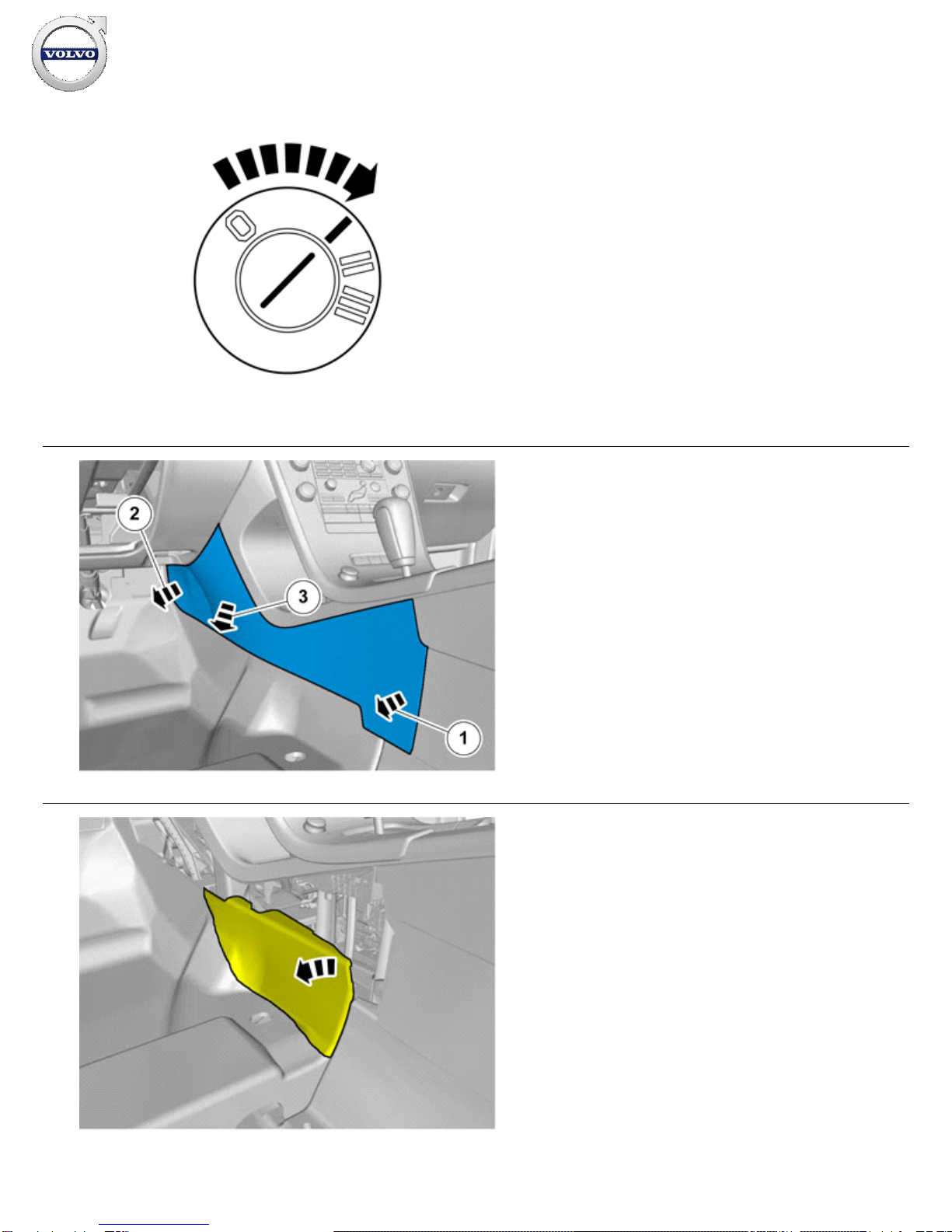
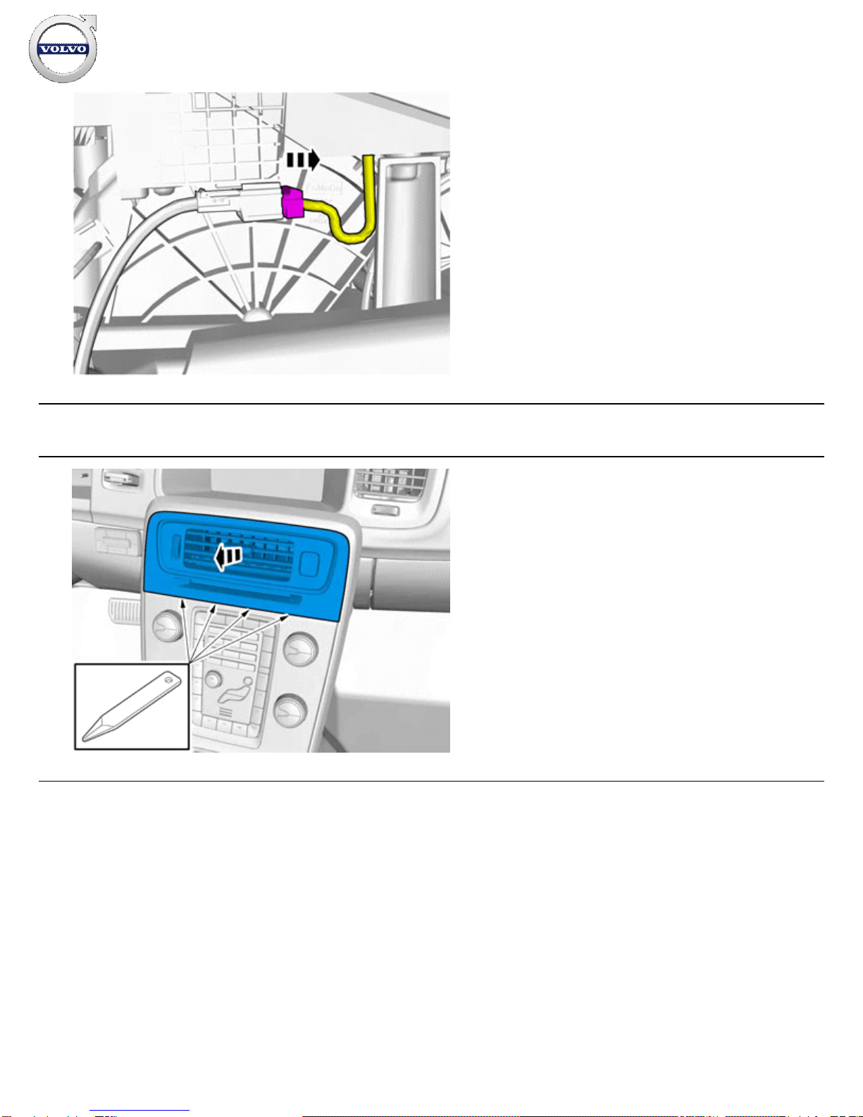
1. Used for focused component, the component with which you
will do something.
2. Used as extra colors when you need to show or differentiate
additional parts.
3. Used for attachments that are to be removed/installed. May be
screws, clips, connectors, etc.
4. Used when the component is not fully removed from the
vehicle but only hung to the side.
5. Used for standard tools and special tools.
6. Used as background color for vehicle components.
Note!
This colour chart displays (in colour print and electronic
version) the importance of the different colours used in the
images of the method steps.
Removal
Installation instructions, accessories
Volvo Car Corporation Gothenburg, Sweden
©
Volvo Car Corporation
Multimedia system, RSE, two screens, with two players
-
31408665
-
V1.0
Page 4 / 44

3
IMG-
332194
Set the ignition key to position I.
4
IMG-
292804
Remove the panel.
5
IMG-
292806
Fold the carpet to the side.
Installation instructions, accessories
Volvo Car Corporation Gothenburg, Sweden
©
Volvo Car Corporation
Multimedia system, RSE, two screens, with two players
-
31408665
-
V1.0
Page 5 / 44

6
IMG-
292823
1. Unhook the cable harness clips.
2. Disconnect the connector.
7
IMG-
292826
Remove the panel.
Vehicles with the 4C system.
Installation instructions, accessories
Volvo Car Corporation Gothenburg, Sweden
©
Volvo Car Corporation
Multimedia system, RSE, two screens, with two players
-
31408665
-
V1.0
Page 6 / 44

8
IMG-
292827
Disconnect the connector.
All vehicles
9
IMG-
346236
Remove the panel.
Installation instructions, accessories
Volvo Car Corporation Gothenburg, Sweden
©
Volvo Car Corporation
Multimedia system, RSE, two screens, with two players
-
31408665
-
V1.0
Page 7 / 44

10
IMG-
340984
Disconnect the connector.
11
IMG-
340985
Remove the screws.
12
IMG-
355818
Remove the screws.
Installation instructions, accessories
Volvo Car Corporation Gothenburg, Sweden
©
Volvo Car Corporation
Multimedia system, RSE, two screens, with two players
-
31408665
-
V1.0
Page 8 / 44

Cars with automatic transmissions
13
IMG-
293006
14
IMG-
293007
Release the shift-lock function.
All vehicles
Installation instructions, accessories
Volvo Car Corporation Gothenburg, Sweden
©
Volvo Car Corporation
Multimedia system, RSE, two screens, with two players
-
31408665
-
V1.0
Page 9 / 44

15
IMG-
340981
Remove the panel.
Cars with manual transmissions
16
IMG-
345292
All vehicles
Installation instructions, accessories
Volvo Car Corporation Gothenburg, Sweden
©
Volvo Car Corporation
Multimedia system, RSE, two screens, with two players
-
31408665
-
V1.0
Page 10 / 44

17
IMG-
293021
18
IMG-
293022
19
IMG-
293023
Remove the screws.
Installation instructions, accessories
Volvo Car Corporation Gothenburg, Sweden
©
Volvo Car Corporation
Multimedia system, RSE, two screens, with two players
-
31408665
-
V1.0
Page 11 / 44

20
IMG-
377998
Remove the screws.
21
IMG-
372558
Adjust to the lowermost position.
Repeat on the other side.
22
IMG-
372559
Adjust the seat to center position so that the seat fastening bolts
can be removed.
Repeat on the other side.
Installation instructions, accessories
Volvo Car Corporation Gothenburg, Sweden
©
Volvo Car Corporation
Multimedia system, RSE, two screens, with two players
-
31408665
-
V1.0
Page 12 / 44

23
IMG-
332179
1.
Set the ignition key to position 0.
2. Remove the battery's negative cable.
24
IMG-
329148
Installation instructions, accessories
Volvo Car Corporation Gothenburg, Sweden
©
Volvo Car Corporation
Multimedia system, RSE, two screens, with two players
-
31408665
-
V1.0
Page 13 / 44

25
IMG-
340979
26
IMG-
340980
Remove the screws.
Tightening torque: ,
27
IMG-
303005
Installation instructions, accessories
Volvo Car Corporation Gothenburg, Sweden
©
Volvo Car Corporation
Multimedia system, RSE, two screens, with two players
-
31408665
-
V1.0
Page 14 / 44

28
IMG-
303006
Remove the screws.
Tightening torque: ,
Alternative 1
29
IMG-
380657
Alternative 2
Installation instructions, accessories
Volvo Car Corporation Gothenburg, Sweden
©
Volvo Car Corporation
Multimedia system, RSE, two screens, with two players
-
31408665
-
V1.0
Page 15 / 44

30
IMG-
380655
31
IMG-
380656
All vehicles
Installation instructions, accessories
Volvo Car Corporation Gothenburg, Sweden
©
Volvo Car Corporation
Multimedia system, RSE, two screens, with two players
-
31408665
-
V1.0
Page 16 / 44

32
IMG-
329151
33
IMG-
373198
Note!
Orientation view
34
IMG-
329209
Remove the screws.
Disconnect the connector.
Installation instructions, accessories
Volvo Car Corporation Gothenburg, Sweden
©
Volvo Car Corporation
Multimedia system, RSE, two screens, with two players
-
31408665
-
V1.0
Page 17 / 44

35
IMG-
382639
Disconnect the connector, if applicable.
36
IMG-
329153
Caution!
Be extra careful when removing or installing this component.
37
IMG-
377070
Repeat the steps when removing on opposite side.
Installation instructions, accessories
Volvo Car Corporation Gothenburg, Sweden
©
Volvo Car Corporation
Multimedia system, RSE, two screens, with two players
-
31408665
-
V1.0
Page 18 / 44

Accessory installation
38
IMG-
382637
Use:
988734, Cable tie, 750 mm
39
IMG-
382638
Use:
988734, Cable tie, 750 mm
Installation instructions, accessories
Volvo Car Corporation Gothenburg, Sweden
©
Volvo Car Corporation
Multimedia system, RSE, two screens, with two players
-
31408665
-
V1.0
Page 19 / 44

40
IMG-
372824
Use:
, Electrical tape
41
IMG-
373154
Thread the cable tie from the head restraint's inner mounting.
Route the cable tie inside the backrest between the upholstery's
thin foam and the impact protection.
42
IMG-
380827
Place the component where indicated in the graphic.
Installation instructions, accessories
Volvo Car Corporation Gothenburg, Sweden
©
Volvo Car Corporation
Multimedia system, RSE, two screens, with two players
-
31408665
-
V1.0
Page 20 / 44
This manual suits for next models
9
Table of contents
Other Volvo Car Video System manuals

Volvo
Volvo SENSUS User manual

Volvo
Volvo 30756177 User manual

Volvo
Volvo 31399495 User manual

Volvo
Volvo SENSUS User manual

Volvo
Volvo SENSUS User manual

Volvo
Volvo 39825257 User manual

Volvo
Volvo Sensus Seven User manual

Volvo
Volvo On Call with Sensus Connect User manual

Volvo
Volvo 39825257 User manual

Volvo
Volvo SENSUS INFOTAINMENT User manual