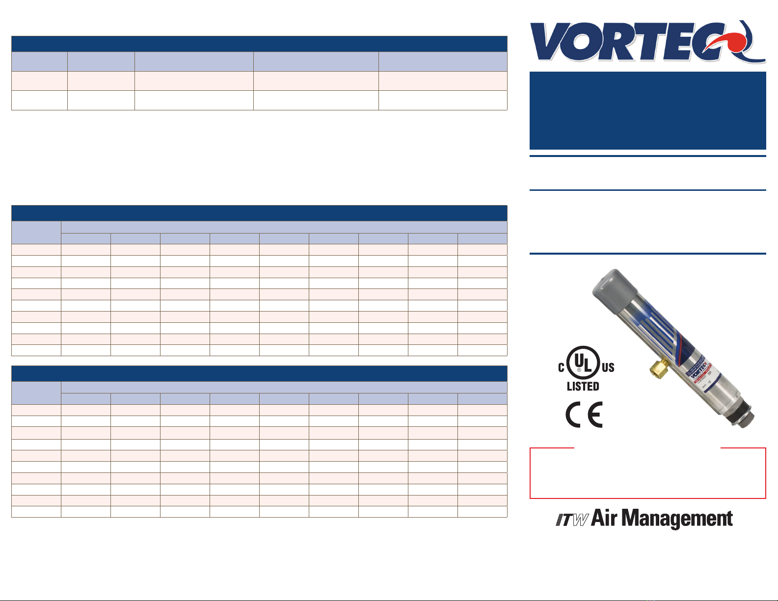
intrOductiOn
AVortex Cooler is designed to use ltered compressed air to
cool industrial cabinets without the use of any refrigerants.
An internal Vortex tube lowers the temperature and
pressure of the compressed air supplied to the enclosure.
Hot air in the cabinet is vented to the surroundings through
a built in relief valve in the Vortex Cooler.
Vortex Coolers can be used with or without electric
thermostats and solenoid valve.
cOMpreSSed air SuppLy
The compressed air supply must be ltered to remove
water and dirt using a 5 micron or smaller lter. Failure
to use a lter may cause clogging (and freezing) of the
compressed air paths inside the Vortec product. Filter
recommendations are given in Table 1.
Filter elements must be changed on a regular basis.
Frequency of change is determined by the condition of
the compressed air supply. Filters should be installed in
the compressed air supply line as close as possible to the
Vortec product.
The appropriate size of compressed air supply line should
be selected to ensure optimal performance of the Vortec
product. Please refer to Table 2 to determine what supply
line size is recommended for your application. Contact
Vortec at 1-800-441-7475 for further assistance.
Maintenance
Vortec Cooler systems have no moving parts and can be
disassembled for cleaning.
inStaLLatiOn and OperatiOn
For best results, Type 12 Vortex Coolers should be installed
in a vertical orientation on a at horizontal surface at the
top of the cabinet, or in a horizontal orientation on a at
vertical surface on the side of the cabinet.
Vents in the cabinets must be covered and sealed to
ensure cooling efficiency and to keep out ambient air.
When a thermostat is supplied with a Vortex Cooler
system for Type 12 enclosures, the thermostat can be
easily readjusted using the temperature indicator dial. All
wiring must be installed in an approved conduit.
Installation procedures:
1. Cut two 1-1/8” (29 mm) (3/4” knockout size) holes in the
enclosure.
2. Insert the Vortex Coolers into the cut-outs and secure
with the locknuts.
3. Perforate the ducting kits with several 1/8” (3 mm) holes
and secure to interior of enclosure.
4. Attach the ducting kits to the cold outlets of the Vortex
Coolers.
5. Connect compressed air lter and/or valve and
thermostat, to the Vortex Coolers (wire thermostat
directly to solenoid valve). Pipe ttings are provided
for connecting the compressed air lter, solenoid valve
(in 7970 models) and Vortex Coolers. Additional piping
must be provided by the end user.
6. Connect compressed air supply to the lter.
trOubLeShOOting
Insufficient airow may be caused by the following:
1. Undersized compressed air line size.
2. Compressed air pressure too low.
3. Partial or complete blockage of internal compressed air
path, due to dirt.
Insufficient cold air temperature may be caused by:
1. Compressed air line temperature too high.
2. Water vapor in the compressed air supply.
3. Loose cold cap. This may occur if not tightened properly
after disassembled for cleaning.
If trouble persists, please contact Vortec at 1-800-441-
7475.
LiMited warranty
Vortec compressed air products manufactured by ITW
Air Management will be replaced or repaired if found
to be defective due to manufacture defect within ten
years from the date of invoice. Refer to our website
www.vortec.com for full warranty details and limitations.
ITW Air Management makes no specic warranty
merchantability or warrant of tness to a particular purpose.
1. Do not operate a Vortex Cooler at compressed air
pressures above 150 psig (10.3 Bar).
2. Do not operate at line temperatures above 110oF
(43oC).
3. Avoid direct contact with compressed air.
4. Do not direct compressed air at any person.
5. When using compressed air, wear safety glasses
with side shields.
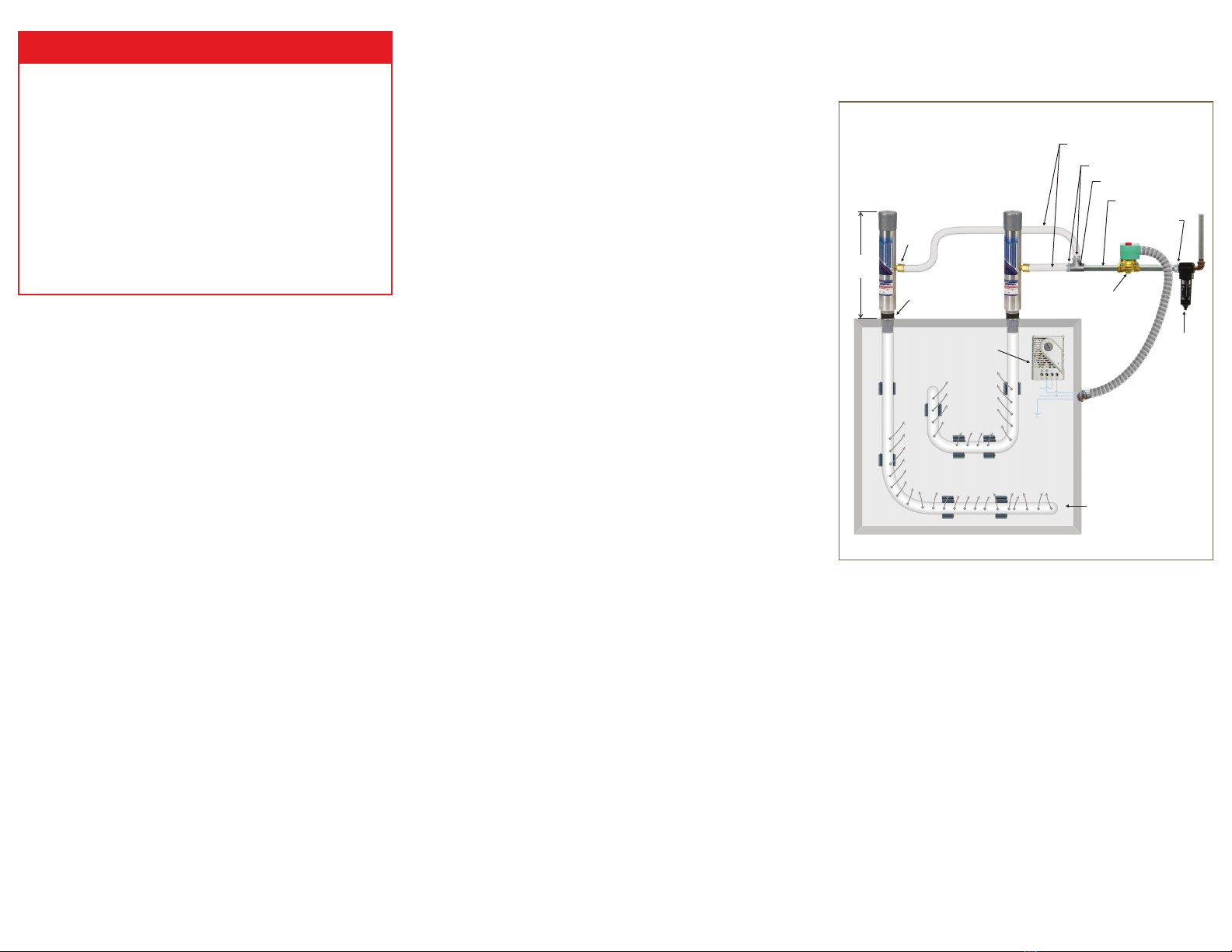
VOrteX cOOLer aSSeMbLy
(Drawings shown below are not to scale)
Models 7870, 7970
generaL Safety cOnSideratiOnS
warning: cOMpreSSed air cOuLd cauSe
death, bLindneSS Or injury
10-3/4
(273 mm)
1-1/8" Hole
1/4" NPT (F)
1/4" piping or 3/8" inside diameter hose
(keep as short as possible – user supplied)
1/2" pipe nipple (2 supplied)
1/2 x 1/4" pipe reducer (2 supplied)
3/4" x 1/2" pipe
reducer (supplied)
Solenoid NEMA 12
110v / 60 Hz
Air Filter
Ducting Kit
Cold Air
Line
Neutral
Ground
Thermostat
Cold Air
1/2" Tee