OPERATION
To regulate the Cold Air Gun temperature, turn the
adjustment knob at the back of the Gun. Turning the knob
counterclockwise will reduce the temperature and volume
of the cold air stream. When operating the Cold Air Gun at
compressed air pressures below 100 psig (6.9 Bar), it is
possible to open this valve too far so that there is no cold air
ow. Turn the knob clockwise to increase the cold air ow
and temperature.
Maximum cooling capacity (not the coldest temperature)
occurs when there is a balance between cold air volume
and cold air temperature drop. In other words, there must
be an adequate volume of cold air at a reasonable cold
temperature to achieve the maximum cooling effect. In
normal operation, this will occur when the adjustment knob
is turned 1/4 to 3/8 open (counterclockwise) from the full
closed (clockwise) position.
MAINTENANCE
The Cold Air Gun has no moving parts (other than the
adjustment knob), and requires only ltered compressed air
for proper operation.The Cold Air Gun can be disassembled
for cleaning, if necessary, as shown above. If the Gun has
been disassembled for cleaning, the Cold Cap must be
reassembled tightly to ensure that the Generator seats
tightly against the body assembly. A loose Cold Cap will
reduce cooling capacity.
1. Do not operate the Cold Air Gun at air pressures
above 150 psig (10.3 Bar).
2. Do not operate the Cold Air Gun at line temperatures
above 110
o
F (43
o
C).
3. Avoid direct contact with compressed air.
4. Do not direct compressed air at any person.
5. When using compressed air, wear safety glasses
with side shields.
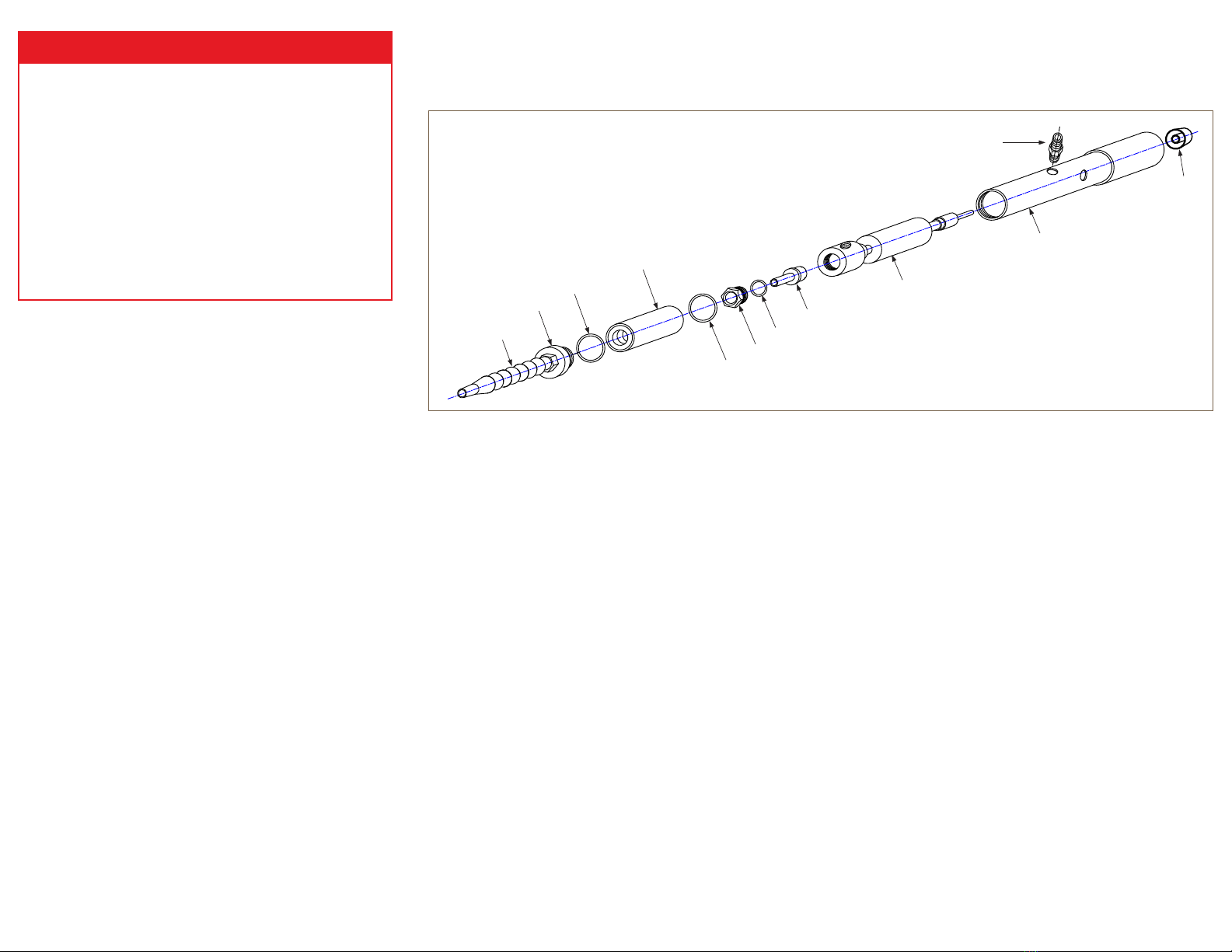
ADJUSTABLE COLD AIR GUN ASSEMBLY
LIMITED WARRANTY
Vortec compressed air products manufactured by ITW Air
Management will be replaced or repaired if found to be
defective due to manufacture defect within ten years from
the date of invoice.
Refer to our website www.vortec.com for full warranty
details and limitations. ITW Air Management makes no
specic warranty merchantability or warrant of tness to a
particular purpose.
Insufficient airow may be caused by the following:
1. Undersized compressed air line size.
2. Compressed air pressure too low.
3. Partial or complete blockage of internal compressed air
path, due to dirt. See Maintenance section for cleaning
instructions; and Compressed Air Supply section for lter
recommendations.
4. Insufficient compressed air volume.
5. Loose cold cap. This may occur if not tightened properly
after disassembled for cleaning.
If trouble persists, please contact Vortec at 1-800-441-7475.
TROUBLESHOOTING
The compressed air supply must be ltered to remove water
and dirt using a 5 micron or smaller lter. Failure to use a
lter may cause clogging (and freezing) of the compressed
air paths inside the Vortec product. Filter recommendations
are given in Table 1.
Filter elements must be changed on a regular basis.
Frequency of change is determined by the condition of
the compressed air supply. Filters should be installed in
the compressed air supply line as close as possible to the
Vortec product.
The appropriate size of compressed air supply line should
be selected to ensure optimal performance of the Vortec
product. Please refer to Table 2 to determine what supply
line size is recommended for your application. Contact
Vortec at 1-800-441-7475 for further assistance.
When the desired cold air stream temperature is less than
32oF (0oC), a compressed air dryer may be necessary to
prevent ice formation on the inside of the Vortec product.
COMPRESSED AIR SUPPLY
INSTALLATION
A Cold Air Gun can be installed by directly plumbing to the
appropriately-sized hard piped compressed air source that
does not exceed 150 psig (10.3 Bar).
INTRODUCTION
A Cold Air Gun is a device that converts ltered, 100 psig
(6.9 Bar) compressed air into a cold airstream.
The Adjustable Cold Air Gun consumes 15-35 SCFM (425-
990 SLPM) of compressed air and is perfect for a wide range
of industrial spot cooling and dry machining applications.
(Drawings shown below are not to scale)
Model 610, 620 and 630
GENERAL SAFETY CONSIDERATIONS
WARNING: COMPRESSED AIR COULD CAUSE
DEATH, BLINDNESS OR INJURY
Flexible Nozzle
Assembly
Threaded Cap
-219 size O-ring
Cold Air Mufer Assembly
-029 size O-ring
Cold End Cap
-116 size O-ring
Generator (see Table 1)
Main Body Assembly
Blue Encapsulation Sleeve
Adjustment
Knob
Inlet Fitting


