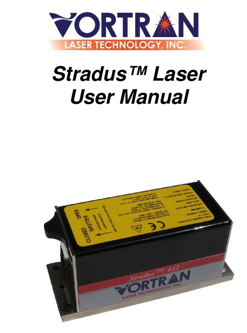
Vortran Stradus VersaLase User manual

Stradus VersaLase™
User Manual


www.vortranlaser.com
Table of Contents
1.0 List of Tables i
2.0 List of Figures ii
3.0Symbols iv
4.0 Laser Safety 1
4.1 A Note Regarding Compliance 1
4.2 Laser Classification 1
4.3 Observations 1
4.4 Laser Safety Labels 1
4.5 Electrical Safety 2
4.6 Optical Safety 2
4.7 Vortran Laser Safety Features 2
4.7.1 Protective Housing 2
4.7.2 Power Indicator 2
4.7.3 Interlock 3
4.7.4 Laser Emission Indicators 3
4.7.5 Computer Control 4
5.0 System Information 5
5.1 System Features 5
5.2 System Description 5
5.3 Power Supply Requirements and Protection 5
5.4 Environmental Operating Conditions 5
5.5 Block Diagram 6
6.0 System Installation 7
6.1 System Installation Checklist 7
6.2 Unpacking and Inspection 8
6.3 Laser System Mounting 9
6.3.1 Laser System Drawings 9
6.3.2 Heat Sink Requirements 9
6.3.3 Mounting Hardware 9
6.3.4 Torque Specification 10
6.4 Electrical Connections 11
6.4.1 Power Supply Connection 11
6.4.2 USB Connection 11
6.4.3 RS-232 Connection 12
6.4.4 I/O Connection 13
7.0 OEM Laser Installation 16
7.1 OEM Installation Checklist 16
7.2 System Chassis Drawings 16
7.3 Heat Sink Requirements 17

www.vortranlaser.com
7.4 Laser Mounting Hardware 17
7.5 Torque Specifications 17
7.6 Power Supply Requirements 18
7.7 System I/O Connector 19
7.8 USB Connection 21
7.9USBDriver 21
7.10 RS-232 Connection 21
8.0 System Operation 22
8.1 System Operation Checklist 22
8.2 Laser Warm-up and Standby 22
8.3 Laser Emission 22
8.3.1 Near-field Beam Quality 22
8.3.2 Far-field Beam Quality 23
8.3.3 External Power Control 24
8.4 Digital Modulation (Optional) 25
8.4.1 Specification for Standard Single Mode Diode Lasers 25
8.4.2 SMB Connection 25
8.4.3 Operation 26
9.0 Computer Controlled Operation 27
9.1 USB Connection 27
9.2 RS-232 Connection and Setup 27
9.3 Command and Query Summary 28
9.3.1 Global Commands 28
9.3.2 Global Queries 28
9.3.3 Laser-Specific Commands 29
9.3.4 Laser-Specific Queries 30
9.4CommandDetail 31
9.5QueryDetail 40
9.6 Fault Codes 47
10.0 Stradus VersaLase™ Control Software 48
10.1 Supported Operating Systems 48
10.2CDContents 48
10.3 Software Installation 48
10.4 USB Driver Installation 51
10.5 Menu Items 53
10.5.1 File Menu 53
10.5.2 View Menu 53
10.5.3 Connect Menu 54
10.5.4 Help Menu 54
10.6 Home Screen 55
10.6.1 Status 56
10.6.2 Laser Hours 56

www.vortranlaser.com
10.6.3 Digital Modulation 57
10.6.4 External Control 58
10.6.5 Emission 59
10.6.6 Laser Output 59
10.6.7 Base Plate Temperature 60
10.6.8 Diode Temperature or Module Temperature 61
10.6.9 Controller Temperature 61
10.7 Terminal Screen 62
10.7.1 Script Mode 63
10.7.2 Control Buttons 63
10.7.3 Load Script File 63
10.7.4 Clear Window and Save Session File Log 64
10.8 Tool Bar 64
10.9 Status Bar 65
11.0Tutorials 66
11.1 External Laser Power Control 66
11.2 Laser Enable Modulation 68
11.3 Digital Modulation (Optional) 69
12.0 Troubleshooting Guide 70
12.1 Resolving Faults 70
12.2 Temperature Faults 72
12.3 Laser at Half Power 72
13.0 Glossary 73
14.0Warranty 74
15.0 Returning Systems for Service 75
16.0 Contact Vortran Laser Technology 76

www.vortranlaser.com
i
1.0 List of Tables
Table
Description
1
Page
Packing List
8
2
RS-232 Protocol
12
3
DE-25 Pin Connections
13
4
I/O Connector Pin Descriptions
19
5
RS-232 System Connection
21
6
Digital Modulation Specifications
25
7
RS-232 Pin Descriptions and Protocol
27
8
Command and Query Summary
30
9
Command Detail
39
10
Query Detail
46
11
Fault Codes
47
12
RS-232 Connections and Communication Protocol
66
13
Fault Code Resolution
71

ii
www.vortranlaser.com
2.0 List of Figures
Figure Description Page
1 Laser Safety Label Location 1
2 Power Indicator 3
3 Interlock Diagram 3
4 Laser Emission Indicators 3
5 System Block Diagram 6
6 System Dimensions 9
7 System Torque Pattern 10
8 System Power Connector 11
9 DE-25 Pin Diagram 14
10 System Dimensions 16
11 System Mounting Dimensions 17
12 System Mounting Torque Pattern 18
13 System Power Connector 18
14 I/O Connector DE-25 Pin Diagram 19
15 Near-Field Beam Image 23
16 Far-Field Beam Image 23
17 SMB Connector Location 25
18 Pulse Mode Example 26
19 USB Connector Location 27
20 Software Installation Welcome Screen 49
21 Software Installation Location Screen 49
22 Software Installation Confirmation Screen 50
23 Software Installation Complete Screen 50
24 USB Driver Installation Utility 51
25 Windows Security Message 51
26 Installing USB Driver Progress Message 52
27 USB Driver Installation Complete Message 52
28 File Menu 53
29 View Menu 53
30 Connect Menu 54
31 Help Menu 54
32 Home Screen 55
33 Laser Status Indicator 56
34 Laser Hours 56
35 Digital Modulation 57
36 External Control 58
37 Laser Emission Indicators 59
38 Laser Power and Current Indicators 59
39 Base Plate Temperature Indicators 60

iii
www.vortranlaser.com
40 Diode/Module Temperature 61
41 Terminal Screen 62
42 Script Mode 63
43 Execute Script 63
44 Load Script File 64
45 Clear Window/ Save Session Log 64
46 Tool Bar 64
47 Status Bar 65
48 External Control Setting 67
49 Laser Enable and Signal Ground DE-25 Pins 68
50 Digital Modulation Control 69
51 Fault Indicator and Signal Ground DE-25 Pins 70

www.vortranlaser.com
iv
3.0 Symbols
ESD – This symbol is used to alert the user of hazards associated
with Electro-static Discharge.
Laser Radiation – This symbol is used to alert the user of hazards
associated with optical radiation emitted from the laser.
CE Mark – This symbol represents the European Directive
Conformite Europeenne" to certifiy that a product has met EU
health, safety, and environmental requirements, which ensure
consumer safety. Manufacturers in the European Union (EU) and
abroad must meet CE marking requirements where applicable in
order to market their products in Europe.
Ground – This symbol represents electrical ground.
USB – This symbol is used to reference Universal Serial Bus
Communication.

www.vortranlaser.com
No Text on This Page

1
www.vortranlaser.com
4.0 Laser Safety
4.1 A Note Regarding Compliance
The Vortran Stradus VersaLase™ OEM System has features which allow it to be
easily integrated a system which meets CDRH safety requirements, based on
EN60825-1. These features include the interlock, emission LEDs, 5 second
emission delay.
4.2 Laser Classification
The Stradus VersaLase™ is classified as a Class IIIb laser device as specified
by the Center for Device and Radiological Health (CDRH). The device emits
visible or invisible laser radiation from the aperture located in the front of the
laser system chassis. The emitted wavelength(s) and maximum power level(s)
are specified on the laser safety label.
4.3 Observations
If the equipment is used in a manner not specified by Vortran Laser Technology,
the protection provided by the equipment may be impaired.
4.4 Laser Safety Labels
Figure 1
Laser Safety Label

2
www.vortranlaser.com
4.5 Electrical Safety
No hazardous voltages are contained in the Stradus VersaLase™ laser head.
The system does not contain any user accessible components within the system
enclosure. The warranty will void if the enclosure is disassembled.
ESD
Vortran Laser Technology recommends that proper ESD precautions are taken
when handling the laser head. The Vortran Stradus VersaLase™ System is
designed with internal safeguards for protection against ESD. Even with the
tested design safeguards in place, high energy ESD discharge events may cause
damage to the laser system. Vortran Laser Technology recommends handling
and operating the laser system on a grounded work bench or optical table.
4.6 Optical Safety
Based on the properties associated with laser light, special optical safety
precautions are recommended by Vortran Laser Technology. Direct eye
exposure from the laser light emitted from the output aperture located on the
front of the laser head is considered dangerous. Vortran Laser Technology
recommends the use of proper laser safety eyewear when operating the laser
system. The user is advised to wear appropriate safety eyewear for the
wavelength(s) and power level(s) of lasers in their application. The laser output
should be contained in a secure beam path. The user should be aware of
propagation associated with reflective and refractive optical components prior to
laser exposure. The laser emission indicators located on the laser head are
visible even when using laser safety eyewear.
4.7 Vortran Laser Safety Features
4.7.1 Protective Housing – The Stradus VersaLase™ is enclosed in a
protective metal housing. This housing is not intended to be removed by
the user as there are no user-serviceable parts inside the module. If the
housing is removed, the user may be exposed to laser radiation and
electrical shock hazards and all warranties will be void. Please return the
laser or control box to the factory for any required repair or service. The
factory contact information is located at the end of this manual.
4.7.2 Power Indicator – A power indicator, shown in Figure 3 below, is located
on the rear panel of the chassis. This indicator is visible even when using
laser safety eyewear.

3
www.vortranlaser.com
Figure 2
Power Indicator
4.7.3 Interlock- The Stradus VersaLase™ features safety interlock circuitry
which must be closed electrically for laser emission to occur. The electrical
interlock is available at the DE-25 25-pin connector on the rear panel. More
information about the interlock may be found in the Section 6 or 7 of this manual.
Figure 3
Interlock Diagram
4.7.4 Laser Emission Indicators – The Stradus VersaLase™ module includes
emission indicators to indicate emission from each laser module enclosed in the
chassis. The wavelength of the indicators allows them to be viewed when using
laser safety eyewear. The laser emission indicators will illuminate prior to laser
emission and during laser emission. The laser system should be considered
dangerous when the emission indicators are active.

4
www.vortranlaser.com
Figure 4
Laser Emission Indicators
4.7.5 Computer Control – The Stradus VersaLase™ may be controlled by a
computer via USB or RS-232 connections. The status of safety features
such as the electronic laser emission interlock may be monitored by
firmware terminal commands and queries or by using the Stradus
VersaLase™ user interface software.

5
www.vortranlaser.com
5.0 System Information
5.1 System Features
Compact full-featured multi-laser platform with a common control interface
USB or RS-232 remote communication
Control and monitoring available through Stradus VersaLase™ Software
External Analog Power Control (if equipped)
Digital Modulation Control (if equipped)
Field-upgradable multi-laser platform
5.2 System Description
The Vortran Stradus VersaLase™ provides a compact, full-featured, field
upgradeable, multiple laser platform with a common hardware and software
control interface for all lasers in the package. The multiple laser system includes
visible indicators for power and laser emission for each wavelength.
5.3 Power Supply Requirements and Protection
12V +/- 10% (10.5V to 13.5V) at 9 amps
It is recommended that the Stradus VersaLase™ ground is connected to a power
supply which has a connection to Earth ground. Many “brick” style power
supplies do not provide this connection.
5.4 Environmental Operating Conditions
The Vortran Stradus VersaLase™ module is designed for indoor or enclosed use
only. Typical operating temperatures range from 10ºC to 40ºC, based on the heat
sink used to maintain base plate temperatures at or below 50ºC. The Vortran
Stradus VersaLase™ laser can operate at altitudes up to 2000 meters.
Maximum relative humidity is 80% for ambient temperatures up to 31ºC, with a
linear decrease to 50% at 40ºC. The laser system does not emit any type of
pollution.

6
www.vortranlaser.com
5.5 Block Diagram
Stradus VersaLase™ Block Diagram
Figure 5
System Block Diagram

7
www.vortranlaser.com
6.0 System Installation
6.1 System Installation Checklist
Unpack and Inspect the Stradus VersaLase™System
Secure the system to an appropriate Heat Sink
Torque Laser Head to Heat Sink at 20 in-lbs, Using a Progressively Increasing
Cross Torque Pattern
Connect the Power Supply
Connect USB or RS-232 connections if Computer Control is Desired
Connect DE-25 I/O connector to access all I/O signals
If Computer Control is Desired, Install Vortran Stradus VersaLase™ User
Interface Software
Proceed to Operation Section for Additional Information
Note:
The electrical interlock MUST be CLOSED for laser emission to occur!

8
www.vortranlaser.com
6.2 Unpacking and Inspection
Upon receipt of your new Vortran product, inspect the contents of the shipping
box for potential damage from mishandling during shipment. Immediately report
any damage to Vortran Laser Technology.
The VersaLase™ System is designed for custom OEM integration. The contents
of the box are based on specific customer needs. Typically the box will contain
the items listed below.
Description Part Number Quantity
Laser Head See Packing List 1
Laser Control Software CD 10820 1
Mini B USB Cable 10126 1
Table 1
Packing List

9
www.vortranlaser.com
6.3 Laser System Mounting
6.3.1 Laser System Drawings
Figure 6
System Dimensions
6.3.2 Heat Sink Requirements
The Stradus VersaLase™ system is conduction-cooled and requires a heat sink
for operation.
Failure to use a heat sink will overheat the module
Heat sink compound is not required or recommended for mounting.
A heat sink capable of dissipating 75 Watts is required for
laser mounting.
A 32 finish is recommended for the system mounting surface, to
ensure optimum thermal transfer.
A high tolerance heat sink surface flatness is recommended
for mounting.
6.3.3 Laser Mounting Hardware
Recommended mounting hardware for the Stradus VersaLase™ system is
M6 x 6mm or ¼ - 20 x ¼”.

10
www.vortranlaser.com
6.3.4 Torque Specifications
Normal mounting can be accomplished by using the provided hex
key to secure the laser head to the heat sink, by tightening the screws
gradually in a progressing cross pattern. This method should provide
stable thermal and pointing performance. Optimum thermal and pointing
performance is accomplished by securing the laser head to the heat sink,
with a precision torque driver. Torque the laser module to the heat sink by
using a cross torque pattern and progressively increasing torque from
10in-lbs to 15-in-lbs to 20in-lbs. Torque the module in the sequence
shown below.
Figure 7
System Torque Pattern
Table of contents
Other Vortran Measuring Instrument manuals