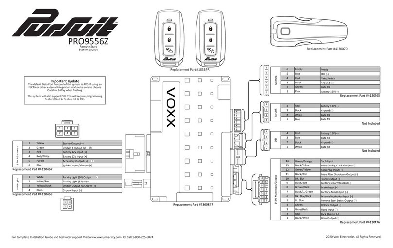
Voxx Pursuit Series User manual

128-9218
1 of 24
1
Model PRO9556CA
Installation Manual
Vehicle Remote Start System
PATENTED: www.voxxintl.com/company/patents
9556C Upgrade New Format Add Timing PASD & Light Blue + DBI Lock, Lock, Lock & Horn 5/2013
Table Of Contents:
BeforeYouBegin Page 2
Wire Harnesses Quick View Page 3 & 4
Installationof theMajorComponents Page 5
Wiringthe 6 Pin MainPower Harness Page 5 & 6
WiringConnector: 12PinAccessoryInput/OutputHarness Page 7 - 9
Wiringthe 4AuxiliaryOutputHarness Page 10
5WireAntenna/ReceiverPush-ButtonSwitch Page 10
2PinDoor Lock/Unlock Harness Page 11-12
2Pin WhiteAuxiliary Output Harness Page 12
2PinTransponderControlOutput Page 12
MonitoringtheVehicle'sEngine Page 13
Diagnostics Page 13
Multi Coil PackApaptor Page 14
TestingYourInstallation Page 14
HoodPinSafetyShutDown Page 14
RemoteStartOverrideMode/ManualShutDown Page 15
NeutralStartSafetyTest Page 15
MechanicalNeutralSafetySwitch Considerations Page 16
KeyInSensorCircuits Page 16 -17
CompletingTheInstallation Page 18
InstallationNotes Page 19
ProgrammingBank1(Transmitter) Page 20
ProgrammingBank2 (Alarm Features) Page 20
SelectableFeatures Page 21
ProgrammingBank3(Remote Start) Page 22
TachRateProgramming Page 22
RFProgrammable Features Bank3 Page 23
Wiring Diagram Page 24

128-9218
2 of 24
2
Before You Begin
PROFESSIONAL INSTALLATION IS
STRONGLYRECOMMENDED
Rolldownwindowtoavoidlockingthekeysinthevehicleduring
installation.
Avoidmountingcomponentsorroutingwiresnearhotsurfacesor
nearmovingpartslike the steering wheel as it mayprevent proper
operationofthevehicle.
Tapeor loom wires under thehoodanddashfor protection as well
appearance.
Usegrommets when routingwiresthroughmetalsurfacestoprevent
chafingand shorting.
UseaDigital Multi Meter for testing andverifyingcircuits. DONOT
USEA"TESTLIGHT" OR "COMPUTER SAFE PROBE" as these
canset off airbags or damage sensitivevehicle computers and
electronics.
For technical support go to www.prestigecarsecurity.com
or call 1 800 225 6074
This device complies with FCC Rules Part 15 Operation is subject to the following two conditions
(1) This device may not cause harmful interference and
(2) This device must accept any interference that may be received, including interference that may cause
undesired operation.
NOTE:The manufacturer is not responsible for any radio or TV interference caused by unauthorized modifica-
tions to this equipment. Such modifications could void the user’s authority to operate the equipment

128-9218
3 of 24
3
6 Pin Power / Start Harness #1123742
1
2
3
4
5
6
Purple Accessory(+)
Blue Ignition1 (+)
Red Battery 2 - 12V (+)
Red/White Battery 1 - 12V (+)
Yellow StarterOutput
Green Ignition2 (+)
4 Pin Alternate Output Harness #1122585
1
2
3
4
Black/Blue FactoryDisarm / Pulse Beffore Start(-)
Black/Green FactoryArm/PulseAfterStart(-)
Black/Red PulseAfterShutdown(-)
Black/Yellow PulseDuringCrank(-)
Green/Orange TachometerInput
12 Pin Main Wiring Harness #1123751
1
2
3
4
5
6
7
8
9
10
11
12
Yellow/Black (+)OutputToControl FactoryAlarm
Green/Yellow DieselWaitToStartInput
Brown PositiveInhibitShutdownInput(+)
Brown/Black BrakeShutdownInput(+)
Black Chassis Ground
Gray/Black NegativeInhibitShutdownInput(-)
LightBlue Ground OutputWhile Running (-) 300mA
Grey ShutdownInput(-)
White ParkingLightOutput
White Parking Light Input
NoConnection

128-9218
4 of 24
4
2 Pin Door Lock Output Harness #1122242
1
2Red (-)Lock / (+) Unlock
Green (+)Lock / (-) Unlock
2 Pin Transponder Output Harness #1123292
1
2Red Battery(+)100mA
Black (-)Output WhileRunning100mA
2 Pin Auxiliary Output Harness #1124258
1
2Black/White HornOutput (-) 300mA
DarkBlue TrunkRelease Output(-)300mA
5 Pin Antenna Harness Part # 1123906

128-9218
5 of 24
5
This Remote Start/Alarm System is designed to be used with Automatic Transmission- Fuel Injection
Gas or Diesel Vehicles Only!
INSTALLATION OF THE MAJOR COMPONENTS:
CONTROLMODULE: PART# 1365331
Selectamounting location insidethepassenger compartment (upbehindthe dashboard). Themounting
location selected must be within 24" of the ignition switch wiring harness to allow connection of the 6 pin
main wiring harness. Be certain that the chosen location will not interfere with proper operation of the
vehicle. Avoid mounting the module to or routing the wiring around the steering shaft/column, as the
moduleor wiringmay wraparoundorblockthesteeringwheelpreventingpropercontrolof thevehicle. The
modulewillbe secured afterall wiring is completedwhich will allowcompleteaccess until thejobis done.
Do Not Mount The Module In The Engine Compartment, as it is not waterproof.
HOOD PIN SWITCH: PART# 1363699
Thepin switchincludedin thispackage isintendedfor protectingthehood areaof thevehicle.In allcases,
theswitchmust be mounted toagrounded metal surface. Whenthepin switch is activated,(hoodopen),
itwillsupply a groundtothe input wireactivatingthe alarm. Inaddition,the hood switchisrequired for the
safety shut down of the remote start unit. If the vehicle is being worked on, this hood switch prevents the
remote start activation even if the RF command to start is issued. This switch must be installed in all
applications. Failure to do so may result in personal injury or property damage.
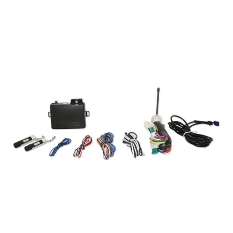
THE PUSH-BUTTON PROGRAM SWITCH/LED/RECEIVER/ANTENNA: PART # 1181202
The Superheterodyne ReceiverAntennaAssembly provided with this unit allows routing from below the
dashboard formaximum operatingrange. Choosea locationabove thebelt line(dashboard) ofthe vehicle
for best reception. Special considerations must be made for windshield glass as some newer vehicles
utilizea metallicshieldedwindow glass thatwill inhibitorrestrict RFreception. Inthesevehicles, routethe
antenna toward a rear window location for best reception. Secure the antenna with double stick tape
provided. IMPORTANT!
DONOTPLUGTHESIXPIN MAINPOWERHARNESS ORTHEMULTIPININPUT/OUTPUTHARNESS
INTO THE CONTROL MODULE UNTILALL CONNECTIONS TO THE VEHICLE HAVE BEEN MADE.
AFTER SELECTING YOUR TARGET WIRES AS DEFINED BELOW, DISCONNECT THE NEGATIVE
BATTERYCABLEFROMTHE VEHICLEBATTERYPRIORTOMAKINGANYCONNECTIONS.
NOTE: Do not remove the fuse holders from this wire harness. Fuses must be used and located
as close as possible to the power source for adequate protection of the vehicle.
WIRING THE 6 PIN MAIN POWER HARNESS: PART #1123742
NOTE: Do not remove the fuse holders from this wire harness. Fuses must be
used and located as close as possible to the power source for adequate pro-
tection of the vehicle.
1 VIOLET Wire: Accessory Output
Connect this wire to theAccessory wire from the ignition switch. This wire will show + 12 volts when the
ignition switch is turned to the "ACCESSORY" or "ON" and "RUN" positions, and will show 0 volts when
the key is turned to the "OFF" and "START" or "CRANK" positions.
2 BLUE Wire: Ignition 1 Output
Connect this wire to the ignition 1 wire from the ignition switch. This wire will show +12 volts when the
ignition key is turned to the "ON" or "RUN" and the "START" or CRANK" positions, and will have 0 volts
when the key is turned to the "OFF" and "ACCESSORY" positions.
ForDieselApplications, thiswiremust beconnectedto theignitioncircuit thatpowersthe glowplugs if the
vehiclerequires glow plugpre-heating. (SeeselectablefeatureBank 3 #11)
128-9218
6 of 24
6
3 Fused RED WIRE: + 12 Volt Battery 2 Source
Locate the vehicle battery wire(s) at the ignition switch. Verification: These wires will register voltage in all
positions of the ignition switch. Connect the Red wire to the vehicle's battery wire. This wire provides power for
the start relay and the accessory relay.
4 Fused RED/WHITE WIRE: + 12 volt Battery 1 Source
Locate the vehicle battery wire(s) at the ignition switch. Verification: These wires will register voltage in all
positions of the ignition switch. Connect the Red w/White wire to the vehicle's battery wire. This wire provides
power for the control circuit as well as the ignition 1 and ignition 2 relays.
5 YELLOW Wire: Starter Output
Careful consideration for the connection of this wire must be made to prevent the vehicle from
starting while in gear. Understanding the difference between a mechanical and an electrical
Neutral Start Switch will allow you to properly identify the circuit and select the correct installa-
tion method. In addition you will realize why the connection of the safety wire is required for
all mechanical switch configurations.
Failuretomakethis connection properly can result in personal injuryandproperty damage.
Inallinstallations itisthe responsibility oftheinstalling techniciantotest the remotestartunit and ensure
that the vehicle cannot start via RF control in any gear selection other than park or neutral.
Inboth mechanical andelectrical neutralstartswitchconfigurations, theconnectionof theYellow wirewill
bemadeto the low currentstartsolenoid wire of theignitionswitch harness. This wirewillhave +12 volts
when the ignition switch is turned to the start (crank) position only. This wire will have 0 volts in all other
ignition switch positions.
NOTE: This wire must be connected to the vehicle side of the starter cut relay (when used). For the
electrical neutral switch configuration, this connection must be made between the starter inhibit relay,
( when used ) and the neutral safety switch as shown in the following diagram.
Failure to connect this wire to the ignition switch side of the of the neutral safety switch can result in
personalinjury andpropertydamage.
SEENEUTRALSTARTSAFETYTESTFOR FURTHERDETAILS.
YELLOWSTART WIRE DETAIL
6 GREEN Wire: Ignition 2 Output
Connect this wire to the ignition 2 wire from the ignition switch. This wire will show + 12 volts when the
ignition key is turned to the "ON" or "RUN" position and is some cases the "START" or CRANK" position.
This wire will show 0 volts when the key is turned to the "OFF" and "ACCESSORY" positions.
NOTE: Seeprogramming information(Bank 3Selection #2)concerning thiswire toallow outputduringthe
"START"mode.

128-9218
7 of 24
7
WIRING CONNECTIONS: 12 Pin Accessory Input/Output Harness PART #1123751
1 Yellow/Black Wire: + 12 VoltAlarm By - Pass Output
NOTE: You must disconnect the ignition input of the alarm from any other wire that it is presently connected
to in the vehicle.
Thiswireprovidesa+12Voltoutputwhentheignitionkeyisturnedtothe“ON”position,and0Voltswhentheignition
key is “OFF” or when the vehicle is running under the control of the remote starter.
This wire should be connected to the ignition input of the alarm system.
This output will allow you to remote start the vehicle while leaving the alarm armed, and to lock/unlock the doors
while running under control of the remote start unit.
2Green w/ Orange Wire: Tachometer Input Signal
This wire will continually monitor the engine's tach rate while the unit is under power of the Remote Start
module. This wire will be routed to the vehicle ECM tach input or through the firewall into the engine
compartment and connect to the negative side of the ignition coil.This Remote Start unit learns the tach
rate of the vehicle and in most cases will operate properly from one multi coil pack regardless of the
number of cylinders. If the vehicle has a single coil unit for each cylinder, it may be necessary to connect
this wire to more than one cylinder for proper tach reference. See Multi Coil PackAdaptor wiring detail
shownlater in thismanualfor additional information.
Note: ForHybridmodeselection, Bank 3 feature selection 5, this connectionisnot required, the unit will
start the vehicle and run the allotted time based on feature selection and crank duration.
3 Black Wire: Chassis Ground Source
Connectthe Black wiretoa knownvehicleground source ortoa solid cleanmetal part ofthe chassis. Be
certain to remove any paint or grease and secure this wire with a self tapping screw and ring terminal.
4 Gray w/ Black Wire: Negative Inhibit Input 2
Anytimethegrayw/blacktracerwireisgrounded,theRemoteStarterwillstopoperating,evenifthesignal
isreceivedfromthetransmitter.
Ifthebrakelightswitchinthevehicle switchesgroundtothebrakelightcircuit,connecttheGrayw/Black
tracewiretotheoutputofthebrake lightswitch.Ifthebrakelightswitchinthevehicleswitches+12Volts,
do not use the Gray w/ Black wire; see Brown w/ Black tracer wire.
5 Light Blue Wire: Ignition 3 / Ground While Running Output
This wire provides a 300mA ground output that becomes active 3 seconds before the Remote Start Unit initial-
izes, and remains grounded while running plus an additional 2 seconds after the Remote Start Ignition 1 turns
off. In all of the applications described below, a relay will be required. The Light Blue wire can be used to
accommodate the following situations:
A. Shock Sensor By Pass:
If there is Shock Sensor used with an alarm system and it is not shunted during the Remote Start activation
period, then vibration from the running vehicle can cause the alarm to trigger. In this case, connect the Light
Blue Wire to terminal #86 of a external relay. Connect terminal #85 of the relay to a fused + 12 volt battery
source. Cut the shock sensor trigger wire and connect one end of the cut wire to terminal #30 and the other
end of the cut wire to terminal #87a. Just before the Remote Start unit is activated, the relay contacts will open,
preventing the shock sensor's operation until the Remote Start unit shuts off.

128-9218
8 of 24
8
B.Ignition 3 Output:
Some newer vehicles use a third ignition wire, which is required to start and keep the vehicle's engine running.
If this is the case, connect the Light Blue wire to terminal #86 of an external relay. Connect terminal #30 & #85
to a fused + 12 volt battery source rated for a minimum of 25Amp. Connect terminal #87 to the third ignition wire
in the vehicle.
C.GM VATSKey Override:
If the vehicle has the General Motors VATS system installed, you will need to bypass the system while the
vehicle is operating under the control of the Remote Start Unit. To Do This;
1. Measure the resistance of the resistor pellet on the ignition key then select a resistor within 5% of the key's
value from the resistor pack supplied.
2. Locate the pair of VATS wires in the vehicle, usually a pair of thin gauge wires running from the ignition switch
to the VATS control module.
Note: These wires are typically White w/ Black trace and Violet w/ Yellow trace, however in later model Cadillacs,
they are run through an orange sleeve, and are either both Black, both Yellow, or both White wires. Consult
the factory service manual for additional information.
3. Connect the Light Blue Wire from the Remote Start Unit to terminal #86 of an external relay. Connect terminal
#85 of the relay to a fused + 12 volt battery source.
4. Cut (#1) wire (as shown), and connect the ignition switch side of the cut wire to terminal #87a of the relay.
Connect the other side of the (#1) wire to terminal #30.
5. Connect the previously selected resistor from terminal #87 to the second (#2) wire (as shown).
NOTE: The above information and following diagram is for the GM VATS system only.
6 Green/Yellow Wire: Diesel Wait To Start Input
TheGreen/Yellowwireofthe12pinconnector willconnect toadieselvehicle'sglowplugwire. Whentheunitreceives
a start command, this wire must go to + 12 then to ground to allow the crank sequence to begin. When ignition #1
is activated by the remote start unit, the glow plug circuit gets energized, (+ 12 volts), when the glow plug circuit of
the vehicle drops the + 12 volts, which effectively grounds the wait to start input, then 500mS later the starter will
engage. This wire can also be connected to the Glow Plug Bulb wire in the vehicle if this bulb wire gets + 12 volts
when the ignition comes on and drops low when the glow plug circuits temperature is reached. Be sure to fuse the
wire with a 1 Amp Fuse when connecting to a high current circuit such as a factory glow plug wire. The fuse should
be installed as close to the high current wire as possible. If you are installing this unit in a Gasoline vehicle, this
wire is not used.
7 Gray Wire: Negative Inhibit Input 1
ConnecttheGRAYwiretothepreviouslymountedhoodpinswitchprovided.Thiswirewillberoutedthrough
the firewall into the engine compartment. It is necessary to use an existing grommet when passing wires
throughthefirewalltopreventshortcircuiting.ThisisanimportantsafetyfeatureoftheSystem,failuretouse
this feature can result in serious injury. Route the wire to the pin switch and connect it using the bullet
connectorprovided.

128-9218
9 of 24
9
8 Brown Wire: Positive Inhibit Input 1
Anytime +12VoltsisappliedtotheBrownwire,theRemote Starterwill stopoperating, evenif thesignal is
receivedfromthetransmitter.
Ifthevehiclehasafactoryinstalledhoodpinswitchandthatswitchprovides+12Voltstoanunderhoodlight,
the Brown wire can be connected to the existing pin switch.
9 Brown w/ Black Wire: Positive Inhibit Input Plus Trigger When Armed
TheBrown w/BlackTracewire providesan instantshutdownfortheRemote StartControl modulewhenever
it gets + 12 volts also triggers the alarm when armed. If the Brake lights switch in the vehicle switches + 12
volts to the brake light circuit, connect the Brown w/ Black trace wire to the output side of the brake switch.
This will allow the Remote Start to shut down if an attempt is made to operate the vehicle without the key
while running under the control of the Remote Start. In most vehicles, in order to shift into gear, the brake
pedal must be depressed. The brake input will in turn cause the remote start unit to shut off.
10 No Connection
11 White Wire: Parking Light Flasher Output
This wire is the normally open contact of the on board parking light flash relay. Connect this wire to the
vehicle's parking light feed wire. This is the wire that gets switched on, either (+) or (-), when the vehicle's
parking light switch is activated.
12 White Wire: Parking Light Flasher Input
Thiswireis thecommoncontact oftheon board parkinglight flasherrelay. Ifthevehicle youareworking on
has +12 volt switched parking lights, connect this wire to a fused + 12 volt source. (Max. 15Amps)
NOTE: Ifthevehicle's parking lights areground switched, connect thiswireto chassis ground.

128-9218
10 of 24
10
WIRING THE 4 PIN AUXILIARY OUTPUT HARNESS Part#1122585
Theauxiliary4 pin connectorprovideslow current outputs tocontrolvarious functions inthevehicle during
differentstagesof theRemoteStartunit's operation.Understandingthese outputsandthe timein whichthey
occur will allow you to determine if they are needed for the particular vehicle you are working on as well as
how to use them.
1 Black w Blue Trace Wire: Pulsed Ground Output Before Start
The Black w/ Blue Trace wire will provide a 1 second 300 mA pulsed ground output 1.5 second before the
remotestart unit activates aswellas when thetransmitteris used todisarmthe system.Typicaluse for this
output would be to disarm a factory theft deterrent system to prevent false triggering of the factory alarm
when the remote start unit engages or when the system is used to unlock the doors. This will also activate
when the transmitter is used to disarm/unlock the system
NOTE: Thisoutputcan be selectedto operate likethedoor lock outputasset in alarmfeature setting #1 by
selecting feature #17 in Bank 3 for 2 Chirps.
2 Black w/ Light Green Trace Wire: Pulsed Ground OutputAfter Start
TheBlack w/Light GreenTrace wirewillprovidea1second300mA pulsedground outputafter thevehicle is
startedundercontrol oftheremote startunit.Typicallythis wirewillbe usedto re-lockthevehicle doorsif the
doorsunlock automatically whenthefactory anti-theftsystemis disarmed. Thiswire will alsoactivatewhen
the transmitter is used to arm/lock the system.
3 Black w/ Red Trace Wire: Pulsed Ground OutputAfter Shutdown
TheBlack w/Red Tracewirewillprovidea 1second 300mA pulsedgroundoutputafterthe remotestart unit
shuts down. This output will occur regardless of whether the circuit times out or is manually terminated.
Typically this output will be used to re-lock the vehicle doors if the doors unlock automatically when the
ignition circuit transitions to off.
4 Black w/ Yellow Trace Wire: Ground Output During Start (Crank)
The Black w/ Yellow Trace wire will provide a 300 mAground output while the starter output of the remote
start unit is active. This output can be used to activate the Crank Low/Bulb Test wire found in some GM
vehicles. This wire is also referred to as the ECM wake up wire in some vehicles.
NOTE: Theoutputs above arelowcurrent outputs andmust be usedwitha relayifthe circuit's requirement
is more than 300 mA.
5 Wire Antenna/Receiver Program Push-Button Switch/LED Connector: Part # 1123906
Plugthe previouslyrouted antennaconnectorfromtheantennareceiverassembleintothematingconnector
ofthe control module.Thisconnector supplies 12volts,groundandRF datainput,LED Cathode,andValet
Enable to and from the antenna receiver and the remote start module. Be certain these connectors are
firmly seated making good contact to the control unit.

128-9218
11 of 24
11
2 Pin Door Lock/Unlock Harness: (WhiteConnector)300mA Part # 1122242
1 Red Wire: (-) Lock or (+) Unlock
TheRed wire providesa(-) Negative Pulsewhen locking anda(+) PositivePulsewhen unlocking.
2 Green: (+) Lock or (-) Unlock
TheGreen wire providesa(+) PositivePulsewhen locking anda (-) NegativePulse when unlocking.
3 Wire Ground Switched Door Lock Circuits:
In this application, the Red wire of the door lock harness provides a ground pulse during the arming se-
quence, or pulsed ground lock output. Connect the Red wire to the low current ground signal wire from the
factory door lock switch to the factory door lock relay.
TheGreen wire ofthe door lockharness provides aground pulseduringthe disarmingsequence,or pulsed
ground unlock output. Connect the Green wire to the low current ground signal wire from the factory door
unlock switch to the factory door unlock relay. See the following diagram for Wiring Detail.
3 WireGround Switched Door Lock/Unlock Wiring Detail
3 Wire Positive Switched Door Locks:
In this application, the Red wire of the door lock harness provides a + 12 volt pulse during the disarming
sequence,orpulsed 12 volt unlockoutput.Connect the Redwireto the low current12volt signal wire from
the factory door unlock switch to the factory door unlock relay.
TheGreen wireof thedoorlockharnessprovidesa+12voltpulseduringthearmingsequence,orpulsed12
volt lock output. Connect the Green wire to the low current 12 volt signal wire from the factory door lock
switch to the factory door lock relay. See the following diagram for Wiring Detail.
3 Wire Positive Switched Door Lock/Unlock Wiring Detail

128-9218
12 of 24
12
NOTE: Resistive Circuits, Multiplex Circuits As Well As 4 Wire Polarity Reversal and 5 Wire
Alternating 12 Volt Door Lock Control Circuits
These applications require the use of additional components which may include relays, fixed resistors, or
forconvenience, a DoorLockInterface. Refer totheAUDIOVOX Door LockWiringSupplement andorthe
Audiovoxfax backservice forinformationonyourparticularvehicleforproperlyconnectingtothesetypesof
circuits.
2 Pin White Auxiliary Output Harness Part#1124258
Blue Wire: LowCurrent TrunkRelease Output300mA
This wire pulses to ground via an independent RF channel from the keychain transmitter. This is a
transistorized, low current output and should only be used to drive an external relay coil.
WARNING:Connectingthiswiretothehighcurrentswitchedoutputoftrunkreleasecircuitswilldamagethe
control module. To use a relay to connected to this wire, connect this wire to terminal 86 of the
AS - 9256 relay (or equivalent 30Aautomotive relay) connect terninal 85 of the relay to + 12 Volts and
wire the remaining relay contacts to perform the selected function of this output.
Black w/ White Trace Wire : Horn Output 300mA
The black w/ white trace wire is provided to beep the vehicle’s horn. This is a transistorized low current
output, and should only be connected to the low current ground output from the vehicle’s horn switch.
Ifthevehicle uses a+12 VDC horn switch,thenconnect the blackw/white trace wire toterminal86 of the
AS9256relay( or an equivalent 30Amp automotive relay ), andconnectrelayterminal 85 to a fused + 12
VDC battery source. Connect relay terminal 87 to the vehicle’s horn switch output, and connect relay
terminal 30 to a fused + 12 VDC battery source.
2 Pin Transponder Control Output: (YellowConnector) Part # 1123292
a. When selected for while remote start on, the Black wire will be active at the same time ign. 3 be
comes active, and will remain active all the time the unit is operational under the control of the remote
start.
b. When selected for output during the start sequence, the Black wire will be active at the same time Ign.
3 becomes active, and will remain active until the vehicle has started. This will be used for one time
read transponder circuits.
c. When the unit is selected for until ignition off, the Black wire will become active at the same time ign.
3 becomes active and will remain active even after the key take over and until the ignition in the vehicle
is turned off. This will allow the unit to be used for continuous read transponders circuits.
1 Black: 250mA Output (-)
The black wire switches on when the remote start is activated and will stay on as programmed in the
remotestartfeature Bank3 Feature12.
2 Red: 250mA Output (+) 12 Volts Constant
Thisoutputis intended toallowthe control ofatransponder bypass interfacemoduleor transponder
bypass relay.

128-9218
13 of 24
13
Monitoring The Vehicle's Engine: (ProgramFeature #5 Bank3)
There are 4 ways that the remote start monitors the engine running, one or the other must be selected for
your application for the remote start to operate correctly.
1)VOLTAGESENSE SETTING:
The unit will monitor the voltage level of the battery during remote start, wait for the voltage to drop while
cranking,then lookforthe voltagelevelto goabove the levelit wasbeforethe vehiclebeganto crankwhich
indicates the vehicle is running. Feature #14 of Bank 3 must be set for preset time or the voltage sense
feature will not operate indicated by the parking lights flashing 7 times.
2)TACHRATESETTING:
1. Turn the ignition key to the On position.
2. Press and release the valet/program push button switch 3 times.
3. Immediately turn the ignition key Off.
4. Press and hold the valet/program push button switch, then start the vehicle using the key.
5. When the unit senses the tach signal, the parking lights will begin to flash.
6.Release thevalet/programpushbutton switch.The parkinglights willturnon forthree secondstoindicate
that the learned tach signal is stored and the unit is out of the tach learn mode.
NOTE:If theunit failsto learntach ratedue toan impropertachometer connectionor apoor tachsource, the
parkinglightswillnot flash.Tocorrect thissituation, locateandconnecttheGreen/Orange wireto theproper
tach signal, and then repeat the tach learn routine.
3) DBI TACH SETTING
Selectingthissetting in theoptionmenu indicates thatyouhave a DBImoduleand have determinedthata
tach signal is available for the vehicle you are connecting to. The unit will look at the DBI data port for the
tachsignal. Ifthevehicle failsto start, orthe unitflashes7 times,recheck theDBImanual toinsurethat tach
isavailablefor your vehicle.Ifnot the tachconnectionwire, Green/Orange mustbeused.
4)HYBRID SETTING:
Selectingthissetting intheoption menu allowsforHybrid vehicles. Also feature#14 of Bank3must be set
for preset time or the Hybrid feature will not operate indicated by the parking lights flashing 7 times.
CRANKAVERAGING:
WhenFeature 14Bank3 isset forcrankaveraging, theremote startunitconstantly monitorsand learns the
cranking patterns of the vehicle each time the car is started with the key. The vehicle must be started at
least 4 times with the key for the crank averaging circuit to begin its monitoring the vehicle's engine.
DIAGNOSTICS:
Enter Bank 3 and turn on selectable feature # 9 as described on the front pages of this manual.
NOTE: Diagnosticmodeis atemporarymode. Once youhaveaccessed thediagnosticmode, the unitwill
pausefor two secondsthenbegin toflashthe laststoredshut downcode.This code willbe displayed three
times in succession, then the unit will automatically exit the diagnostic on mode.
Theparking lights willflasha number oftimes indicating thereasonfor the lastremote start shutdown.The
light flash indications are as follows:
1 Flash Run timer expired
2 Flashes Low or no tach signal (RPM)
3 Flashes Positive inhibit wire activation
4 Flashes NA
5 Flashes RF shutdown, Remote signal received, or manual start trigger wire reactivated.
6 Flashes High tach signal (RPM)
7 Flashes Tach signal has not been learned
8 Flashes Negative inhibit wire

128-9218
14 of 24
14
Multi Coil PackAdaptor: (Optional)
The multi coil pack adapter, is designed for use with vehicles that do not respond to single coil tach
programming. Althoughthetach resolutionofthis circuit is designedtointerface direct with mostvehicles,
there may be an occasion where the following circuit may be required. Construct the adaptor as shown
below.
To use the adaptor, the Green/Black wires must connect to the negative side of the ignition coil(s).
1. For vehicles utilizing independent coils per cylinder, connect the three Green/Black leads to alternate
coils.Toachieveoptimum performancethecoil signalsmustbe evenlydistributed.Thisis accomplished
byfirst mappingoutthefiringorderofthe enginein groupsofas indicatedbelow.Drawacircle aroundany
ofthe columns.TheGreen/Black wiresshould beconnected tothenegative (-)terminal oftherespective
cylinder number which appears in any of the circles.
2. For vehicles utilizing 2 cylinder firing per coil pack, connect Green/Black to the tach side of each coil
pack. For 8 cylinder, four coil systems, connect to any of the three coils.
3. ConnecttheYellowwiretoa+12volt ignition1 source.Thiswire willhave+12 voltswith theignitionin the
on and start position and have 0 volts with the ignition in the off position.
4. ConnecttheGreen wire to the (Green)or (Orange/Green)tachinput of theAudiovox remote startunit.
TESTINGYOURINSTALLATION:
WARNING!! Thefollowingproceduremustbeperformedafterthe installationofany RemoteStartDevice.It
is the responsibility of the installing technician to complete these tests. Failure to test the unit in the
followingmannermay result inpersonal injury,propertydamage, or both.
HOOD PIN SAFETY SHUT DOWN:
Theintentof the hoodpinsafety shut down istoprevent the Remote Startunit from beingactivatedwhile a
mechanicor vehicleowneris performingnormal routinevehicle maintenance.
To test the integrity of this circuit:
1. With the drivers window in the down position, start the vehicle using the RF transmitter.
2. Reach inside the car and pull the hood release.
3. Raise the hood and confirm that the remote start unit shuts down.
Iftheunit fails thistest,recheck your pinswitchconnection to theGray/Blackwire of theRemoteStartUnit.
DONOT RELEASETHIS VEHICLETO THECONSUMER UNTILYOU CONFIRMTHE
OPERATION OF THE HOOD PIN SAFETY SHUT DOWN FEATURE.

128-9218
15 of 24
15
REMOTESTARTOVERRIDE MODE/ MANUALSHUT DOWN:
Theintent of theremotestart override/manual shut downcircuit is toallowthe vehicle operatorto prevent
operationofthe Remote StartUnit regardlessofthe RF transmitter operation.
To Enter The Remote Start Override Mode:
1. With the system disarmed/unlocked, and the ignition switch off Press and Hold the pushbutton switch
located on the receiver unit on.
2. Turn the ignition switch on, off, on, off, on, off.
3. The LED begins to flash two short flashes followed by one long flashes and continues this pattern until
returned to normal mode of operation.
Theactionabove putsthe unit intotheRemote Start Overridemodeor vehicle servicemodeand will not
start from the RF transmitter or any other input.
To Exit Remote Start Override Mode:
1. With the system disarmed, Press and Hold the PBLED on.
2. Turn the ignition switch on, off, on, off, on, off.
3. The LED turns off indicating that the R/S unit is fully functional one again.
DONOT RELEASETHIS VEHICLETO THECONSUMER UNTILYOU CONFIRMTHE
OPERATIONOFTHE MANUALSHUTDOWN /ENABLE FEATURE.
NEUTRALSTARTSAFETYTEST:
Theintentof the neutral start switch istoprevent the vehicle from startingwhilethegear selector is in any
positionotherthan Park, orNeutral. When installinga Remote StartDevice, it isimperativethat theYellow
Starter wire be connected to the ignition switch side of the Neutral Start Switch. Consideration for the
placementofa starter inhibit relayis important as wellandshould be connected totheignition switch side
of the Yellow Start Wire.
To test the integrity of the Neutral Start Safety Circuit:
1. Set the vehicle parking brake.
2.Block thedrivewheels topreventvehicle movement.
3. Temporarily disconnect the Brown/Black positive shut down wire from the vehicle's brake switch.
4. Sitting in the vehicle, start the engine using the vehicle's ignition key.
5. Step on the brake pedal and shift the gear selector into reverse.
6. Allowthe transmissiontoshift.When youfeelthe enginepull, donotmove thegear selector justturn the
ignition switch off. DO NOTattempt to remove the key.
7. Keeping the brake pedal depressed, activate the RF transmitter in an attempt to start the vehicle. The
car should not start.

128-9218
16 of 24
16
8. Repeat the above test this time move the gear selector to the drive position.
If the unit attempts to start, failing this test, recheck your Yellow Wire's connection. This wire must be
connected to the ignition switch side of the Neutral Start Switch. If the vehicle you are working on does
not have an Electrical Neutral Safety Switch, it will be necessary to reconfigure the Remote Starts Wiring
toaccommodate the vehicle.The information concerningthe Mechanical NeutralSafety Switch provided
below will help you to determine if the vehicle you are working on has this type of safety switch and will
providealternatewiring methodstoaccommodate this situation.
CAUTION! REMEMBERTO RECONNECT THEBROWN/BLACKNEUTRAL SAFETY WIRE
TEMPORARILYDISCONNECTED INSTEP3
MECHANICALNEUTRALSAFETYSWITCH CONSIDERATIONS:
Mechanicalneutral safetyswitch configurationsdiffer slightlyin thatthey donot offerthe samelevel ofsafety
when installing a remote start device. Often when the ignition switch is turned off while the gear selector is
in any position other than park or neutral, the mechanical function will not allow the key to be turned to the
start position or be removed from the ignition cylinder. This configuration prevents mechanical operation
while the vehicle is in gear but offers no consideration for electrical operation. Because of this potential
problem,thisinstallationrequires the additional connection of asafetywire from the remote start device to
the vehicle Park/Neutral ECM Input or the vehicle key in sensor. This connection will prevent remote start
operation if the key is left in the ignition switch regardless of the gear selectors position.
DO NOT RELEASE THIS VEHICLE TO THE CONSUMER UNTILYOU CONFIRM THE OPERATION OF
THEMECHANICALNEUTRALSAFETYSTART FEATURE.
KEYIN SENSORCIRCUITS:
Ifthevehicle you areworkingon does not haveor you cannot locatetheECM reference wire,thereare
twoalternatives available.Althoughnotpreferred, thevehicleKey InSensormay bereconfiguredto allow
amarginofsafety and will prevent the vehiclewitha Mechanical Neutral StartSwitch from startingingear.
AUDIOVOXADVISESTHATYOU MAINTAINTHE FACTORYCIRCUITWHENEVERPOSSIBLE.The
following two circuits may be used only if the above circuit is not available.
NOTE: When completing an installation using either of the following key in sensor circuits, if the operator
inserts the ignition key while the vehicle is running under the control of the Remote Start, the vehicle will
shut down. This must be explained to the operator as it is in contrast to the normal operation of a vehicle
utilizing an electrical neutral start switch and is inconsistent with the operators manual.
Additionalinformationconcerning Key InSensormethods 1 &2are listed belowand should be reviewed
beforeconsidering eitheralternative.
Method1will allow the safetyrequiredfor the remote start unitandprevent the vehicle fromstartingwhile
in any gear other than Park or Neutral while the key is in the ignition cylinder however, if the key is left in
the ignition switch and the door is left opened, the added relay will be energized causing a 150mA drain
on the battery.
Method2will allow thesafetyrequired for the remotestartunit and preventthevehicle from startingwhile
in any gear other than Park or Neutral while the key is in the ignition cylinder however, the original factory
key in chime module will not alert the owner that the key has been left in the ignition switch. In addition,
this may also effect other warning tones such as the light on reminder.
Thesesituationsshould becarefullyconsidered before alteringthevehicle's wiring andmust be fully
explainedtothe consumer.

128-9218
17 of 24
17
METHOD 1
To connect to the key in sensor as shown in method 1:
1. Locate the control wire that connects the drivers door pin switch to the key in sensor switch.
2. Cut this wire and connect the ignition cylinder side to chassis ground.
3. Locate the key in sensor switch wire that connects the chime module to the ignition cylinder .
4.Cut this wireand connect theignition cylinder sideto terminal 30of a P&BVF45F11 orequivalent relay.
5. Connect the cathode (striped) side of a 4002 series diode to this same wire, and connect the (non
striped) side to the negative shut down safety wire (Gray / Black) of theAudiovox Remote Start Unit.
6. Connect terminal 86 of the relay to a fused +12 volt constant battery source.
7. Connect terminal 87 of the relay to the Chime Module side of the previously cut wire in step D.
8.Connectterminal 85 of therelayto the Drivers Doorsideof the pin switchwirepreviously cut instepB.
NOTE:Asecond 4002series diode mayberequired tomaintaintheintegrity ofthehood open,shutdown
circuit.If thisis thecase,itmustbe installedasshown inthe diagramabove. Theanode(NonStriped) side
must be connected to the Gray/Black wire of the Remote Start Unit. The cathode (Striped) side must be
connected to the hood pin switch. If the hood pin switch is also used for an alarm trigger input, be certain
to use the dual diode set up shown earlier in this manual.
METHOD 2:

128-9218
18 of 24
18
To connect to the key in sensor circuit as shown for method 2:
1. Locate the control wire that connects the drivers door pin switch to the key in sensor switch.
2. Cut this wire and connect the ignition cylinder side to chassis ground.
3. Locate the key in sensor switch wire that connects the chime module to the ignition cylinder .
4. Cut this wire and connect the ignition cylinder side to the Remote Start Negative Safety Shut down
Wire Gray/Black, using a 4002 series diode as shown above.
NOTE:Asecond 4002 series diode may be required to maintain the integrity of the hood open, shut
down circuit. If this is the case, it must be installed as shown in the diagram above. The anode (Non
Striped) side must be connected to the Gray/Black wire of the Remote Start Unit.The cathode (Striped)
side must be connected to the hood pin switch. If the hood pin switch is also used for an alarm trigger
input, be certain to use the dual diode set up shown earlier in this manual.
AFTERTHE CONNECTIONOF THENEUTRALSTARTSAFETYWIREAS
INDICATED INANYOF THEPREVIOUSALTERNATE CONFIGURATIONS,THIS CIRCUIT
MUSTBE TESTEDFOR PROPEROPERATION.
Retest by following the steps outlined in the NEUTRALSTART SAFETYTEST section of the manual.
COMPLETINGTHE INSTALLATION
1. Mount the control module up and behind the dash securing it in place with cable ties or screws. Be
certain that the chosen mounting location will not inhibit any of the controls of the vehicle.
2. Securely harness and tie all wiring up and away from all hot and moving parts that they may come in
contact with under the dash board or in the engine compartment areas.
CAUTION: Particularly avoid the area around the steering shaft and column, as wires can wrap around
thesemechanismsand impair thesafeoperation of thevehicle.
3. Apply the Caution Labels supplied with this kit to a conspicuous area in the engine compartment.
Makesureto clean the surfacebeforeaffixing the label.
4. Check the vehicle's wipers, lights, horn, etc.... to insure proper operation.
5. Replace all panels that were removed during installation, and retest the system.
6.Explain all activatedfeaturesand safety systemsassociated with theRemoteStartUnitinstalled. Also
point out the location of the Push-Button LED Override/Valet switch to the customer and explain its
operation.

128-9218
19 of 24
19
INSTALLATIONNOTES

128-9218
20 of 24
20
The transmitters are pre-programmed from the factory. If you find you need to program new or additional
transmittersfollowthe instructions below.
PROGRAMMING BANK 1(TRANSMITTERS):
1. Turn the ignition key to the on position.
2.Pressand release thevalet/programmingswitch 3 times (SirenChirps).
3. Press the Lock Button of each transmitter you want programmed until you hear a chirp from the horn or
siren.
4.Turntheignition switch off.
Theabove actionprogramsthe Lock,Unlock, Start/Trunk,andOption 1buttons ofthesystem ifavailable. For
additionalchannelprogramming see theownersguide found withintheliterature bag packagedwiththis kit.
PROGRAMMING BANK 2 (ALARMFEATURES):
You can enter bank 2 from bank 1 by turning the ignition key off then on from step 4 of Bank 1.
(Siren Short then Long Chirp), or You can also go right to bank 2 by:
1. Turn the ignition key to the on position.
2.Pressand release thevalet/programmingswitch 3 times (SirenChirps).
3.Turnthe ignition keyoffthen on. (SirenShortThen long Chirp)
4.Press the pushbuttonswitchonce to advanceto feature 1,twiceto advancetofeature 2, etc,,,thenuse the
lock button of the transmitter to select the feature setting.
Example to set passive arming:
1. Turn the ignition key to the on position.
2.Pressand release thevalet/programmingswitch 3 times (SirenChirps).
3.Turnthe ignition keyoffthen on. (SirenShortThen long Chirp)
4.Press the pushbutton switch six times to advance to features 6, Pass/ActArm, then use the lock button of
the transmitter to select two chirps "Passive Arm".
5. To exit the programming mode, turn the ignition key off.The program mode is automatically exited when
there is no activity on the pushbutton switch or the transmitter lock button.
This manual suits for next models
1
Table of contents
Other Voxx Remote Starter manuals