9025 USER’S MANUAL: SECTION 3 VIRGINIA PANEL CORPORATION
10/4/13
3-2 For more information visit vpc.com
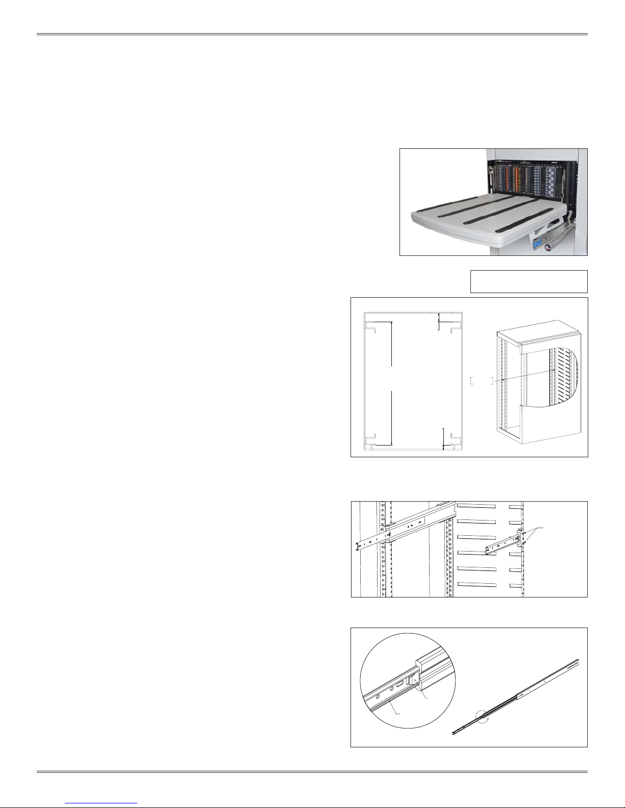
ALWAYS SUPPORT THE RECEIVER AND PLATFORM
WITH THE MOST ROBUST (MIDDLE) SECTION OF
THE SLIDES.
To ensure proper support when extending the receiver and
table away from the rack, stop the receiver and platform at
approximately 6" from the rack. Reach around to the rear of the
receiver to the slides underneath on both sides. Manually extend
the middle section of the slides forward until fully underneath
the platform. The receiver and platform may then be extended
while holding this middle slide in place. If completed properly,
the middle section of the slides will remain underneath the
platform and offer the strongest support.
INSTALLATION - 9025TR
1. Install inner slides back into slide kit in the rack.
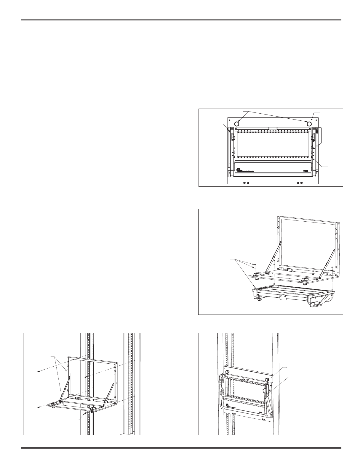
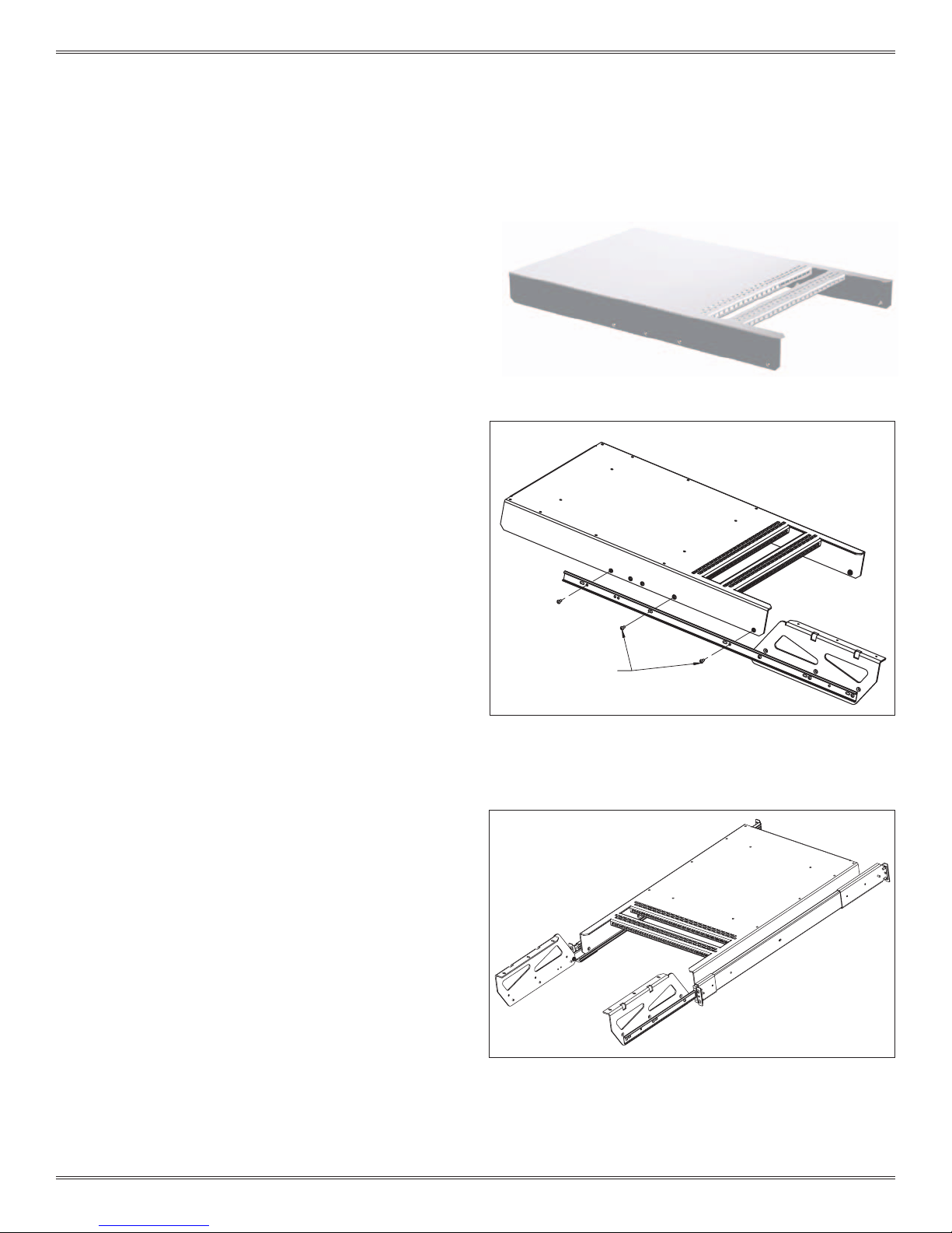
2. Attach the platform mounting anges to the inner slide rails
using the six 8-32 button head screws provided with the
receiver (Figure D). Do not fully tighten down the screws.
3. Install the 9025TR platform/receiver onto the platform
mounting anges with the six 8-32 screws (Figure E). Do not
fully tighten down the screws.
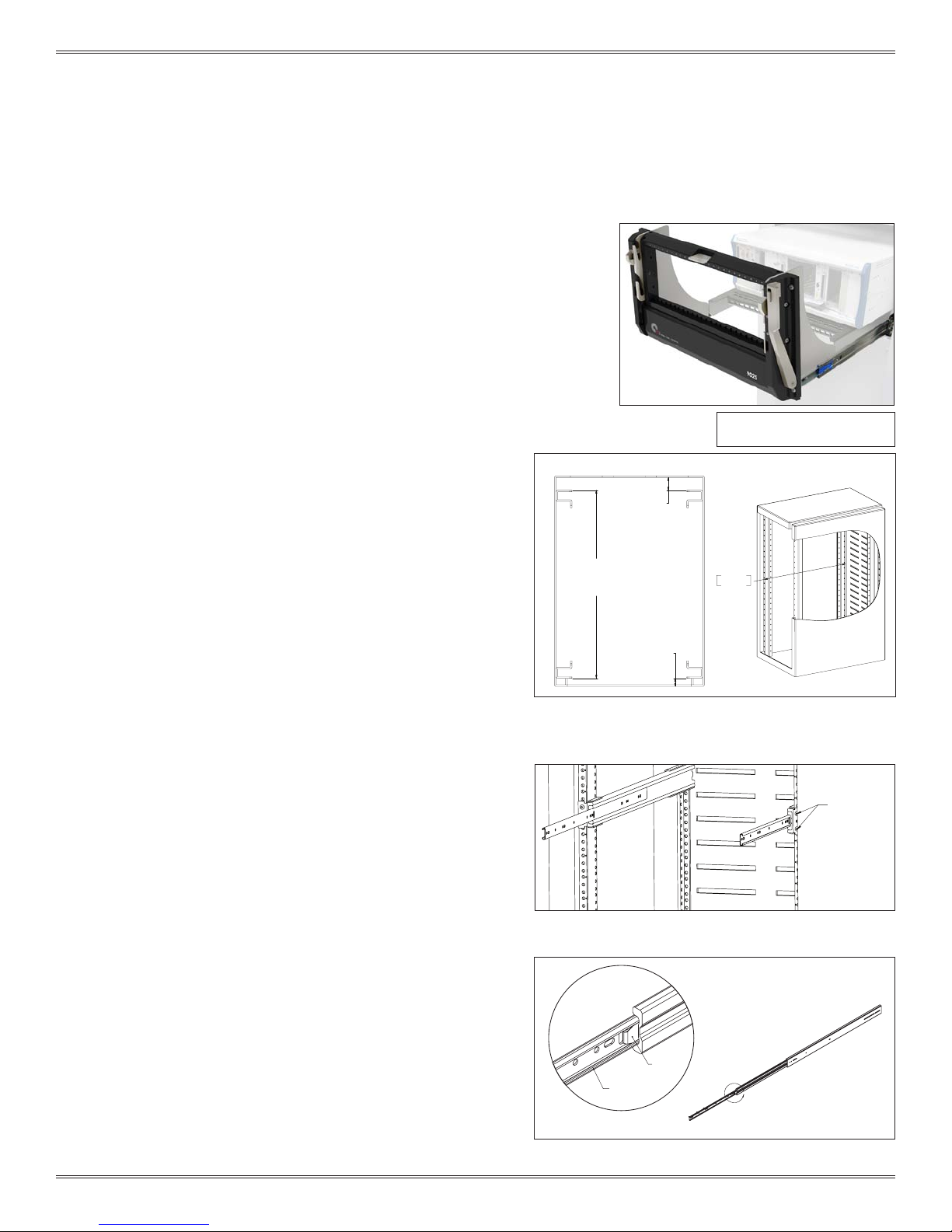
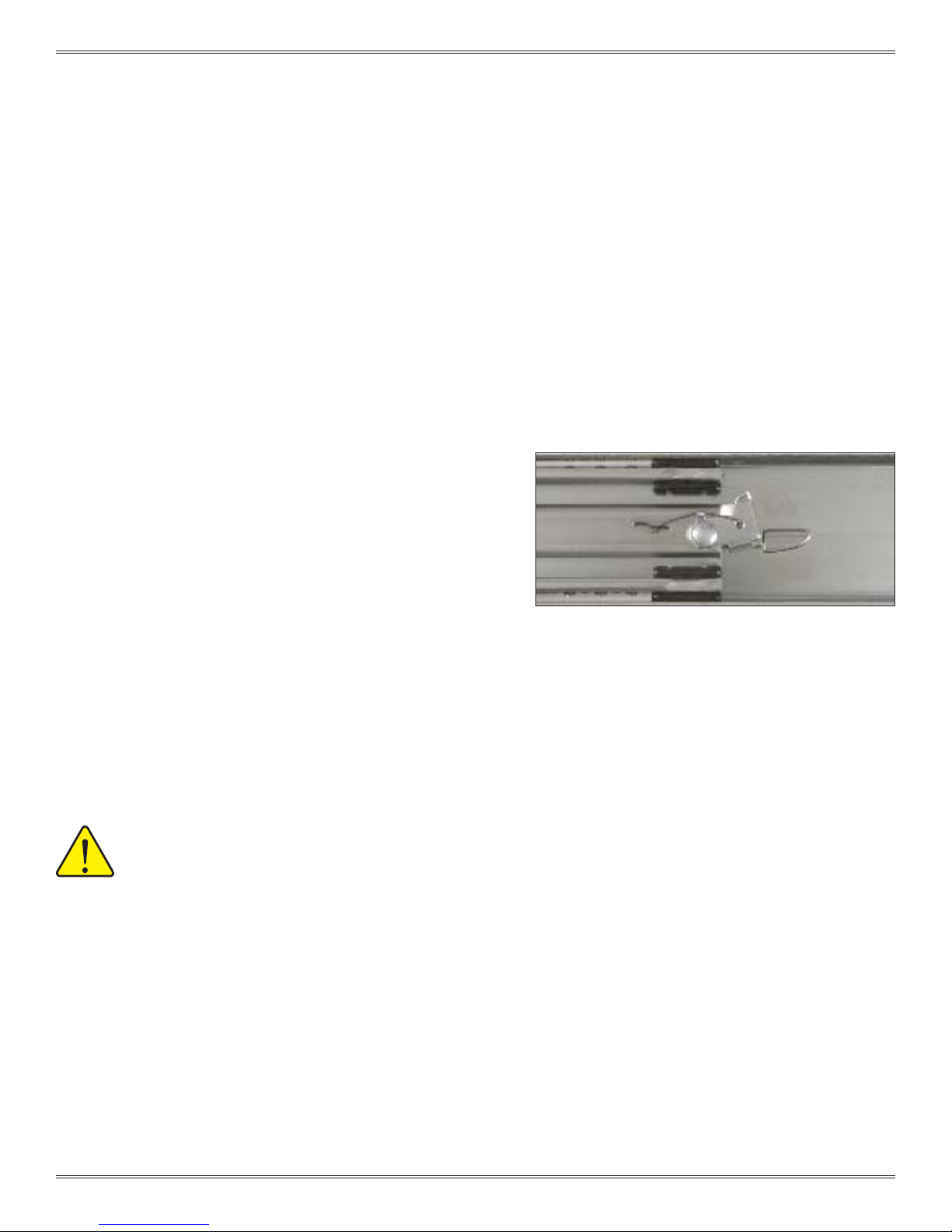
4. Pull the receiver out as far as possible. The slides will lock in
position. Push the blue tabs located on the middle section
of the slides. Apply pressure to push the receiver back in
toward the rack. The smaller inner slides move into the
middle section, which should not move. Push receiver until
it backs into the rack.
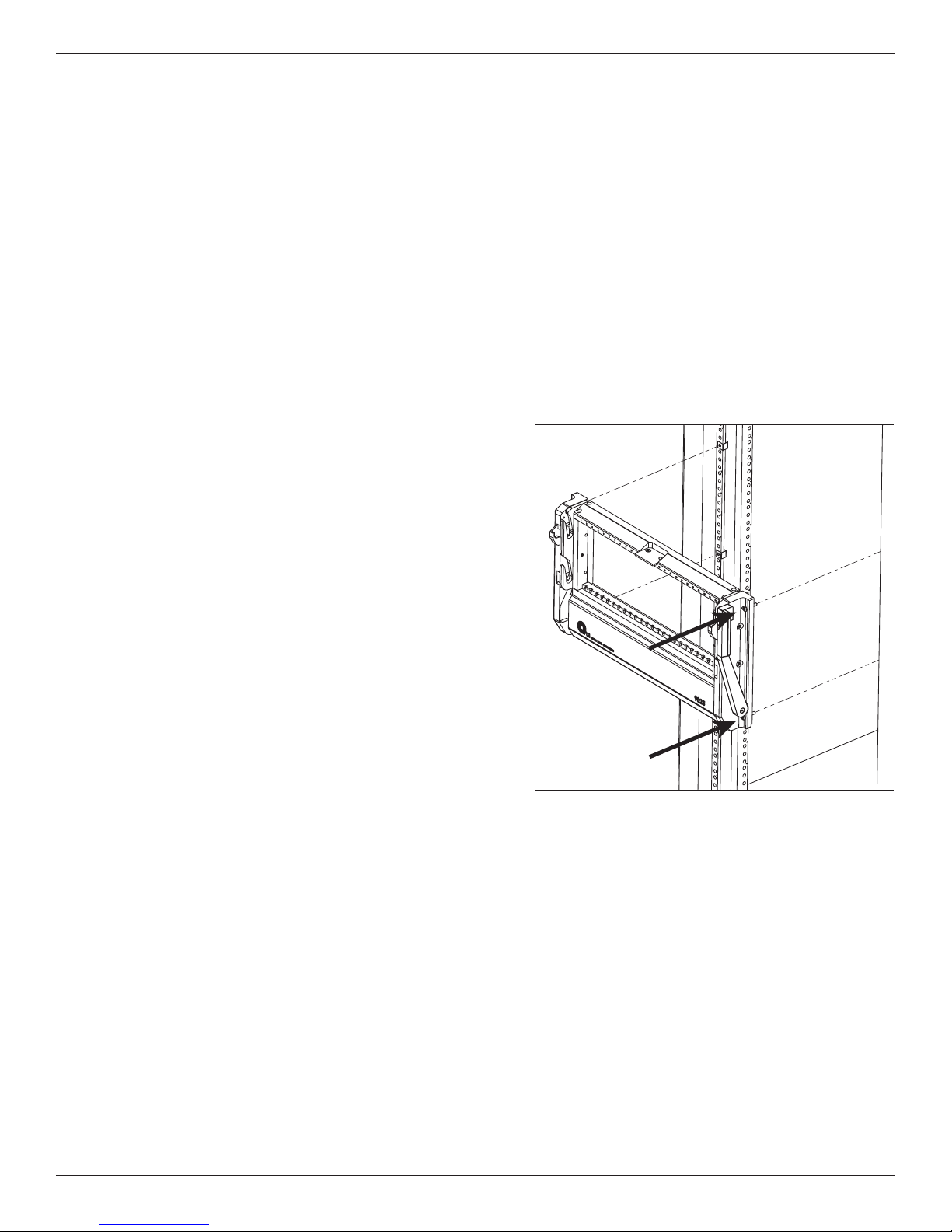
5. Secure the receiver to the rack using the captive 10-32
screws (Figure F). Be sure to lift up on the platform slightly to
ensure an even engagement of the screws.
6. Fully tighten screws in this order:
- 6 8-32 platform mounting screws (as shown in Figure D).
- 6 8-32 button head platform mounting ange screws (as
shown in Figure C).
- 4 front slide mounting screws (from Slide Mounting
procedure, previous page).
- 4 rear slide mounting screws (from Slide Mounting
procedure, previous page).
7. Unscrew the 10-32 captive screws and slide the receiver
out.
9025TR RECEIVER 9025TR PLATFORM
8-32 X .62"
FLAT HEAD SOCKET SCREW
TYP. 6 PLCS.
CAPTIVE 10-32
PANHEAD SCREWS
TYP. EACH SIDE
Figure E. Install 9025TR into platform mounting anges.
Figure D. Attach platform mounting anges to the inner slide
rails.
Figure F. Secure the receiver to the rack with the captive 10-32
screws, taking care to lift up on the platform slightly to ensure
even engagement.
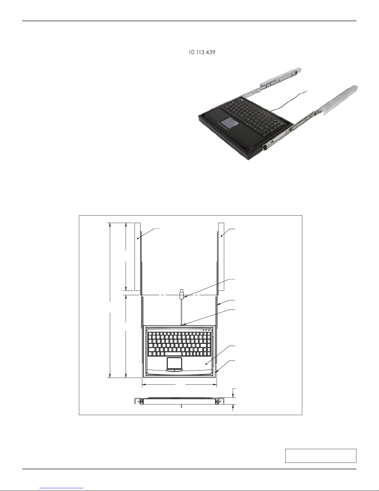
SLIDE CONFIGURATION INSTALLATION - 9025TR
RECEIVER, 9025TR, 25 MODULE, WITH 20" PLATFORM • PART # 310 104 435
28" SLIDE KIT (FITS 26"– 30" DEEP RACKS [660.4 – 762]) • PART # 310 113 451
30"SLIDE KIT (FITS 28"– 32" DEEP RACKS [711.2 – 812.8]) • PART # 310 113 411
36"SLIDE KIT (FITS 34"– 38" DEEP RACKS [863.6 – 965.2]) • PART # 310 113 500