ICON USER MANUAL VPC
07/15/21
For more information visit vpc.com
RETURN TO INDEX
ITA ENCLOSURE INSTALLATION
PART #
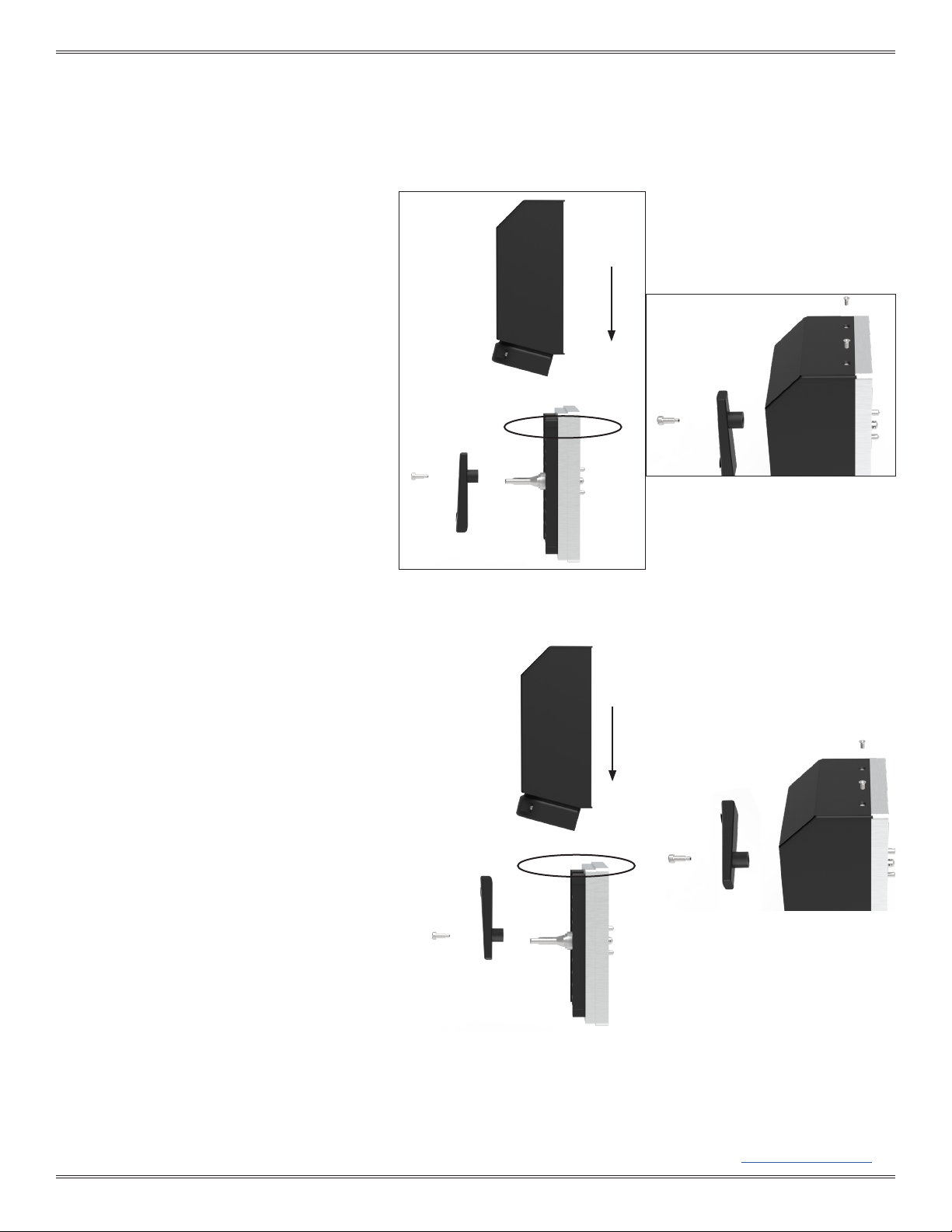
Figure B. Secure the 6-32 slotted shoulder screw
into the handle. Tighten the two captive screws
located at the top of the ITA and three captive
screws located at the bottom of the ITA.
Figure A. The notch area (circled) provides an
option of sliding the enclosure halfway.
COVER INSTALLATION INSTRUCTIONS (CONT’D)
OPTION A: DISENGAGED POSITION
1. Place the cover onto the iCon 960 ITA as shown in
(Figure A). The lip will align with the ITA groove.
2. Slide the cover onto the ITA frame until it is fully
seated against the ITA frame.
3. Place the handle into the enclosure in the down/
disengaged position. (Figure A)
NOTE: Make sure all wires are routed and divided
between the two cable clamp slots.
4. Position the supplied 6-32 shoulder screw into the
handle and tighten with a Flat Head screwdriver
(Figure B).
5. Tighten the captive screws at the top and bottom of
the ITA securing the enclosure to the ITA.
OPTION B: ENGAGED POSITION
1. Place the cover onto the ITA as shown in (Figure C).
The lip will align with the ITA groove.
2. Slide the cover onto the ITA frame until it is fully
seated against the cable clamp.
3. Place the handle onto the enclosure in the up/
engaged position (Figure C).
NOTE: Make sure all wires are routed and divided
between the two cable clamp slots.
NOTE: When choosing to install the ITA Enclosure
using Option B, the handle should be in the up/
engaged position (Figure C).
4. Position the supplied 6-32 shoulder screw into the
handle and tighten with a Flat Head screwdriver
(Figure D).
5. Finally, tighten the captive screws at the top and
bottom of the ITA securing the enclosure to the ITA
(Figure D).
6
Figure C. The notch area (circled) provides an
option of sliding the enclosure halfway.
Figure D. Secure the 6-32 slotted shoulder
screw into the handle. Tighten the two
captive screws located at the top of the ITA
and three captive screws located at the
bottom of the ITA.