VPC SL4 User manual

SL4 USER’S MANUAL
TABLE OF CONTENTS
SECTION 1 RACK/CHAMBER MOUNTING
SECTION 2 TABLE TOP MOUNTING
SECTION 3 ACCESSORIES
SECTION 4 ITA AND RECEIVER ENGAGEMENT
SECTION 5 TROUBLESHOOTING
SECTION 6 PRECAUTIONARY NOTES
10/16/13
For more information visit vpc.com

SL4 USER’S MANUAL: SECTION 1 VIRGINIA PANEL CORPORATION
10/16/13
For more information visit vpc.com
RACK/CHAMBER MOUNTING
SL4 RECEIVER • PART # 310 125 101
The rack mountable SL4 incorporates a mounting bracket that
allows it to be stackable both horizontally and vertically.
Figure B. SL4 mounting brackets.
10.90
276.86
5.20
132.08
.765
19.43
11.60
294.64
3.45
87.63
TOOLS REQUIRED
Phillips head screwdriver
Flat head screwdriver
³/32 Allen Wrench
Custom Rack Design
1. A custom rack is required for mounting the SL4 Receiver for a
rack/chamber application.
2. Determine the number of SL4 receivers that are needed.
3. Determine the vertical spacing of the SL4 receivers. The
height and recommended spacing is shown in Figure A. This
spacing may vary depending on the ITA xture height that
will be used. It must be possible for the ITA xture to clear
the bottom of the SL4 directly above.
4. Determine the number of SL4 receivers that will be placed
side by side. The SL4 mounting bracket allows receivers to
overlap and share a common center mounting bar (Figure
B).
5. The rack should include 10-32 mounting holes for each
receiver. It is recommended that these holes be placed at
.765” intervals, vertically, to allow for future expansion.
13.19
335.03
5.20
132.08
20.32
.80
36.70
1.45
2.71
68.91
Figure A. Recommended height and spacing of receivers.
Page 1 of 3

SL4 USER’S MANUAL: SECTION 1 VIRGINIA PANEL CORPORATION
10/16/13
For more information visit vpc.com
6. Card Guides should be incorporated into the rack design (Figure C).
7. See Figure D for the recommended rack layout.
Figure D. Recommended rack layout.
Figure C. Card guides are not included with the receiver.
CUSTOM CARD GUIDE
CUSTOM CARD GUIDE
.27
6.73
.48
12.19
RACK/CHAMBER MOUNTING, CONTINUED
Page 2 of 3
9.90
251.46
20.80
528.32
XXX
6.00
152.40
17.00
431.80

SL4 USER’S MANUAL: SECTION 1 VIRGINIA PANEL CORPORATION
10/16/13
For more information visit vpc.com
10-32 CAPTIVE MOUNTING SCREW
RACK/CHAMBER MOUNTING, CONTINUED
Page 3 of 3
INSTALLATION
1. Slide the SL4 into the desired position.
2. Use the included 10-32 captive
mounting hardware to secure the
receiver to the rack (Figure E).
Figure E. Secure the receiver to the rack as shown.
TOOLS REQUIRED
Phillips head screwdriver

SL4 USER’S MANUAL: SECTION 2 VIRGINIA PANEL CORPORATION
10/16/13
For more information visit vpc.com
TABLE TOP MOUNTING
SL4 RECEIVER, PART # 310 125 102
The SL4 table top receiver is suitable for a variety of testing
needs.
TOOLS REQUIRED
Phillips head screwdriver
INSTALLATION
1. The SL4 Table Top version may be mounted to the bench top using
the 4 legs with 6-32 tapped holes using the hole pattern shown in
Figure A.
Figure A. Mounting holes for table top.
230.63
9.08
10.06
255.52

SL4 USER’S MANUAL: SECTION 3 VIRGINIA PANEL CORPORATION
10/16/13
For more information visit vpc.com
REAR COVER, TABLE TOP CONFIGURATION
PART # 310 113 506
Rear covers are used to protect the wiring from a tabletop
mounted SL4 receiver to the instruments. The rear cover
includes the necessary mounting hardware.
INSTALLATION
1. Use the provided 4-40 screws to attach the rear cover to the SL4 receiver (Figure A).
OPTIONAL INSTALLATION
1. Rear covers can be permanently mounted to a tabletop using the dimensions provided in Figure B. Hardware is not included.
Figure A. Rear cover, Part # 310 113 506, is designed to attach to the table top SL4 receiver,
Part # 310 125 102.
TOOLS REQUIRED
Phillips Head Screwdriver
4-40 MOUNTING SCREWS
TYP. BOTH SIDES
Figure B. Bottom view of a table top SL4 receiver with a rear cover. The dimensions shown
can be used to place mounting holes to permanently x the assembly on a tabletop.
10.06
255.52
9.10
231.03
2.04
51.82
5.00
127
2.04
51.82

SL4 USER’S MANUAL: SECTION 3 VIRGINIA PANEL CORPORATION
10/16/13
For more information visit vpc.com
KEYING PIN KIT, RECEIVER AND ITA
PART # 310 113 501
The SL4 keying kit includes two pins and screws which
provide six different keying options. The SL4 system is
designed to accept two kits which increase the keying
options to 36.
Figure A. In order to mate the SL4, the keying pins must be in opposite positions on the receiver and ITA.
INSTALLATION
1. Align the keying pin in the desired location. Place the keying pin in the hexagonal opening in the SL4 receiver (See Figure 1).
2. Secure the keying pin with the 4-40 screw.
3. Secure the other keying pin in the corresponding location in the SL4 ITA (Figure A).
TOOLS REQUIRED
3/32 Allen wrench
MATING FACE
FEATURE
KEYING
SL4 RECEIVER
KEYING
FEATURE
KEYING
FEATURE
MATING FACE
SL4 ITA
KEYING
FEATURE

SL4 USER’S MANUAL: SECTION 4 VIRGINIA PANEL CORPORATION
10/16/13
For more information visit vpc.com
MODULE POSITION 4
MODULE POSITION 1
MODULE POSITION 2
MODULE
POSITION
INDICATORS
MODULE POSITION 3
MODULE POSITION 2
MODULE POSITION 1
MODULE POSITION 3
MATING FACE
SL4 RECEIVER
MODULE
POSITION
INDICATORS
MODULE POSITION 4
Prior to engaging an ITA with the receiver for the rst time, ensure all modules (ITA and receiver) are properly installed. This involves
inspection of modules to ensure proper mounting and to verify module positioning. Module positions are shown in Figure A. Modules
must be installed such that Pin 1 of each respective mating receiver and ITA module pair are adjacent. VPC recommends that Pin 1
always be positioned to the left in the Receiver and ITA frames. All ITA modules must match the respective receiver modules. It is crucial
for all modules to be installed properly.
ENGAGEMENT
1. Ensure that the handle is in the full open position.
2. Place the ITA xture on the SL4 platform between the guides
and slide forward until the xture reaches a positive stop.
3. Close the handle to engage the system.
DISENGAGEMENT
1. Open the handle to disengage the system.
2. Slide the ITA xture away from the receiver and remove.
Improper installation will damage the
Modules, and possibly the ITA and/or Receiver.
ITA & RECEIVER ENGAGEMENT
In the event of complications, a trained technician
should be notied immediately to avoid any damage
to the system. This applies to any difculties that may
be experienced during engagement.
Figure A. SL4 Receiver and ITA.
19.16
486.56
15.90
403.94
5.45
138.43
Figure C. When disengaged, the handle will be parallel to the receiver.
Figure B. When engaged, the handle will be perpendicular to the
receiver.

SL4 USER’S MANUAL: SECTION 5 VIRGINIA PANEL CORPORATION
10/16/13
For more information visit vpc.com
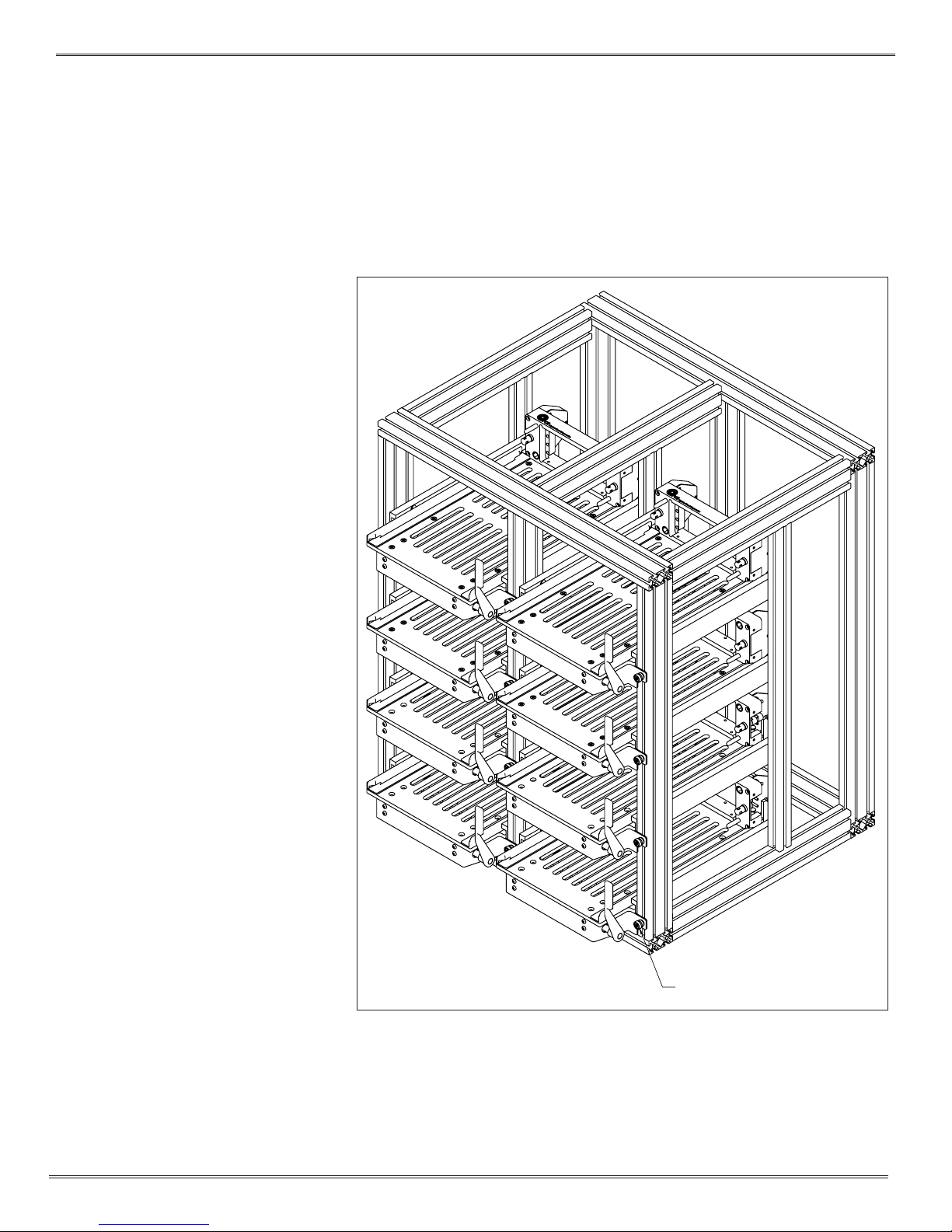
ITA Frame is not lined up when in the process of engagement with receiver
• This may indicate that the ITA was damaged and is out of alignment or that a Module is not mating with its intended module.
• Remove and inspect the ITA for alignment
• Check for foreign objects/tools.
• Inspect the matching of modules - power ITA module to mate with power receiver module, etc.
Excessive force is needed to engage the Handle
• This may indicate that the ITA was damaged and is out of alignment or that a Module is not mating with its intended module.
• Remove and inspect the ITA for alignment. Contact Virginia Panel Corporation – unauthorized user adjustments to System will void
the warranty.
• Check for foreign objects/tools.
• Contact damage may provide enough resistance to notice. Upon replacing a contact in the ITA, the mating contact on the
Receiver side should also be inspected and replaced if necessary.
• Verify the orientation of the receiver and ITA modules.
• Inspect the matching modules - power ITA module to mate with power receiver module, etc.
ITA will not engage with the receiver after diagnosing the above problems
• Contact Virginia Panel Corporation – unauthorized user adjustments to the system will void the warranty.
No continuity upon engagement
• When replacing an ITA contact, the mating contact on the receiver side should also be inspected and replaced if necessary.
• Check wiring and replace if necessary.
• Contact not secured in module.
• A contact may be damaged. Visually check all contacts for damage to potentially isolate damaged pin prior to checking for
continuity with a multi-meter.
A “short ” in the wiring upon engagement
• A damaged contact(s) may cause high resistance. Upon replacing a contact in the ITA, the mating contact on the Receiver side
should also be inspected and replaced if necessary.
• Check wiring and replace if necessary.
Receiver and ITA will not disengage
• This may indicate that the engagement mechanism within the receiver is faulty -contact Virginia Panel Corporation immediately-
user adjustments to system, unless authorized, will void the warranty.
TROUBLESHOOTING
Forceful engagement of the Receiver and the ITA
will result in serious damage to multiple parts of
the system (Modules, Receiver, ITA and Contacts)!

SL4 USER’S MANUAL: SECTION 6 VIRGINIA PANEL CORPORATION
10/16/13
For more information visit vpc.com
The following is a listing of precautionary notes found within this manual and otherwise. They should be noted and followed for the
equipment to operate at an optimum state.
• Never probe a contact without using a mating patchcord as a test lead.
• Never forcefully engage a system if there is an excessive amount of resistance on the handle.
• Never allow an ITA to drop as this may cause misaligned engagement and/or irreparable damage.
• Always insert and extract a contact insertion/extraction tool in line with the contact. Never apply pressure to the side as this may
break either contact or tool. This also applies to forming and enlarging tools.
• It is advisable that power to the interface system be disconnected prior to handling and maintenance.
• Caution should always be used when engaging, making sure that all foreign objects are removed from the system.
• The foremost precautionary step that needs to be taken is to protect the Interface System from damage caused by people
(bumping into the receiver/ITA assembly with a box, chair or electronic equipment for example). To prevent this, VPC recommends
engaging either the ITA or the receiver protective cover to the receiver when not in use.
PRECAUTIONARY NOTES
Table of contents
Other VPC Receiver manuals