OSBBF20A-EN
6/14
ELECTRIC ACTUATOR SPECIFICATIONS
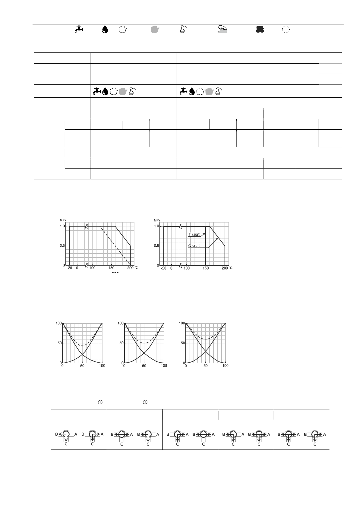
3 way valve: SHUT / Position , OPEN / Position
AD2 HD2 type
Actuator type ( :Voltage code) AD2-300- AD2-700- HD2-300- HD2-700- HD2-02K- HD2-06K-
Voltage 100 / 110 V AC ±10 % 50/60 Hz (Code: 1)
200 / 220 V AC ±10 % 50/60 Hz (Code: 2)
24 V DC (Code: 0)
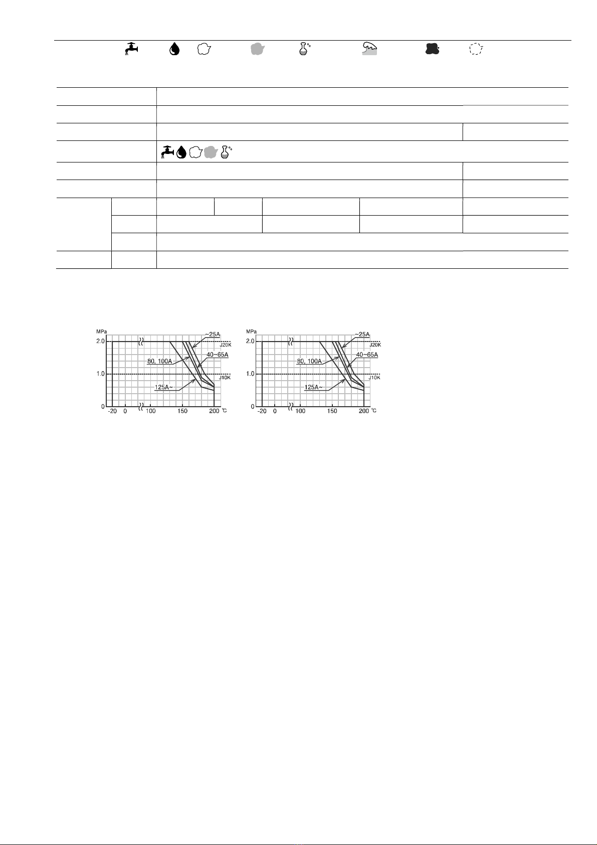
Rated torque [Nm] 30 70 30 70 200 600
Operation time [s] 3 to 4 6 to 10 1 to 2 3 to 5 AC: 8 to 15
DC: 12 to 17
AC: 24 to 45
DC: 36 to 50
Power consumption (Max) [VA] AC: 100
DC: 80
AC: 150
DC: 120
Motor DC motor
Overload protection Current limiter
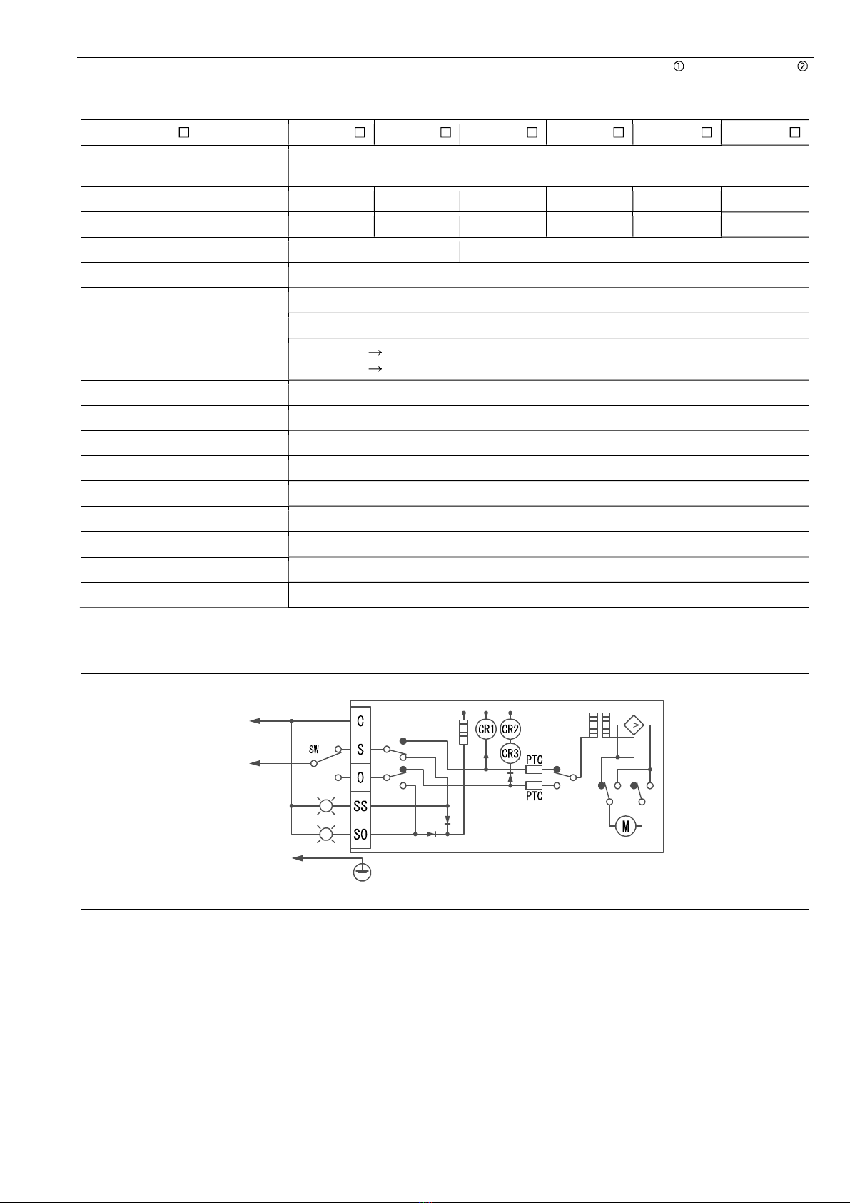
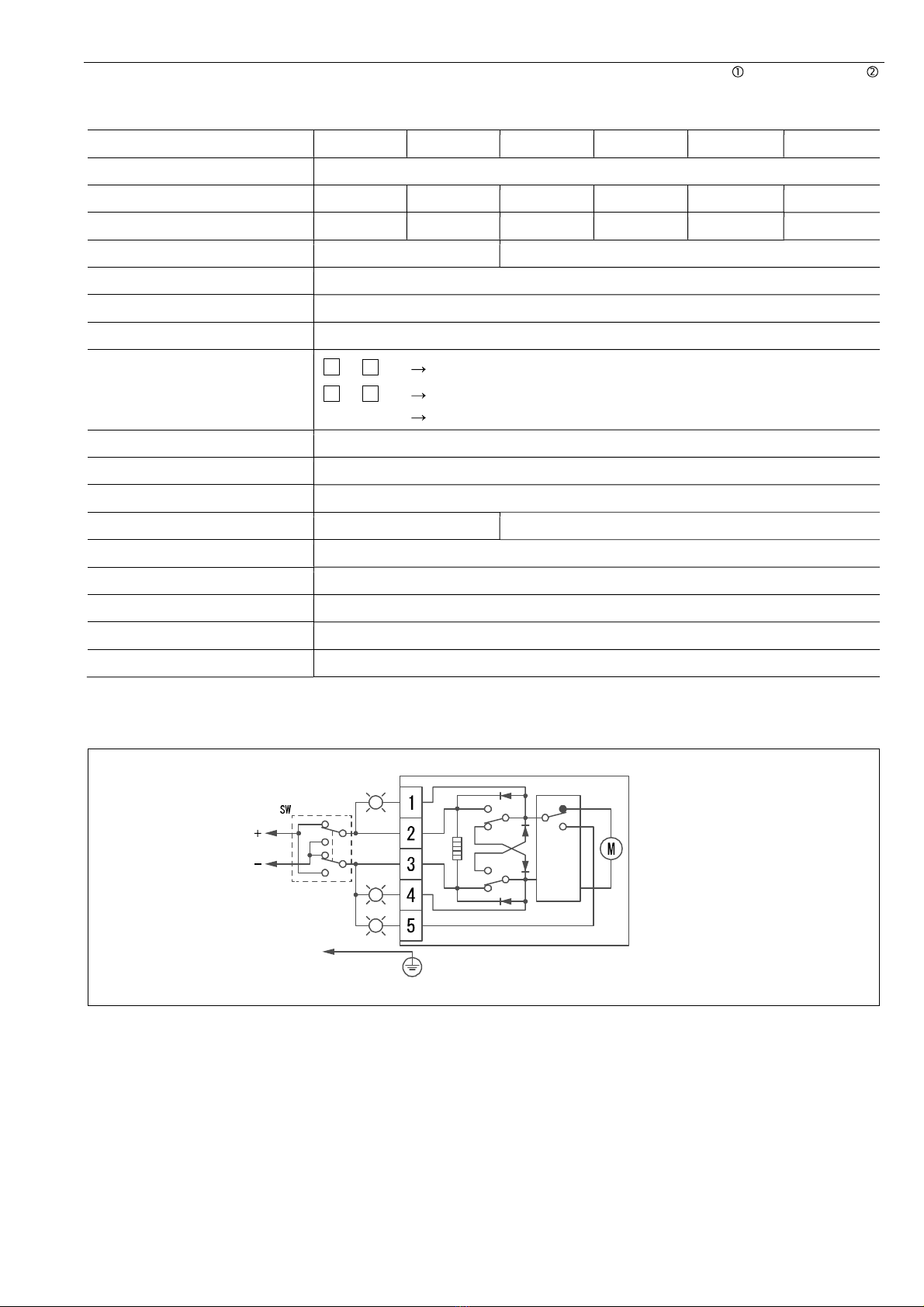
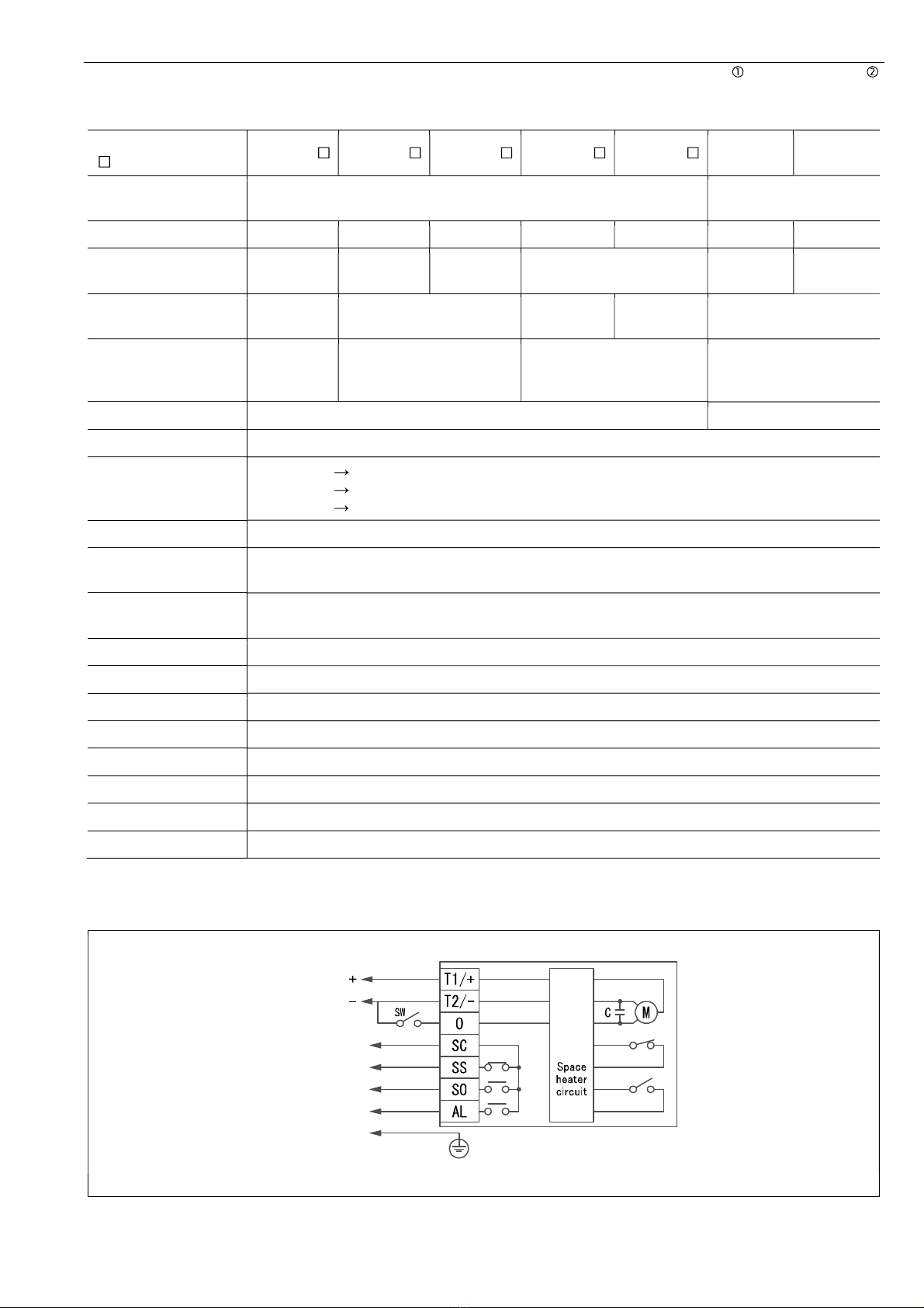
Method of operation a-contactinput type, with built-in relay
Operation SW is OFF SHUT (R3 SW is ON)
SW is ON OPEN (R4 SW is ON)
Over torque R5 SW is ON
Input signal current 10 mA 100 V AC / 6.5 mA 200 V AC / 38 mA 24 V DC
(Leakage current in SW: less than 1 mA) *O terminal input: Photo coupler
Output signal rating Resistance load 0.5 A 125 V AC / 1 A 24 V DC Micro load 1 mA 5 V DC
Alarm signal Output when the motor protection circuit operates by the overload.
(it returns by power supply OFF or reverse operating signal)
Duty cycle 20 % 15 min. (When ambient temperature is over 50 ºC, 10 % 15 min.)
Ambient temperature -20 to 55 °C
Space heater 0.8 W
Manual operation Manual over-ride with clutch. (Direct operation / 06K: Operation by manual shaft.)
Enclosure Equivalent to IP65 (IEC 60529)
Housing material Aluminum alloy diecast (acrylic resin baking finish)
Wire connection Terminal Block: M3, Ground terminal: M3
Conduct port 2-G1/2 Attachments: Cable gland (for 6 to 12 mm cable), plug.
WIRING
Note) Leakage current in SW: less than 1 mA.
SH
(T)ACpoweronly
R3
R4
R5
SH
R1
R2
S.LS O.LS
com.
Voltage
100/110V AC
200/220V AC
24V DC
SHUT signal
OPEN signal
Alarm signal
Ground terminal(M3)