OSVBF225-EN
9/11
INSTALLATION, OPERATION & MAINTENANCE INSTRUCTIONS
HANDLING & STORAGE
HANDLING
Proper care in handling the valve should be taken to
prevent damage. Do not drop or throw it.
STORAGE
Store the valve in the protected area from dust,
moisture, and direct sunlight. If possible, should be
kept in the original packaging.
CHECKING
• Check the product code, power supply, and voltage
before installation.
• Make sure that the bolts are not loose.
• The DIP switch should be set up before the power is
turned on. Do not touch unnecessary switches.
INSTALLATION
PRECAUTIONS
• Flush the pipeline carefully before installing the
valve. Foreign particles, such as sand or pieces of
welding electrode, will damage the ball and seats.
• For valves with specified flow direction (V), check the
arrows on the product before piping.
• When the flow path is subjected to a high pressure
from arrow, it may leak slightly to the low pressure
port. (L2)
PIPING FLANGES
• Gasket should be selected appropriately to suit the
fluid, pressure and temperature.
Use spring washer to prevent from decreasing
surface pressure gasket when the temperature
change happens frequently.
• Tighten all bolts using crossover method to load the
joint evenly.
ENVIRONMENT
• Do not install in place where corrosive gas is present
or where vibration is heavy (0.5 G or more).
• When radiant heat causes the surface temperature
of the control unit to exceed 55 °C, provide an
appropriate shielding plate.
• If there is a possibility that the fluid and drive part
freeze, please take measures to prevent freezing.
POSITIONING
Should be positioned through 90° upward from
horizontal. Provide space around the product to
allow manual operation, inspection and replacement
work.
Maintenance space for upper part of actuator.
AEX (120 / 360 / 700) More than 105 mm
AEX (02K / 06K) More than 120 mm
OTHER NOTES
Until the wiring is completed there must be no
condensation or flooding in the interior of the
actuator, after piping. Protective caps on the cable
gland are not waterproof.
TIGHTEN THE GLAND NUTS
• Check that there is no leakage from the gland
packing.
• If it leakage, tighten gland nuts by alternately.
Do not over-tighten the gland nuts.
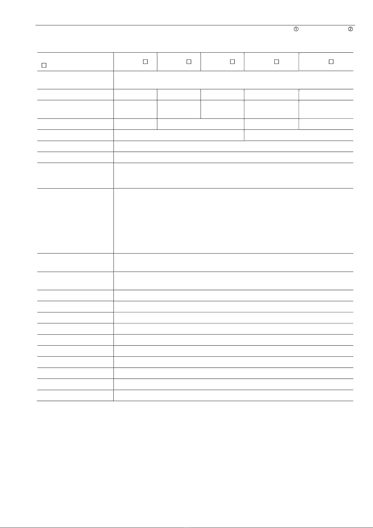
Recommended torques
Valve size [mm] Torque
[Nm]
BF V L2
015
020
025
025 020
025 6
040
050
040
050
040
050 9
065
080
100
065
080
100
065
080
100
15
125
150
125
150 - 25
- 200 - 30
WIRING
PRECAUTIONS
• Remove the actuator cover before wiring.
• Two G1/2 electrical connections are provided with a
cable gland and plug. Usable cable size is 6 to 12
mm.
• When using a flexible tube, dew condensation may
occur inside the actuator due to respiration from the
inside of the tube and malfunction may result. Seal
the flexible tube connector part with a sealant.
• Sealants that affect the electrical contacts should not
be used inside the electric actuator.
• If long distance wiring or low voltage operation,
check that terminal voltage is in the proper range.
• Input signal circuit is non-isolated.
Do not connect DC (minus) wire to other DC (minus)
common.
CONNECTION
• Do not wiring outdoors on a rainy day.
• Check the power supply and voltage.
Connect the signal as shown in the wiring diagram.
Do not connect unnecessarily terminal.
• Check whether the MODE change DIP SW on a
circuit board substrate is set up correctly.
• When wiring, if wiring of a signal is mistaken, it will
not operate correctly. Contact us when you use two
valve or more by one controller or indicator.
• Actuator should be electrically grounded.
Use the terminal marked ( ) inside the actuator.
Gland nut
Gland plate Stem