VSpeak Electronic switch 20A (opto) User manual

Electronic switch 20A (opto) www.VSpeak-modell.de Page 1/4
Electronic switch 20A (opto)
Content Page
1Description..................................................................................................................................................1
2Installation..................................................................................................................................................2
2.1 Elektrical Installation...................................................................................................................................2
2.2 Mechanical Installation................................................................................................................................2
3Programming..............................................................................................................................................2
3.1 ON-Threshold/ON-Range............................................................................................................................2
3.2 Checking/Changing the operation mode......................................................................................................2
3.3 Changing the pulse width in Mode 2 ...........................................................................................................2
4LED-Display...............................................................................................................................................3
4.1 internal green LED.......................................................................................................................................3
4.2 external blue LED........................................................................................................................................3
5Technical data.............................................................................................................................................3
6Accessories..................................................................................................................................................4
6.1 external blue LED........................................................................................................................................4
6.2 Magnet .........................................................................................................................................................4
6.3 KAVAN Universal Glow-Plug Connector...................................................................................................4
7EG-Declaration of Conformity .................................................................................................................4
8Instructions for disposal............................................................................................................................4
1Description
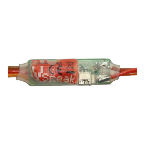
The electronic switch (opto) is a small device without any moving parts. Therefore it is resistant to any kind of
impact and vibration. It is especially designed for the rough environment in RC-models. Due to the flexible
programmability it can be used for virtually any application like lights, ignition, pyrotechnics, but also for
functional models like tanks, trucks and many more. It is also possible to control more than one electronic switches
with only 1 channel of your radio.
The output can be used in 2 different modes, either „ON“ or pulsed (PWM) with adjustable pulse width. This is e.g.
useful for directly driving glow plugs or other loads without the need for a separate driver.
The electronic switch (opto) is controlled by a microcontroller and galvanically isolated via an optocoupler from
the load side. You can use a separate power source for the load. The electronic switch (opto) switches the positive
line.
The electronic switch is connected to a servo terminal on the receiver.
It can be easily programmed with a magnet. The operating mode, switch state, programming and malfunctions are
signalled with the integrated green LED.
The optional "external blue LED" can be connected to the electronic switch (opto) and should be placed
somewhere visible from outside of the model. The external LED is only lit when the switch status is "ON" and the
external power source is connected. This helps when looking for faults (dead battery, damaged cable, ...).
If the servo-signal is missing for more than 2.5 seconds, the load is switched OFF and cannot be activated unless
the receiver is power cycled. Also, the green LED will blink every half second.
Using Mode1 the electronic switch can be used as ignition switch for gas engines. Using Mode2 the electronic
switch can be used to directly drive glow plugs for methanol motors without the need for a voltage regulator. If
there is no free channel on the receiver left, the electronic switch (opto) can be used on the same channel with the
throttle servo. The "ON" range has to be programmed for the whole range of the throttle stick. To disable the
ignition, use throttle cut or throttle trim to move the throttle signal below. You should consider programming the
failsafe settings to cut the ignition.
Make sure you perform a range check with activated electronic switch before flying your model !

Electronic switch 20A (opto) www.VSpeak-modell.de Page 2/4
2Installation
2.1 Elektrical Installation
2.2 Mechanical Installation
The electronic switch (opto) should be mounted using double sided foam tape or hot glue on the inside of the outer
hull of the model, so you can program it using the magnet.
Notice: The electronic switch (opto) is programmed by a magnet. Mare sure you place it away from strong
magnetic fields, like brushless motors or canopy mounting magnets.
3Programming
Make sure the radio and receiver are powered and the electronic switch (opto) is connected to the right channel.
Also make sure the channel is set to the desired "ON" position.
3.1 ON-Threshold/ON-Range
Hold a magnet to the magnet-sensor (white dot). If the magnet is near enough, the green LED starts blinking. To
enter programming mode, keep the magnet near the sensor for 4 seconds. The green LED will start flickering, the
switch is turned "ON". If you only want to program a fixed switch position, you are done now. If you want to
program a "ON"-range, then move the corresponding stick on the radio to the upper and lower limit. The electronic
switch (opto) will memorize these positions and switch "ON", as long the signal is within this range. Remove the
magnet when you are done.
3.2 Checking/Changing the operation mode
After switching on the electronic switch and after detecting a valid servo signal, the operation mode is always
shown: 1 pulse of the LED means permanent operation, 2 pulses means PWM mode.
You can change the operation mode if you keep the magnet for at least 4 seconds near the magnet-sensor after
setting the switch threshold (first the operation mode is shown with the blinking LED) by moving the proportional
control/stick/knob on the radio for this channel.
Remark: If you change the operation mode, the previously changed switch threshold will NOT be stored.
3.3 Changing the pulse width in Mode 2
If you have activated Mode 2 in the previous step and the magnet is still near the magnet-sensor, you can adjust the
pulse with after 4 seconds. This is shown with a fast flickering LED. Use the proportional control (stick/slider or
pot) to adjust the pulse width. By doing so you can easily adjust the glow temperature of your glow plug. If you
cannot adjust the pulse width high enough, you can repeat this step.
To avoid damages the PWM is set to minimul value when shipped.
Caution: - The voltage of the battery is NOT monitored by the electronic switch!
- The pulse width is NOT adjusted according to the battery voltage, so make sure you adjust it with a
fully charged battery to avoid damages to your glow plug.
- If you change your battery to a higher voltage one, you have to readjust the pulse width to avoid
damages to your glow plug.
- With well adjusted Motors, where the glow plug is only needed for the motor start, you can use the
receiver battery instead a separate glow battery. In this case there can be a feedback from the PWM to
the receiver/servos which can also affect the radio's range. Make sure that the glowing function IS NOT
ACTIVATED DURING FLIGHT !
The benefits from using the receiver battery for glowing:
Weight and space saving (you need no glow battery)
No need for a separate cable to the glow box
RX cable
socket for the external blue LED
green LED
magnet-sensor (white dot)
external battery
load
red…….external battery (positive)
yellow/red…witched positive line
black…..........load (negative)

Electronic switch 20A (opto) www.VSpeak-modell.de Page 3/4
4LED-Display
4.1 internal green LED
OFF: Switch is OFF
ON: Switch is ON
Blinking: Magnet near Sensor, switch status is kept on previous state
-or-
Fault, no servo signal for more than 2.5 seconds, switch is "OFF"
Flickering: Programming mode (switch is "ON")
Single-Pulse: Mode1 „ON“
Double-Pulse: Mode2 „PWM-Mode“
4.2 external blue LED
OFF: Load is switched "OFF", no connection to the load battery
ON: Load is switched "ON", power from load battery
5Technical data
Servo input
3,0 … max 15V
Switching voltage
3,0 … max 20V (3…13 Cells NiCd/NiMh, 1 to 4 Cells LiPo/LiFe)
Switch current
max 20 A
Power consumption
(control part, powered by the RX)
ON: about 13 mA
OFF: about. 4 mA
Power consumption
(switching part, powered by the
external battery)
ON: about 8 mA/ 2mA with / without external blue LED
OFF: ~0 mA (max 0,001 mA)
Mode 2, Pulsefrequency
~510 Hz
Size
30 x 9 x 8 mm (PCB)
Weight
6 g (incl. cable)
Connectors
RX cable (0,14 mm²)
red: Battery-positive: 15cm Silicone cable (1,0 mm²)
black: Battery-negative:15cm Silicone cable (0,25 mm²)
yellow/red: switched line: 15cm Silicone cable (1,0 mm²)
2-pin socket for the external blue LED
The "ON" range can be programmed completely free.

Electronic switch 20A (opto) www.VSpeak-modell.de Page 4/4
6Accessories
The following accessories are not included:
6.1 external blue LED 6.2 Magnet
6.3 KAVAN Universal Glow-Plug Connector
7EG-Declaration of Conformity
Manufacturer
VSpeak-Modellbau (Volker Weigt)
Priestewitz
We hereby declare that the product
Electronc switch 20A (opto)
complies with the following European directives:
2004/108/EC EMC Directive
2006/95/EC Low Voltage Directive (LVD)
2011/65/EC Restriction of Hazardous Substances (RoHS)
The presumption of conformity is taken by applying the following harmonized standards:
EN60065 Audio-, video- and similar electronic aparatus - Safety requirements
EN60332 Tests on electric and optical fibre cables under fire conditions
EN60950 Information technology equipment - Safety
EN61000-6-1 Electromagnetic compatibility (EMC)
EN61000-6-3
EN55022 Information technology equipment - Radio disturbance characteristics
Priestewitz, 2014/07/01 .........................................................
Signature
Volker Weigt
Managing Director
8Instructions for disposal
Equipment marked with the symbol should not be disposed of within household waste.
Cable length about 23 cm
about. 8 cm
Table of contents
Other VSpeak Control Unit manuals