— 4 —
V SERIES
INSTALLATION
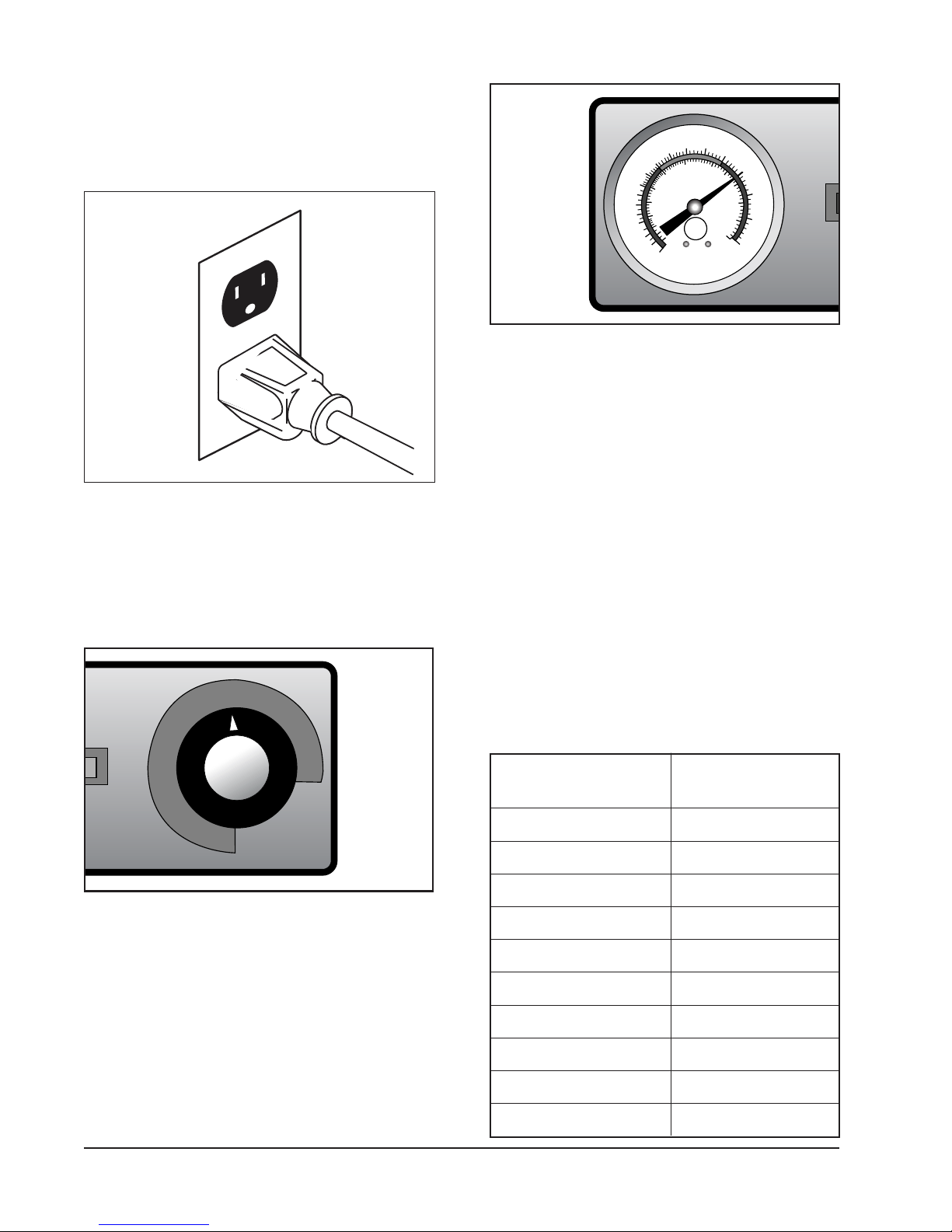
Before installing, verify the electrical service
agrees with the specifications on the rating
plate located on the lower rear of the cart. If
the electrical service does not agree with the
rating plate, do not proceed with installation.
Contact your dealer or local Vulcan-Hart
service technician immediately.
Fig. 2
UNPACKING
The APPLIANCE was inspected before leaving
the factory. The transportation company
assumes full responsibility for safe delivery
upon acceptance of the shipment.
Immediately after unpacking, check for
possible shipping damage. If the APPLIANCE
is damaged, save packing material and
contact the carrier within 15 days of delivery.
Check the delivery documentation for damage
reporting contacts and time limits.
Carefully unpack and place in a work-
accessible area as near the installation
position as possible.
1. Open the door and carefully remove any
packaging materials and the retaining
straps that hold the wire plate racks
(VB) or tray slides and tray slide upright
side supports (VBP/VHP).
2. Remove all scratch protective film from
the cabinet.
3. On banquet carts, lift the plate racks
into position on the side brackets.
4. On food holding and transport cabinets,
remove cardboard element cover
protector from cabinet bottom.
Remove adjustable tray slides from box.
Remove the tray slide supports and
install them in the cabinet.
a. Hook the openings in the flat flange of
the support over two vertical carriage
bolts on the interior of the cabinet.
b. Make sure all flanges on the four
supports face the door opening.
Install tray slides in the cabinet.
Make sure the hook on the end of the
tray slide is up.
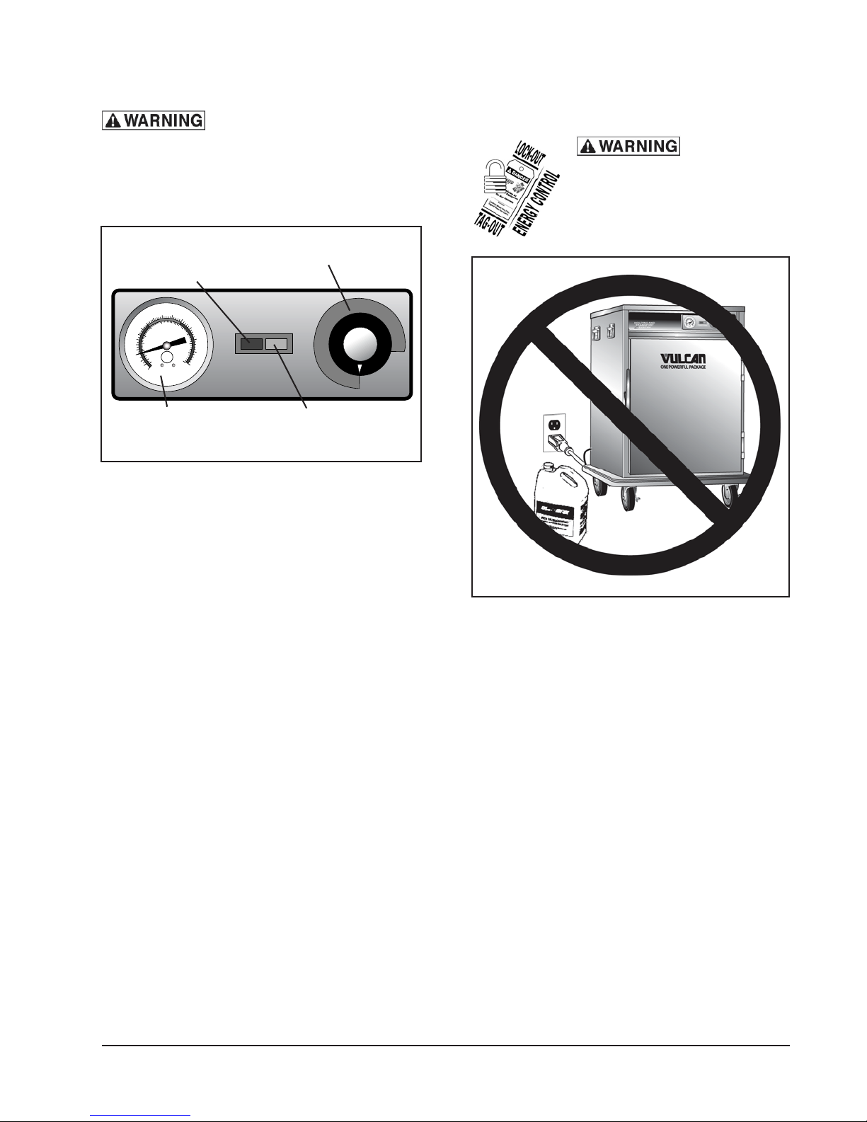
LOCATION
For efficient cabinet operation, choose a
location that will provide easy loading and
unloading without interfering with the final
assembly of food orders.
Fig. 3
The installation location must allow adequate
clearances for servicing and proper operation.
1
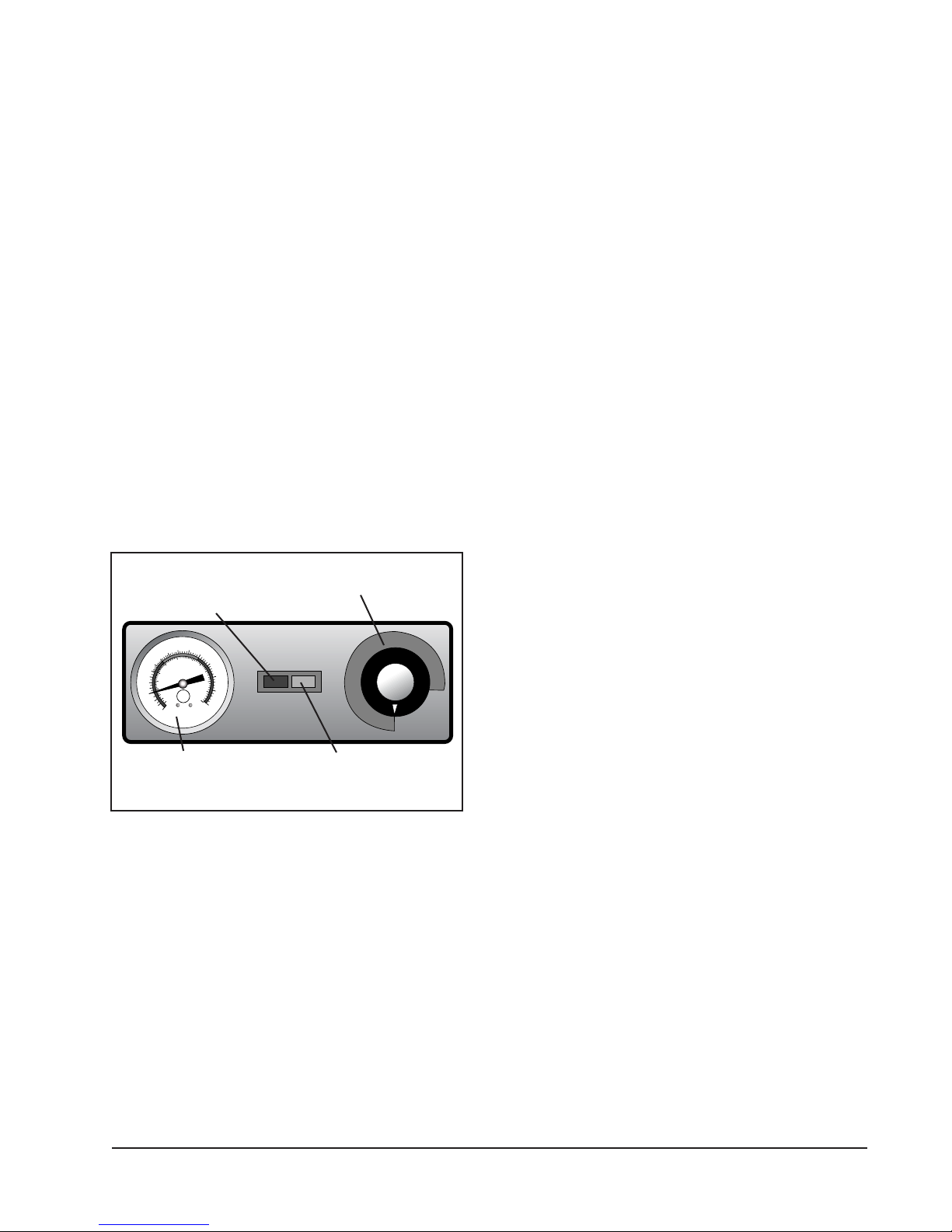
POWER/HEAT
2
OFF
345678
9
10
NSF
®
°F
20
60
80
100
120
140
150
160
170
180
190
200
210
220
0
20
40
50
60
7080
90
100
105
°C
HOLDINGAND
TRANSPORT
SYSTEM
Leave adequate clearance
for ease of loading and unloading.