Vutec VU-PRO VT14X User manual

Installation Instructions
VU-PRO
Models VT14X, VT18X, VT22X
VIDEO PROJECTOR LIFT
VIDEO PROJECTION SCREENS
VUTEC
03/04/99 PL-MAN_ORG

PROJECTOR LIFT
LARGE LCD, DLP, D-ILA, CRT SERIES PROJECTORS
MODELS VT14X, VT18X & VT22X
MODEL VT14X MODEL VT18X MODEL VT22X
Max. projector space (HWL) 14 1/2 x 22 1/2 x 27 18 1/2 x 25 1/2 x 35 22 1/2 x 31 1/2 x 43
Overall dimensions (HWL) 22 x 29 x 31 26 x 32 x 39 30 x 38 x 47
Min. space above finished ceiling 22 26 30
Ceiling closure panel (WL) 29 x 31 32 x 39 38 x 47
Downward travel(in/cm) 14/35,6 18/45,7 22/55,9
Travel time (approx.) 7 sec. 10 sec. 13 sec.
Max. lifting capacity (lbs/kg) 180/82 240/109 300/136
Net weight (lbs/kg) 80/36 100/45 130/59
Ampere/Watt(120VAC) 1.5/170 1.8/210 2.1/250
VT14X VT18X VT22X
MW 23 26 32
ML 28 36 44
CW 29 32 38
CL 31 39 47
SP 22 26 30

1
OVERVIEW
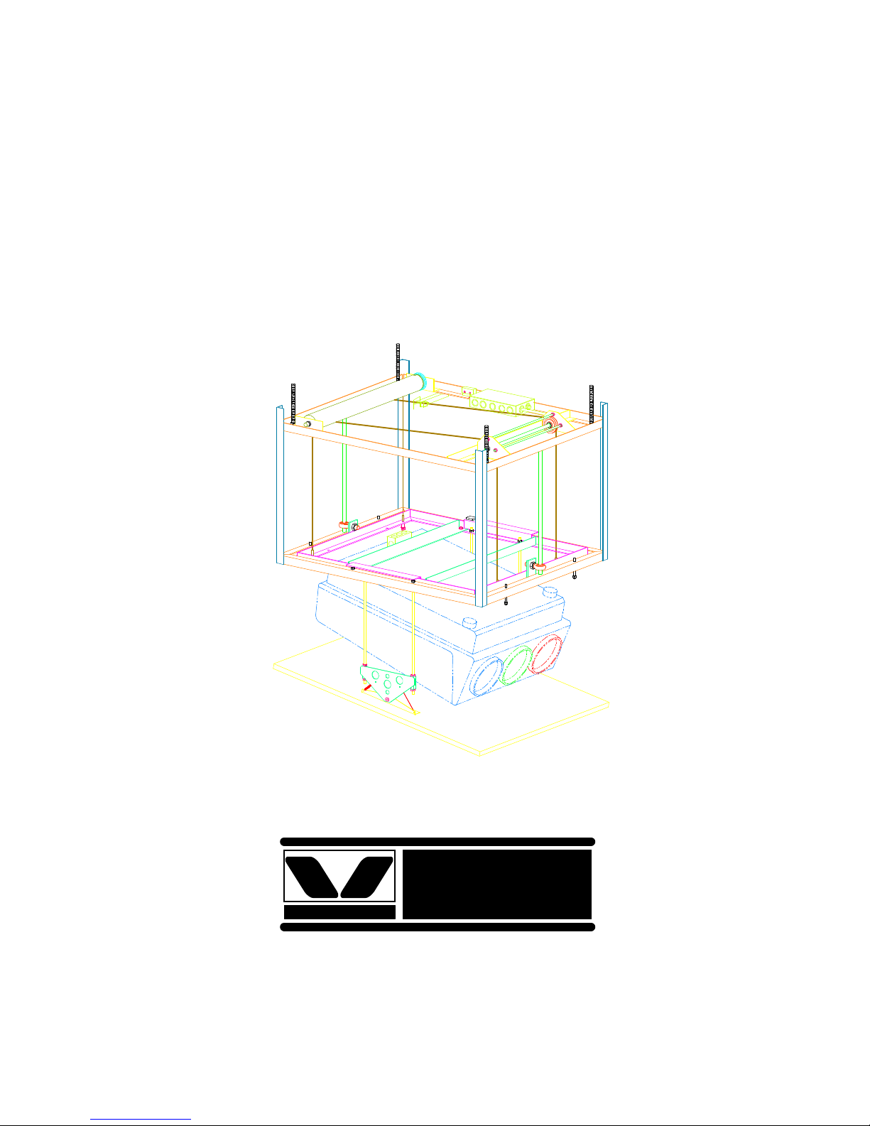
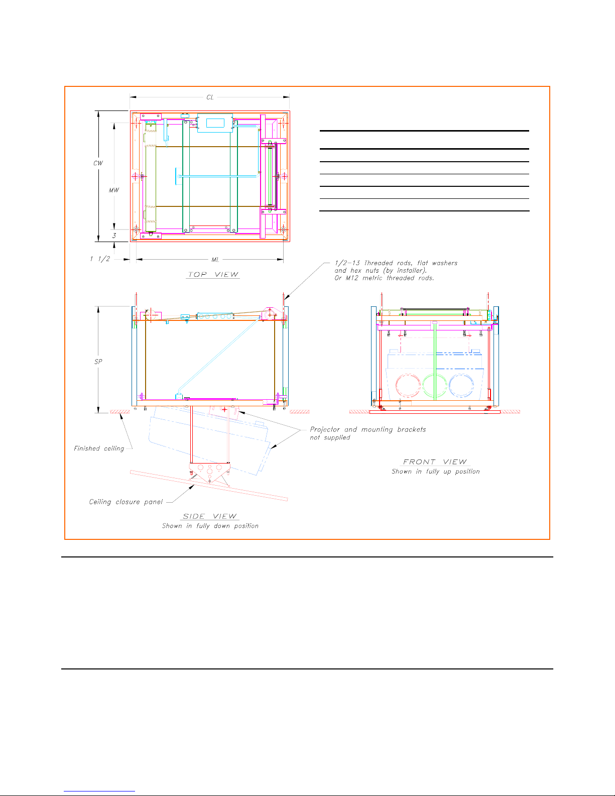
The most common method of installing the VU-PRO projector lift is to suspend it on four, 1/2-
13 threaded rods, from any convenient overhead support. Vertical alignment and leveling is
accomplished by individual adjustment of the threaded rods. Horizontal stability may be
accomplished by guy wires or from contact with the framing around the opening for the projector
lift. The overhead support can often be adapted from the existing building structure, or, if
necessary, constructed specially for this purpose. However constructed, the support must be
capable of sustaining the following loads:
Model VT14X 80 lbs. + Projector Weight
Model VT18X 100 lbs. + Projector Weight
Model VT22X 120 lbs. + Projector Weight
It is important to remember that this will be a continuous dead weight for the life of the
installation. The solidness, or rigidity, of the support structure needs to be sufficient to support
this load without a slow movement, or relaxation, over time.
Following are the primary steps involved in the planning and completion of a standard
installation.
MECHANICAL INSTALLATION
A - DETERMINE PROJECTOR LOCATION
1. Location of the ceiling opening. How critical this location has to be will depend on the
projector being used.
Projectors equipped with a zoom lens can focus the intended image size through a range
of distances of several feet variation. For this reason the exact distance, projector to
screen surface, need only be held within the particular focus range specified by the
projector manufacturer for the intended screen size.
For projectors with a fixed focal length lens, the exact distance, projector lens to screen
surface, becomes much more critical. The projector will have a fairly short range of fine
focus adjustment, and the final installation must end up with the projector located within
this range. It is important to know what this range is, so that you will have a feel for how
critical the projector location actually is.
Focus distance, or throw distance, is usually specified by the manufacturer as the
horizontal distance, face of the projector lens to the face of the screen. Sometimes it is
expressed as the downward angled, straight-line distance, from the center of the lens to
the center of the projected image. Since these two measures are different, it is important
to know which you are working with, before laying out the job.

2
2. Once the exact location of the ceiling opening is established, refer to the data sheet at
the end of this manual and ensure that there is sufficient headroom above the opening to
receive the projector lift.
Inspect the existing structure above this spot to see if any modifications are required for
adequate support of the finished system. If a support framework needs to be built,
observe the physical arrangement of the projector lift, and be sure to leave satisfactory
access for inspection, maintenance and electrical hookup.
B - INSTALLING THE PROJECTOR IN THE LIFT UNIT
1. Depending on job conditions and the projector being used, it may be easier to remove
the ceiling closure panel from the lift unit, before installing the projector. To do so, turn
the projector lift upside down and let it rest on the floor - supported by the four corner
angles. Remove the four plastic caps covered the mounting screws, loosen the screws
and lift off the panel.
2. Referring to Figure 1 - the projector is
mounted and suspended from two
projector mount angles. Temporarily
remove the duplex receptacle mounted
to one angle, and remove the angles.
3. Locate and mount the projector
mounting bracket (not supplied) to the
two angles. Use the longer legs of the
angles for mounting. Re-hang the
angles, with the projector mounting
bracket, to the traveling platform.
FIGURE 1
4. Attach the projector to the projector mounting bracket. Center the projector by moving
the angles back and forth. When optimum location is found, drill four clearance holes
for the 1/4-20 nut and bolt, and secure the projector mount angles to the traveling
platform.
5. Reinstall the duplex receptacle to the rear projector mount angle. Be sure to tighten all
nuts and bolts.
6. Depending on the total weight of the lift unit and projector combined, you may want to
remove the projector from the lift, before actually installing the lift. This may mean,
however, that you will then need to re-install the projector under more difficult
conditions.

3
C - HANGING THE PROJECTOR LIFT
The VU-PRO projector lift is designed to mount recess into the ceiling, supported by four 1/2
inch threaded rods (not provided) - see the data sheet at the end of this manual for dimensions.
Dimension “SP” on the data sheet is based upon the 3/4” thick ceiling closure panel shipped with
the unit - if the final thickness of actual panel is 1” or more, the difference between 3/4” and the
actual thickness should be added to dimension “SP”.
Each threaded rod should be secured by a pair of nuts as shown in Figure 2. The nuts should be
adjusted such that all four rods are sharing the load roughly equally, then the pairs tightened
against each other to securely lock the connection.
Determine the desired location for the projector lift, and install per the following guidelines:
1. Unit should be level, with weight
shared roughly equally by the four
threaded rods.
2. It is recommended that the supporting
structure be able to carry at least four
times the total weight of the unit,
including projector weight.
3. Access to control box - refer to figure
4 - should be provided in case service
is required. Optionally, the control
box can be rewired and relocated to a
different location. Refer to the wiring
diagram at the end of this manual.
4. Attach a safety cable to the outer frame of the unit, and secure the other end to any nearby
attachment point that will be strong enough to catch the lift if it should fall.
5. Do not use this unit to support other fixtures, such as lighting, fans, etc.
FIGURE 2
This manual suits for next models
2
Table of contents
Other Vutec Projector Accessories manuals