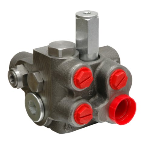
WABCO 973 002 User manual
Other WABCO Control Unit manuals
WABCO
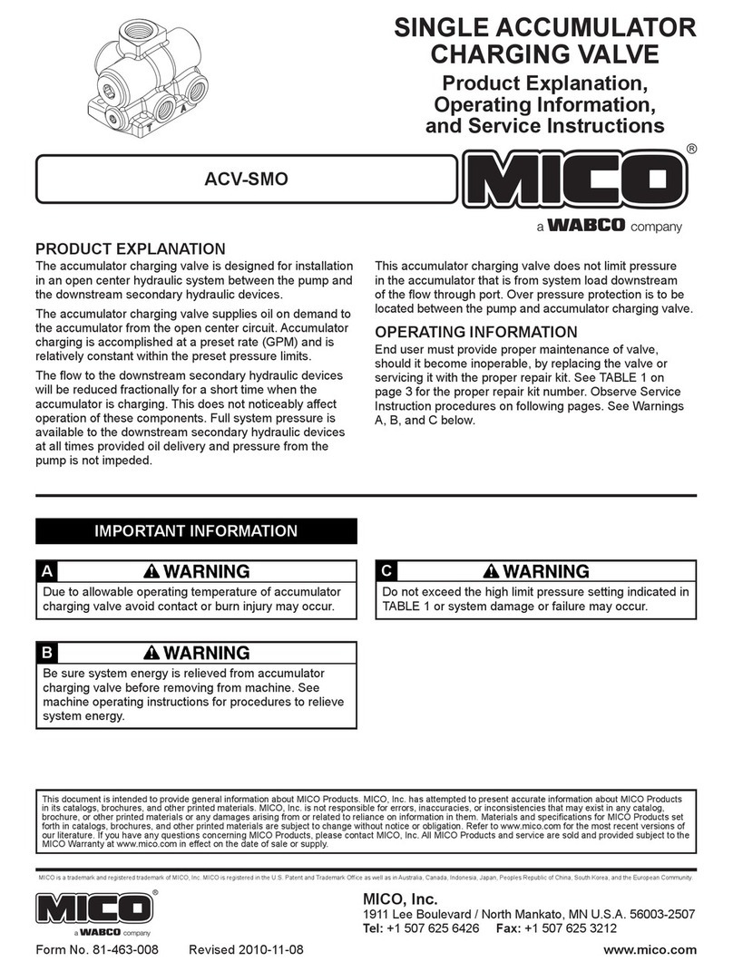
WABCO MICO ACV-SMO Operating instructions

WABCO
WABCO MICO 20-100-597 Operating instructions
WABCO
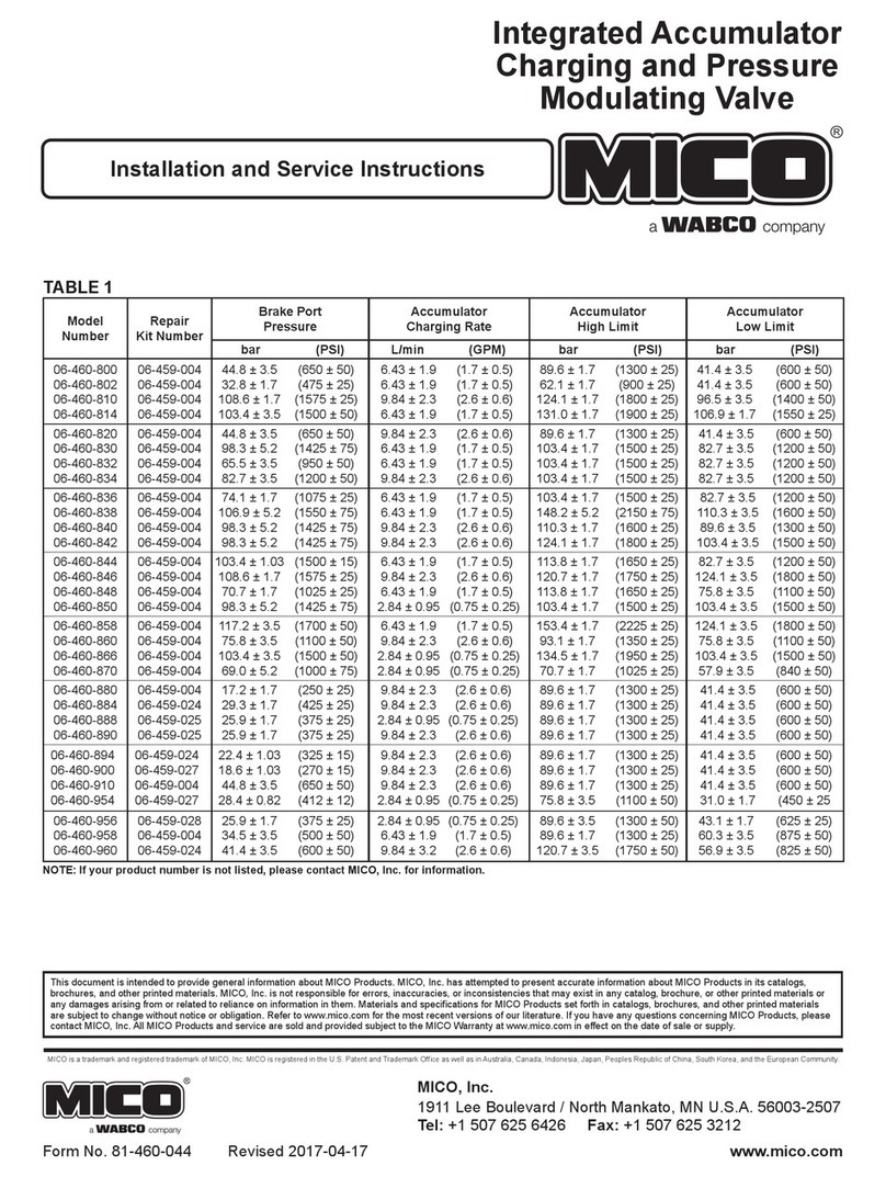
WABCO MICO 06-460-800 Quick guide
WABCO
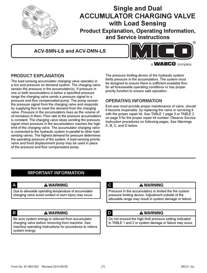
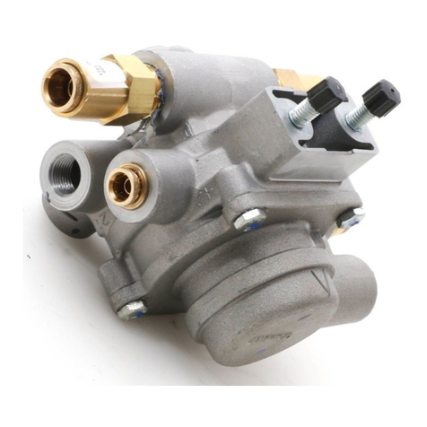
WABCO MICO ACV-DMN-LS Operating instructions
WABCO
WABCO IR-2 Service manual

WABCO
WABCO MICO ACV-SMO Operating instructions
WABCO
WABCO ABDX Operating instructions
WABCO
WABCO 461 307 User manual

WABCO
WABCO 461 317 User manual

WABCO
WABCO TP0223 Service manual
Popular Control Unit manuals by other brands

Festo
Festo Compact Performance CP-FB6-E Brief description

Elo TouchSystems
Elo TouchSystems DMS-SA19P-EXTME Quick installation guide

JS Automation
JS Automation MPC3034A user manual

JAUDT
JAUDT SW GII 6406 Series Translation of the original operating instructions

Spektrum
Spektrum Air Module System manual

BOC Edwards
BOC Edwards Q Series instruction manual

KHADAS
KHADAS BT Magic quick start

Etherma
Etherma eNEXHO-IL Assembly and operating instructions

PMFoundations
PMFoundations Attenuverter Assembly guide

GEA
GEA VARIVENT Operating instruction

Walther Systemtechnik
Walther Systemtechnik VMS-05 Assembly instructions

Altronix
Altronix LINQ8PD Installation and programming manual
