manuals.online logo
Brands
  1. Home
  2. •
  3. Brands
  4. •
  5. WABCO
  6. •
  7. Control Unit
  8. •
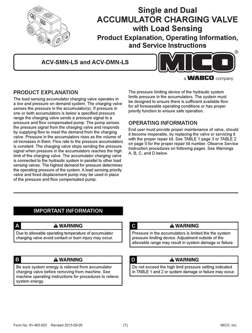
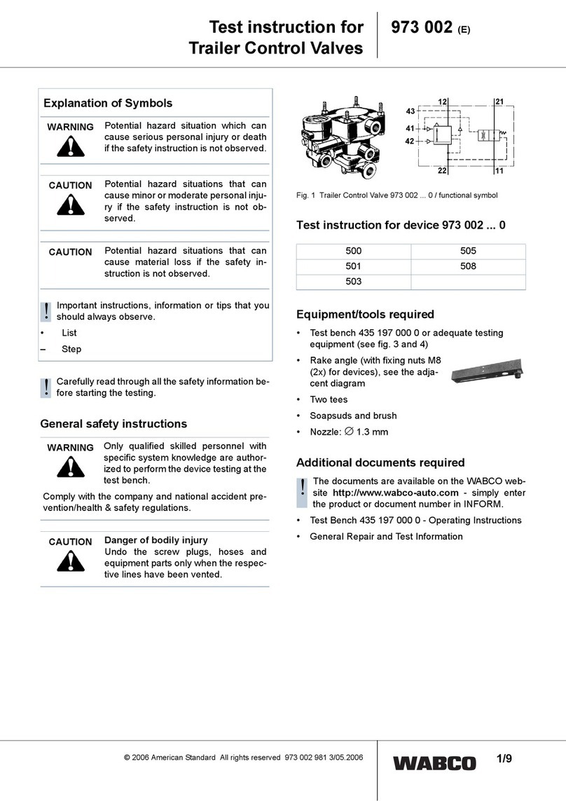
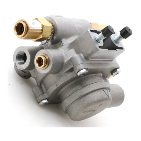
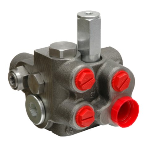
  9. WABCO MICO 06-460-800 Quick guide

WABCO MICO 06-460-800 Quick guide

Integrated Accumulator
Charging and Pressure
Modulating Valve
Installation and Service Instructions
TABLE 1
Model
Number
Repair
Kit Number
Brake Port
Pressure
Accumulator
Charging Rate
Accumulator
High Limit
Accumulator
Low Limit
bar (PSI) L/min (GPM) bar (PSI) bar (PSI)
06-460-800
06-460-802
06-460-810
06-460-814
06-459-004
06-459-004
06-459-004
06-459-004
44.8 ± 3.5 (650 ± 50)
32.8 ± 1.7 (475 ± 25)
108.6 ± 1.7 (1575 ± 25)
103.4 ± 3.5 (1500 ± 50)
6.43 ± 1.9 (1.7 ± 0.5)
6.43 ± 1.9 (1.7 ± 0.5)
9.84 ± 2.3 (2.6 ± 0.6)
6.43 ± 1.9 (1.7 ± 0.5)
89.6 ± 1.7 (1300 ± 25)
62.1 ± 1.7 (900 ± 25)
124.1 ± 1.7 (1800 ± 25)
131.0 ± 1.7 (1900 ± 25)
41.4 ± 3.5 (600 ± 50)
41.4 ± 3.5 (600 ± 50)
96.5 ± 3.5 (1400 ± 50)
106.9 ± 1.7 (1550 ± 25)
06-460-820
06-460-830
06-460-832
06-460-834
06-459-004
06-459-004
06-459-004
06-459-004
44.8 ± 3.5 (650 ± 50)
98.3 ± 5.2 (1425 ± 75)
65.5 ± 3.5 (950 ± 50)
82.7 ± 3.5 (1200 ± 50)
9.84 ± 2.3 (2.6 ± 0.6)
6.43 ± 1.9 (1.7 ± 0.5)
6.43 ± 1.9 (1.7 ± 0.5)
9.84 ± 2.3 (2.6 ± 0.6)
89.6 ± 1.7 (1300 ± 25)
103.4 ± 1.7 (1500 ± 25)
103.4 ± 1.7 (1500 ± 25)
103.4 ± 1.7 (1500 ± 25)
41.4 ± 3.5 (600 ± 50)
82.7 ± 3.5 (1200 ± 50)
82.7 ± 3.5 (1200 ± 50)
82.7 ± 3.5 (1200 ± 50)
06-460-836
06-460-838
06-460-840
06-460-842
06-459-004
06-459-004
06-459-004
06-459-004
74.1 ± 1.7 (1075 ± 25)
106.9 ± 5.2 (1550 ± 75)
98.3 ± 5.2 (1425 ± 75)
98.3 ± 5.2 (1425 ± 75)
6.43 ± 1.9 (1.7 ± 0.5)
6.43 ± 1.9 (1.7 ± 0.5)
9.84 ± 2.3 (2.6 ± 0.6)
9.84 ± 2.3 (2.6 ± 0.6)
103.4 ± 1.7 (1500 ± 25)
148.2 ± 5.2 (2150 ± 75)
110.3 ± 1.7 (1600 ± 25)
124.1 ± 1.7 (1800 ± 25)
82.7 ± 3.5 (1200 ± 50)
110.3 ± 3.5 (1600 ± 50)
89.6 ± 3.5 (1300 ± 50)
103.4 ± 3.5 (1500 ± 50)
06-460-844
06-460-846
06-460-848
06-460-850
06-459-004
06-459-004
06-459-004
06-459-004
103.4 ± 1.03 (1500 ± 15)
108.6 ± 1.7 (1575 ± 25)
70.7 ± 1.7 (1025 ± 25)
98.3 ± 5.2 (1425 ± 75)
6.43 ± 1.9 (1.7 ± 0.5)
9.84 ± 2.3 (2.6 ± 0.6)
6.43 ± 1.9 (1.7 ± 0.5)
2.84 ± 0.95 (0.75 ± 0.25)
113.8 ± 1.7 (1650 ± 25)
120.7 ± 1.7 (1750 ± 25)
113.8 ± 1.7 (1650 ± 25)
103.4 ± 1.7 (1500 ± 25)
82.7 ± 3.5 (1200 ± 50)
124.1 ± 3.5 (1800 ± 50)
75.8 ± 3.5 (1100 ± 50)
103.4 ± 3.5 (1500 ± 50)
06-460-858
06-460-860
06-460-866
06-460-870
06-459-004
06-459-004
06-459-004
06-459-004
117.2 ± 3.5 (1700 ± 50)
75.8 ± 3.5 (1100 ± 50)
103.4 ± 3.5 (1500 ± 50)
69.0 ± 5.2 (1000 ± 75)
6.43 ± 1.9 (1.7 ± 0.5)
9.84 ± 2.3 (2.6 ± 0.6)
2.84 ± 0.95 (0.75 ± 0.25)
2.84 ± 0.95 (0.75 ± 0.25)
153.4 ± 1.7 (2225 ± 25)
93.1 ± 1.7 (1350 ± 25)
134.5 ± 1.7 (1950 ± 25)
70.7 ± 1.7 (1025 ± 25)
124.1 ± 3.5 (1800 ± 50)
75.8 ± 3.5 (1100 ± 50)
103.4 ± 3.5 (1500 ± 50)
57.9 ± 3.5 (840 ± 50)
06-460-880
06-460-884
06-460-888
06-460-890
06-459-004
06-459-024
06-459-025
06-459-025
17.2 ± 1.7 (250 ± 25)
29.3 ± 1.7 (425 ± 25)
25.9 ± 1.7 (375 ± 25)
25.9 ± 1.7 (375 ± 25)
9.84 ± 2.3 (2.6 ± 0.6)
9.84 ± 2.3 (2.6 ± 0.6)
2.84 ± 0.95 (0.75 ± 0.25)
9.84 ± 2.3 (2.6 ± 0.6)
89.6 ± 1.7 (1300 ± 25)
89.6 ± 1.7 (1300 ± 25)
89.6 ± 1.7 (1300 ± 25)
89.6 ± 1.7 (1300 ± 25)
41.4 ± 3.5 (600 ± 50)
41.4 ± 3.5 (600 ± 50)
41.4 ± 3.5 (600 ± 50)
41.4 ± 3.5 (600 ± 50)
06-460-894
06-460-900
06-460-910
06-460-954
06-459-024
06-459-027
06-459-004
06-459-027
22.4 ± 1.03 (325 ± 15)
18.6 ± 1.03 (270 ± 15)
44.8 ± 3.5 (650 ± 50)
28.4 ± 0.82 (412 ± 12)
9.84 ± 2.3 (2.6 ± 0.6)
9.84 ± 2.3 (2.6 ± 0.6)
9.84 ± 2.3 (2.6 ± 0.6)
2.84 ± 0.95 (0.75 ± 0.25)
89.6 ± 1.7 (1300 ± 25)
89.6 ± 1.7 (1300 ± 25)
89.6 ± 1.7 (1300 ± 25)
75.8 ± 3.5 (1100 ± 50)
41.4 ± 3.5 (600 ± 50)
41.4 ± 3.5 (600 ± 50)
41.4 ± 3.5 (600 ± 50)
31.0 ± 1.7 (450 ± 25
06-460-956
06-460-958
06-460-960
06-459-028
06-459-004
06-459-024
25.9 ± 1.7 (375 ± 25)
34.5 ± 3.5 (500 ± 50)
41.4 ± 3.5 (600 ± 50)
2.84 ± 0.95 (0.75 ± 0.25)
6.43 ± 1.9 (1.7 ± 0.5)
9.84 ± 3.2 (2.6 ± 0.6)
89.6 ± 3.5 (1300 ± 50)
89.6 ± 1.7 (1300 ± 25)
120.7 ± 3.5 (1750 ± 50)
43.1 ± 1.7 (625 ± 25)
60.3 ± 3.5 (875 ± 50)
56.9 ± 3.5 (825 ± 50)
NOTE: If your product number is not listed, please contact MICO, Inc. for information.
This document is intended to provide general information about MICO Products. MICO, Inc. has attempted to present accurate information about MICO Products in its catalogs,
brochures, and other printed materials. MICO, Inc. is not responsible for errors, inaccuracies, or inconsistencies that may exist in any catalog, brochure, or other printed materials or
any damages arising from or related to reliance on information in them. Materials and specications for MICO Products set forth in catalogs, brochures, and other printed materials
are subject to change without notice or obligation. Refer to www.mico.com for the most recent versions of our literature. If you have any questions concerning MICO Products, please
contact MICO, Inc. All MICO Products and service are sold and provided subject to the MICO Warranty at www.mico.com in effect on the date of sale or supply.
MICO is a trademark and registered trademark of MICO, Inc. MICO is registered in the U.S. Patent and Trademark Ofce as well as in Australia, Canada, Indonesia, Japan, Peoples Republic of China, South Korea, and the European Community.
MICO, Inc.
1911 Lee Boulevard / North Mankato, MN U.S.A. 56003-2507
Tel: +1 507 625 6426 Fax: +1 507 625 3212
Form No. 81-460-044 Revised 2017-04-17 www.mico.com
MICO, Inc. (2) Form No. 81-460-044 Revised 2017-04-17
DISASSEMBLY
(Refer to Figure 1)
1. Remove ring (22) and boot (21) from control section housing (10).
2. Remove piston (20), shim(s) (19), spring (18) and spring (17)
from control section housing (10). Note the number of shim(s)
removed for reassembly purposes. NOTE: Not all models use
spring (17).
3. Remove o-ring (16). Depress plunger (13) and remove retaining
ring (15).
4. Remove washer (14), plunger (13), and spring (11) from housing
(10). Remove cup (12) from plunger (13). Note direction of cup (12).
5. Remove plug (1) from control section housing (10).
6. Remove washer (5), spring (6) and guide (7) from housing bore.
7. Remove o-ring (2), cup (4), and back-up ring (3) from plug (1).
8. Remove valve assembly (8) from housing bore.
9. Remove o-ring (9) from valve assembly (8).
10. Remove plug (24) from control section housing (10). Remove
o-ring (25) from plug (24).
11. Remove nylon pin (23) from plug (24) using a drive pin punch.
Be careful not to damage threads.
12. Remove spring (26), seat (27) and ball (28) from housing bore.
13. Remove plug (37) from control section housing (10). Remove
o-ring (36) from plug (37).
14. Remove spring (35), stop (34), and ball (33) from housing bore.
15. Using a 6.35 mm (0.25 in) diameter wooden or plastic dowel,
carefully push insert (31) and spool (32) from housing bore.
NOTE: Be careful not to scratch or mar valve seats on
insert (31).
16. Remove spool (32) from insert (31). Remove o-rings (29 & 30)
from insert (31).
17. Earlier models: Loosen nut (38) on screw assembly (39) and
remove screw assembly (39) from housing (10). Remove o-ring
(40) from screw assembly (39). Remove spring (41), poppet or
ball (42), seat (43), o-ring (44), and washer (45) from housing (10).
Later models: Some later models use a directional spring (41).
Directional spring (41) is attached to screw assembly (39) by
means of the small diameter end of spring (41) being snapped
into a groove on the nose end of screw assembly (39). See
Figure 1a. Remove nut (38) and remove screw assembly (39)
from housing (10). Remove o-ring (40) from screw assembly (39)
from nut (38) side of screw assembly. Remove shim (63), spring
(41), steel ball (42), seat (43), o-ring (44) and washer (45) from
housing (10).
18. Remove lter (46) from housing (10).
19. Depress plug (48) and remove retaining ring (47) from charging
section housing (54).
20. Remove plug (48), spring (50), and stop (51) from housing bore.
Remove o-ring (49) from plug (48).
21. Remove spool (53) from housing bore. The spool can be guided
out of the charging section by reaching into either of the large ports.
22. Remove o-ring (52) from spool (53).
23. Depress plug (56) and remove retaining ring (57). Remove
plug (56) from housing bore.
24. Remove o-ring (55) from plug (56).
25. Remove three cap screws (58 & 62) and lock washers (59).
26. Separate control section housing (10) and charging section
housing (54).
27. Remove o-rings (60 & 61) from sections.
ASSEMBLY
(Refer to Figure 1)
LUBRICATE ALL RUBBER COMPONENTS FROM REPAIR KIT WITH
CLEAN TYPE FLUID USED IN THE SYSTEM.
1. Place new o-rings (60 & 61) in the proper grooves on charging
section housing (54).
2. Assemble control section housing (10) and charging section
housing (54) using three cap screws (58 & 62) and lock washers
(59). Torque cap screws 29.8-36.6 N·m (22-27 lb·ft).
3. Install new o-ring (55) on plug (56). Install plug in charging section
housing (54). Note direction of plug (56).
4. Install retaining ring (57) in housing (54) bore.
5. Install new o-ring (52) on spool (53). Insert spool in housing bore.
Be sure spool is all the way into bore so that the end of the spool
contacts the plug on opposite end. Note direction of spool.
6. Install spring (50) and stop (51) into housing (54).
7. Install new o-ring (49) on plug (48). Install plug (48) in housing
bore. Note direction of plug.
8. Install retaining ring (47) in charging section housing (54).
9. Install new lter (46) in control section housing (10).
10. Earlier Models: Install new o-ring (40) on screw assembly (39).
Install washer (45), new o-ring (44), seat (43), new plastic poppet
or existing steel poppet/steel ball (42), spring (41) and screw
assembly (39) into housing (10). Torque screw assembly (39)
24.4-29.8 N·m (18-22 lb·ft). Then install nut (38) on screw
assembly (39) and torque nut 43.4-51.5 N·m (32-38 lb·ft).
NOTE: Some models use a steel ball or steel poppet in place
of plastic poppet (42), reinstall steel ball or steel poppet.
Later models: Some later models use a directional spring
(41). Directional spring (41) is attached to screw assembly
(39) by means of the small diameter end of spring (41) being
snapped into a groove on the nose end of screw assembly
(39). If necessary, reattach the small diameter of spring (41)
into the groove on the nose end of screw assembly (39) using
a slight twisting motion. See Figure 1a. Install new o-ring (40)
on screw assembly (39) from nut (38) side of screw assembly.
Install washer (45), new o-ring (44), seat (43), steel ball (42), and
spring (41) in housing (10). Fully lubricate shim (63) with clean
system uid and install in housing (10) on end of seat (43). Install
screw assembly (39) in housing (10). Torque screw assembly (39)
24.4-29.8 N·m (18-22 lb·ft). Then install nut (38) on screw assembly
(39) and torque nut 43.4-51.5 N·m (32-38 lb·ft).
11. Install new o-rings (29 & 30) on insert (31).
12. Install spool (32) into insert (31). Note direction of insert (31)
and spool (32). Carefully install insert (31) into control section
housing (10).
13. Install ball (33) in housing bore.
14. Put a small amount of grease on end of spring (35) to hold stop
(34) in place. Install stop and spring in housing bore. Note direction
of stop and spring.
15. Install new o-ring (36) on plug (37) and install in housing bore.
Torque plug 54.2-67.8 N·m (40-50 lb·ft).
16. Position housings so plug (24) housing bore faces up. Drop ball
(28), seat (27), and spring (26) into housing.
17. Insert new nylon pin (23) into plug (24). Be sure nylon pin is
properly aligned and evenly driven into screw. Do not damage
threads.
18. Install new o-ring (25) on plug (24). Install plug (24) in housing
bore.
19. Install new o-ring (9) on valve assembly (8). Install valve assembly (8)
into control section housing (10). Note direction of valve assembly.
20. Insert new back-up ring (3) and new cup (4) in plug (1). Note order
of back-up ring and cup. Install new o-ring (2) on plug (1).
21. Install guide (7), spring (6), and washer (5) in plug (1).
22. Install plug assembly in control section housing (10). Torque
54.2-67.8 N·m (40-50 lb·ft).
23. Install new cup (12) and spring (11) on plunger (13). Install plunger
(13) in control section housing (10). Note direction of plunger.
24. Install washer (14) in housing bore.
25. Install retaining ring (15) in housing bore.
26. Install new o-ring (16), springs (17 & 18), shim(s) (19), and piston
(20) in housing bore. Be sure to install the same number of shim(s)
as removed during disassembly. NOTE: Not all models use
spring (17).
27. Install new boot (21) and new ring (22) on control section housing (10).
CHARGING VALVE ADJUSTMENT
The maximum accumulator pressure is adjusted by turning plug (24).
The high limit is raised by screwing plug into the body and lowered by
screwing plug out of the body.
- Attach a gauge to the accumulator port on the valve.
- Pump up the valve until a decisive click is heard,caused by the
shifting of the insert and spring.
- If the pressure is not as shown in the specications chart on
page1, at the time the click is heard, turn adjusting plug (24) to
alter the pressure to within specication.
Form No. 81-460-044 Revised 2017-04-17 (3) MICO, Inc.
FIGURE 1
Figure 1a
Items included in Repair Kit
Not used in all models
SERVICE DIAGNOSIS
(Refer to Figure 1)
BRAKE WILL NOT RELEASE
1. Inoperative valve assembly (8)
2. Piston (20), plunger (13), washer (14)
binding
INSUFFICIENT BRAKES
1. Broken pressure regulating spring (18)
2. Boot (21) damaged, allowing dirt to
accumulate under piston (20) ange
BRAKES WILL NOT RELEASE
COMPLETELY
1. Piston (20) sticking
2. Plunger (13) sticking
EXCESSIVE BRAKING
1. Too many shims (19) installed in valve
NO BRAKES
1. Plunger (13) or piston (20) stuck
2. Broken spring (18)
ACCUMULATOR CHARGING CYCLE
REPEATS FREQUENTLY WHEN BRAKES
ARE NOT BEING USED
1. Poppet (42) leaking
2. O-ring (44) leaking
3. Valve assembly (8) not seating
4. Pilot valve ball (33) leaking
5. Seals (4 & 9) leaking
ACCUMULATOR CHARGES FREQUENTLY
WHILE BRAKES ARE BEING HELD
1. Seal (12) worn
2. Seat on plunger (13) damaged
ACCUMULATOR STARTS TO CHARGE
BUT DOES NOT REACH HIGH LIMIT
1. O-rings (29 & 30) on pilot valve body
inoperative or damaged
2. O-ring (52) on charging valve spool (53)
has been damaged or worn
ACCUMULATOR CHARGING TIME
TOO LONG
1. Broken charging valve spring (50)
2. Charging valve spring (50) has taken a set
3. Dirt in lter (46)
4. Poppet (42) stuck, partially closed
ACCUMULATOR FAILS TO START
CHARGING
1. Broken pilot valve spring (26)
2. Broken charging valve spring (50)
3. Charging valve spool o-ring (52)
inoperative
4. Charging valve spool (53) stuck
5. Dirt in lter (46)
VERY RAPID CYCLING OF CHARGING
VALVE
1. Pilot valve (31 & 32) worn
MICO, Inc. (4) Form No. 81-460-044 Revised 2017-04-17
SERVICE CHECKS FOR HYDRAULIC SYSTEMS
BRAKES SLOW TO APPLY
1. No gas charge in accumulator
1. Check gas charge
2. Brakes not properly adjusted
2. Adjust brakes
3. Inoperative brakes
3. Check brakes
4. Hydraulic lines or ttings leaking
4. Check for leaks and repair
5. Pedal linkage out of adjustment
5. Adjust linkage
6. Inoperative automatic adjuster
(Goodrich Hi-torque Brakes only)
6. Check adjuster operation
7. Damaged hydraulic brake lines
7. Check lines for dents that restrict ow
of oil
BRAKES WILL NOT RELEASE
1. Pedal linkage out of adjustment or binding
1. Check for proper adjustment and
binding
2. Inoperative brakes
2. Check brakes
3. Inoperative automatic adjusters
3. Check operation of adjusters
4. Inoperative brake valve
4. Replace brake valve
INSUFFICIENT BRAKES
1. No oil or low oil level in tank
1. Check oil level in tank
2. Brakes not properly adjusted
2. Check brake adjustment
3. Oil or grease on brake lining
3. Clean or install new linings
4. Pedal linkage out of adjustment
4. Adjust linkage
5. Brake line damaged
5. Check lines and replace
6. Inoperative automatic adjuster
6. Check operation of adjusters
7. No gas charge in accumulator
7. Check gas charge
8. Inoperative brakes
8. Check brakes
9. Brake valve inoperative
9. Replace valve
BRAKES WILL NOT RELEASE
COMPLETELY
1. Brakes not properly adjusted
1. Adjust brakes
2. Inoperative brakes
2. Check brakes
2. Pedal linkage out of adjustment
3. Adjust pedal linkage
4. Inoperative wheel cylinders
4. Replace wheel cylinder
5. Inoperative automatic adjuster
5. Check operation of adjusters
6. Air in brakes (when automatic adjusters
used Goodrich Hi-torque Brakes only)
6. Bleed brakes
7. Inoperative brake valve
7. Replace brake valve
8. Back pressure on drain line too high
8. Remove restriction
EXCESSIVE BRAKING
1. Inoperative brakes
1. Check brakes
2. Inoperative brake valve
2. Replace brake valve
NO BRAKES
1. No oil in hydraulic system
1. Check oil level in tank
2. Pedal linkage out of adjustment
2. Adjust pedal linkage
3. Broken or damaged brake line
3. Check lines for breaks or damaged
condition
4. Brakes not properly adjusted
4. Adjust brakes
5. Inoperative system relief valve
5. Check pressure in pressure line to
valve
6. Worn pump
6. Check pressure in pressure line to
valve
7. Inoperative automatic adjuster
7. Check brake line pressure
8. Inoperative or worn brakes
8. Check brakes
9. Inoperative brake valve
9. Replace brake valve
ACCUMULATOR CHARGING CYCLE
REPEATS FREQUENTLY WHEN BRAKES
ARE NOT BEING USED
1. Leaking accumulator lines or ttings
1. Check lines and ttings for leaks and
correct
2. Accumulator gas charge too low
2. Check accumulator gas charge
3. Accumulator gas charge to high
3. Check accumulator gas charge
4. Inoperative brake valve
4. Replace valve
5. Line to accumulator plugged
5. Replace line
ACCUMULATOR STARTS TO CHARGE
BUT DOES NOT REACH HIGH LIMIT
1. No oil or low oil level in tank
1. Check oil level
2. Inoperative or worn pump (pump does not
deliver full ow or pressure)
2. Check pump pressure and ow
3. Inoperative system relief valve (valve
leaking or has low setting so full ow and
pressure are not available)
3. Check relief valve
4. Inoperative brake valve
4. Replace valve
ACCUMULATOR CHARGES FREQUENTLY
WHILE BRAKES ARE BEING HELD
1. Leaking brake lines or ttings
1. Check for leaks
2. Accumulator gas charge too low
2. Check accumulator gas charge
3. Accumulator gas charge too high
3. Check accumulator gas charge
4. Inoperative brake valve
4. Remove brake valve
INTERFERENCE WITH STEERING AT FULL
ENGINE THROTTLE BUT NOT AT IDLE
1. Inoperative brake valve
1. Replace brake valve
NO STEERING OR INADEQUATE STEER-
ING WHEN ACCUMULATOR IS CHARGING
BUT STEERING SATISFACTORY WHEN
ACCUMULATOR IS NOT CHARGING
1. Pump worn (not delivering full ow
or pressure)
1. Check pump pressure and ow
2. Relief valve inoperative (valve leaking so
that full ow and pressure not available)
2. Check relief valve
3. Inoperative brake valve
3. Replace brake valve
ACCUMULATOR CHARGING TIME
TOO LONG
1. No oil or low oil level in tank
1. Check oil level
2. Relief valve setting too low
2. Check valve setting
3. Pump worn or inoperative and not
delivering full ow or pressure
3. Check pump
4. Inoperative brake valve
4. Remove brake valve
ACCUMULATOR FAILS TO START
CHARGING
1. No oil or low oil level in tank
1. Check oil level
2. Worn or inoperative pump
2. Check pump pressure and ow
3. Inoperative relief valve
3. Check relief valve setting
4. Inoperative brake valve
4. Replace brake valve
VERY RAPID CYCLING OF CHARGING
VALVE
1. Accumulator gas charge too low
1. Check gas charge
2. Accumulator gas charge too high
2. Check gas charge
3. No gas charge in accumulator
3. Check gas charge
4. Inoperative brake valve
4. Replace brake valve
INTERFERENCE WITH OR NO STEERING
WITH ENGINE AT IDLE SPEED BUT
STEERING SATISFACTORY WITH ENGINE
AT FULL THROTTLE WITH THE ACCUMU-
LATOR CHARGING OR NOT CHARGING
1. Inoperative pump
1. Check pump pressure and delivery
2. Inoperative relief valve
2. Check relief valve setting
3. Inoperative steering system
3. Check steering system
BLEEDING PROCEDURE
Brake lines should be bled very carefully as soon as the valve is
installed in the machine. Air in the system will not allow the brakes to
properly release and may cause severe damage.
1. Start the engine and allow the accumulator to reach full charge.
Shut down the engine, then slowly apply and release the brakes,
waiting one minute between applications until brakes will not apply.
Repeat this step three times.
2. Operate the engine to maintain accumulator pressure to within
working limits throughout the bleeding procedure.
3. Open the bleeder screw at the wheel closest to the brake valve
and apply the brakes cautiously until all air is bled out of the line.
Then close the bleeder screw. Repeat this step at each wheel,
moving to the next closest wheel from the brake valve each time,
as follows: a. Left front b. Right front c. Right rear d. Left rear
4. Release brake pressure for at least 1 minute.
5. Apply the brakes, holding the pedal down for 10 seconds. Then
release the pressure for 1 minute. Repeat this step two more times.
6. Repeat step 3.
7. Check for system leaks and be sure of proper brake operation.

This manual suits for next models

30

Other WABCO Control Unit manuals

WABCO ABDX Operating instructions

WABCO

WABCO ABDX Operating instructions

WABCO MICO ACV-SMO Operating instructions

WABCO

WABCO MICO ACV-SMO Operating instructions

WABCO IR-2 Service manual

WABCO

WABCO IR-2 Service manual

WABCO 461 307 User manual

WABCO

WABCO 461 307 User manual

WABCO 973 002 User manual

WABCO

WABCO 973 002 User manual

WABCO MICO ACV-DMO-RV Operating instructions

WABCO

WABCO MICO ACV-DMO-RV Operating instructions

WABCO 461 317 User manual

WABCO

WABCO 461 317 User manual

WABCO TP0223 Service manual

WABCO

WABCO TP0223 Service manual

WABCO MICO 20-100-597 Operating instructions

WABCO

WABCO MICO 20-100-597 Operating instructions

WABCO MICO ACV-SMO Operating instructions

WABCO

WABCO MICO ACV-SMO Operating instructions

WABCO MICO ACV-DMN-LS Operating instructions

WABCO

WABCO MICO ACV-DMN-LS Operating instructions

Popular Control Unit manuals by other brands

Cinterion MC75i Hardware interface description

Cinterion

Cinterion MC75i Hardware interface description

schmersal SRB 202MSL operating instructions

schmersal

schmersal SRB 202MSL operating instructions

Emerson SEMPELL Installation and maintenance instructions

Emerson

Emerson SEMPELL Installation and maintenance instructions

Raychem TraceTek TTDM-2 Operation and maintenance manual

Raychem

Raychem TraceTek TTDM-2 Operation and maintenance manual

ADTRAN Quad E1/PRA user manual

ADTRAN

ADTRAN Quad E1/PRA user manual

Festo EXCM-10 quick start guide

Festo

Festo EXCM-10 quick start guide

Siemens RDM-MXL installation instructions

Siemens

Siemens RDM-MXL installation instructions

Festo CPV-D102 Elektronics manual

Festo

Festo CPV-D102 Elektronics manual

GE Multilin MM300 Communications guide

GE Multilin

GE Multilin MM300 Communications guide

GatesAir Intraplex DS-64NC Installation and operation manual

GatesAir

GatesAir Intraplex DS-64NC Installation and operation manual

YASKAWA U1000 Series Technical manual

YASKAWA

YASKAWA U1000 Series Technical manual

Blonder tongue DAP Series instruction manual

Blonder tongue

Blonder tongue DAP Series instruction manual

VersaLogic VersaFlap H.25 Manual instructions

VersaLogic

VersaLogic VersaFlap H.25 Manual instructions

Grundfos MP 204 Installation and operating instructions

Grundfos

Grundfos MP 204 Installation and operating instructions

Viega Easytop 2275.10 Instructions for use

Viega

Viega Easytop 2275.10 Instructions for use

Gira LEDOTRON operating instructions

Gira

Gira LEDOTRON operating instructions

Miele professional DOS K 85 Fitting instructions

Miele professional

Miele professional DOS K 85 Fitting instructions

TQ MBa6ULxL user manual

TQ

TQ MBa6ULxL user manual

manuals.online logo
manuals.online logoBrands
  • About & Mission
  • Contact us
  • Privacy Policy
  • Terms and Conditions

Copyright 2025 Manuals.Online. All Rights Reserved.