manuals.online logo
Brands
  1. Home
  2. •
  3. Brands
  4. •
  5. WABCO
  6. •
  7. Control Unit
  8. •
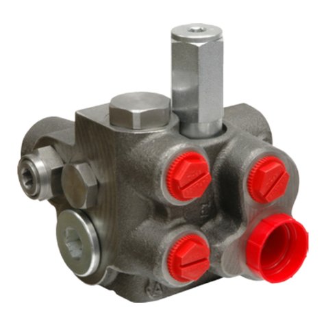
  9. WABCO MICO 20-100-597 Operating instructions

WABCO MICO 20-100-597 Operating instructions

This manual suits for next models

6

Other WABCO Control Unit manuals

WABCO MICO ACV-SMO Operating instructions

WABCO

WABCO MICO ACV-SMO Operating instructions

WABCO MICO ACV-DMN-LS Operating instructions

WABCO

WABCO MICO ACV-DMN-LS Operating instructions

WABCO 461 317 User manual

WABCO

WABCO 461 317 User manual

WABCO IR-2 Service manual

WABCO

WABCO IR-2 Service manual

WABCO MICO ACV-SMO Operating instructions

WABCO

WABCO MICO ACV-SMO Operating instructions

WABCO MICO 06-460-800 Quick guide

WABCO

WABCO MICO 06-460-800 Quick guide

WABCO MICO ACV-DMO-RV Operating instructions

WABCO

WABCO MICO ACV-DMO-RV Operating instructions

WABCO TP0223 Service manual

WABCO

WABCO TP0223 Service manual

WABCO ABDX Operating instructions

WABCO

WABCO ABDX Operating instructions

WABCO 973 002 User manual

WABCO

WABCO 973 002 User manual

WABCO 461 307 User manual

WABCO

WABCO 461 307 User manual

Popular Control Unit manuals by other brands

Seitz 14A80 user manual

Seitz

Seitz 14A80 user manual

Wilo RS485 Installation and operating instructions

Wilo

Wilo RS485 Installation and operating instructions

Becker CentralControl CC41 Commissioning Instruction

Becker

Becker CentralControl CC41 Commissioning Instruction

SICK CDB650 operating instructions

SICK

SICK CDB650 operating instructions

Panduit NetKey NKP5E88M Series installation instructions

Panduit

Panduit NetKey NKP5E88M Series installation instructions

MX Options Concentric Petite Fitting instructions

MX

MX Options Concentric Petite Fitting instructions

Clean Water Systems Fleck 2510 Installation & start?up guide

Clean Water Systems

Clean Water Systems Fleck 2510 Installation & start?up guide

Fairchild FSB44104A user guide

Fairchild

Fairchild FSB44104A user guide

LEGRAND Wattstopper LMIN-104 installation instructions

LEGRAND

LEGRAND Wattstopper LMIN-104 installation instructions

PMK ATT10BNCS instruction manual

PMK

PMK ATT10BNCS instruction manual

Tektronix TDS3FFT user manual

Tektronix

Tektronix TDS3FFT user manual

Woodward easYgen Technical manual

Woodward

Woodward easYgen Technical manual

Balluff BNI EIP-502-105-R015 user guide

Balluff

Balluff BNI EIP-502-105-R015 user guide

NXP Semiconductors TWR-LS1021A Getting started

NXP Semiconductors

NXP Semiconductors TWR-LS1021A Getting started

Advantech PCM-3117 Startup manual

Advantech

Advantech PCM-3117 Startup manual

Danfoss MCO 101 manual

Danfoss

Danfoss MCO 101 manual

Moons' Lin Engineering R701P user manual

Moons'

Moons' Lin Engineering R701P user manual

Aventics RV1 operating instructions

Aventics

Aventics RV1 operating instructions

manuals.online logo
manuals.online logoBrands
  • About & Mission
  • Contact us
  • Privacy Policy
  • Terms and Conditions

Copyright 2025 Manuals.Online. All Rights Reserved.

Priority/Charging
Valve
Service Instructions
TABLE 1 (Specications)
NOTE: If your product number is not listed, please contact MICO, Inc. for information.
Model
Number Type
Nominal
Accumulator
Charge Rate
69.0 bar @ (1000 PSI)
Accumulator
High Limit
20-100-597
20-100-605
20-100-606
20-100-639
20-100-640
20-100-641
20-100-758
Single
Single
Single
Single
Single
Single
Dual
L/min (GPM) bar (PSI)
Repair Kit
Number
06-400-177
06-400-177
06-400-177
06-400-177
06-400-177
06-400-177
06-400-250
7.57 ± 1.89 (2.00 ± 5)
7.57 ± 1.89 (2.00 ± 5)
4.28 ± 1.44 (1.13 ± .38)
3.6 ± .95 (.95 ± .25)
7.57 ± 1.89 (2.00 ± .5)
4.28 ± 1.44 (1.13 ± .38)
4.28 ± 1.44 (1.13 ± .38)
134.5 ± 3.5 (1950 ± 50)
193.0 ± 3.5 (2800 ± 50)
186.2 ± 3.5 (2700 ± 50)
134.5 ± 3.5 (1950 ± 50)
193.0 ± 3.5 (2800 ± 50)
186.2 ± 3.5 (2700 ± 50)
186.2 ± 3.5 (2700 ± 50)
Accumulator
Low Limit
bar (PSI)
74.1 ± 3.5 (1075 ± 50)
132.7 ± 3.5 (1925 ± 50)
141.3 ± 3.5 (2050 ± 50)
74.1 ± 3.5 (1075 ± 50)
132.7 ± 3.5 (1925 ± 50)
141.3 ± 3.5 (2050 ± 50)
141.3 ± 3.5 (2050 ± 50)
Relief
Valve Setting
bar (PSI)
168.9 ± 6.9 (2450 ± 100)
206.8 ± 3.5 (3000 ± 50)
203.4 ± 3.5 (2950 ± 50)
168.9 ± 6.9 (2450 ± 100)
206.8 ± 3.5 (3000 ± 50)
203.4 ± 3.5 (2950 ± 50)
203.4 ± 3.5 (2950 ± 50)
This document is intended to provide general information about MICO Products. MICO, Inc. has attempted to present accurate information about MICO Products in its catalogs,
brochures, and other printed materials. MICO, Inc. is not responsible for errors, inaccuracies, or inconsistencies that may exist in any catalog, brochure, or other printed materials or
any damages arising from or related to reliance on information in them. Materials and specications for MICO Products set forth in catalogs, brochures, and other printed materials
are subject to change without notice or obligation. Refer to www.mico.com for the most recent versions of our literature. If you have any questions concerning MICO Products, please
contact MICO, Inc. All MICO Products and service are sold and provided subject to the MICO Warranty at www.mico.com in effect on the date of sale or supply.
MICO is a trademark and registered trademark of MICO, Inc. MICO is registered in the U.S. Patent and Trademark Ofce as well as in Australia, Canada, Indonesia, Japan, Peoples Republic of China, South Korea, and the European Community.
MICO, Inc.
1911 Lee Boulevard / North Mankato, MN U.S.A. 56003-2507
Tel: +1 507 625 6426 Fax: +1 507 625 3212
Form No. 81-463-016 Revised 2003-06-03 www.mico.com
VALVE DISASSEMBLY
(Refer to Figure 1)
1. Remove valve assembly from machine by removing
cap screws (54 & 55). Remove o-rings (16 & 48).
Drain fluid from the valve.
2. From cavity 7 remove plug (1). Remove o-ring (2)
from plug (1).
3. From cavity 7 remove spring (3), poppets (4), sleeve
(6) and spring (8). NOTE: Be careful not to scratch
housing or sleeve bore. Not all models use spring
(3), poppets (4), sleeve (6) or spring (8).
4. Remove o-rings (5 & 7) from sleeve (6). NOTE: Not
all models use sleeve (6) or o-rings (5 & 7).
5. From cavity 6 remove end plug (9), spring (11), stop (12),
and ball (13) from housing (53). Remove o-ring (10)
from end plug (9). Note, spool (14) may or may not fall
out at this point.
6. Remove plug (23) from housing (53). Remove o-ring
(10) from plug (23).
7. BEFORE removing screw (21), ACCURATELY MEASURE
ITS DEPTH FROM THE END OF HOUSING BORE
and record for reassembly purposes. Remove screw (21)
from housing (53).
8. Remove spring (20), retainer (19), and 1/4 inch diameter
ball (18) from housing. Be sure to keep 1/4 inch diameter
ball (18), ball (13), and ball (44) separate from one
another.
9. Remove pin (22) from screw (21) using a drive pin
punch. Be careful not to damage the threads.
10. Using a 6.4 mm (1/4 in) wooden or plastic dowel,
carefully remove spool (14) and insert (15) from housing.
NOTE: Be careful not to scratch or mar valve seats
on spool (14).
11. Remove spool (14) from insert (15). Remove o-rings
(16 & 17) from insert (15).
12. From cavity 5 remove plug (24) from housing (53).
Remove o-ring (25) from plug (24).
13. Remove plug (30), spring (29), shim(s) (28), retainer
(27) and piston (26) from housing. Remove o-ring (25)
from plug (30). Note the number of shim(s) removed
for reassembly purposes.
14. From cavity 4 remove plug (31) from housing. Remove
move o-ring (32) from plug (31).
15. Remove plug (35), spring (34), and spool (33) from
housing (53). Remove o-ring (32) from plug (35).
NOTE: Earlier design used a two piece spool (33).
It is not necessary to disassemble these parts.
16. From cavity 3 remove plug (36) from housing (53).
Remove o-ring (32) from plug (36).
17. From cavity 2 remove plug (37), spring (38), and spool
(39) from housing (53). Remove o-ring (25) from plug (37).
18. Remove plug (40) from housing (53). Remove o-ring
(25) from plug (40).
19. From cavity 1 loosen nut (41) and remove screw (42),
spring (43), 7/16 inch diameter ball (44), seat (45),
o-ring (10), washer (46), and filter (47) from housing (53).
Remove o-ring (25) from screw (42).
20. From cavity 8 remove plug (50). Remove o-ring (51)
from plug (50).
21. From cavity 10 remove plug (52). Remove o-ring (51)
from plug (52).
VALVE ASSEMBLY
(Refer to Figure 1)
LUBRICATE ALL RUBBER COMPONENTS FROM REPAIR
KIT WITH CLEAN TYPE FLUID USED IN THE SYSTEM.
FOR EASE OF REASSEMBLY, SEPARATE AND MATCH
NEW O-RINGS TO OLD O-RINGS. USE TABLE 2 TO
IDENTIFY O-RING SIZES.
1. Thoroughly clean housing and all parts with clean
solvent and allow to dry before proceeding. Lubricate
all parts and housing bores with clean type fluid used
in the system.
2. Install new o-ring (51) on plug (52). Install plug (52)
in housing cavity 10 and torque 13.6-19.0 N·m
(10-14 lb·ft).
3. Install new o-ring (51) on plug (50). Install plug (50)
in housing cavity 8 and torque 13.6-19.0 N·m
(10-14 lb·ft).
4. Install new o-ring (25) on screw (42).
5. Install new filter (47), washer (46), new o-ring (10),
seat (45), 7/16 inch diameter ball (44), spring (43), and
screw (42) in cavity 1 of housing. Torque screw (42)
24.4-29.8 N·m (18-22 lb·ft).
6. Torque nut (41) 43.4-51.5 N·m (32-38 lb·ft).
7. Install new o-ring (25) on plug (40). Install plug (40)
in housing cavity 2 and torque 54.2-61.0 N·m (40-45 lb·ft).
8. Install new o-ring (25) on plug (37). Install spool (39),
spring (38), and plug (37) in housing cavity 2. Note the
direction of spool (39). Torque plug (37) 54.2-61.0 N·m
(40-45 lb·ft).
9. Install new o-ring (32) on plug (36). Install plug (36)
in housing cavity 3 and torque 27.1-32.5 N·m (20-24 lb·ft).
10. Install new o-ring (32) on plug (35). Carefully install
spool (33), spring (34), and plug (35) in housing cavity 4.
Note direction of spool (33). Torque plug (35)
27.1-32.5 N·m (20-24 lb·ft).
11. Install new o-ring (32) on plug (31). Install plug (31) in
housing cavity 4 and torque 27.1-32.5 N·m (20-24 lb·ft).
12. Install new o-ring (25) on plug (24). Install plug (24) in
in housing cavity 5 and torque plug (24) 54.2-61.0 N·m
(40-45 lb·ft).
13. Install new o-ring (25) on plug (30).
14. Install retainer (27), shim(s) (28), and spring (29) on the
stem of piston (26) and install into housing cavity 5.
Install plug (30) and torque 54.2-61.0 N·m (40-45 lb·ft).
Be sure to install the same number of shim(s) as were
removed during disassembly.
15. Install new o-rings (17 & 16) on insert (15).
16. Install spool (14) into insert (15). Note the direction of
spool (14) and insert (15). Carefully install insert (15)
into housing cavity 6.
17. Install new o-ring (10) on plug (9).
18. Insert ball (13), stop (12), spring (11), and plug (9) in
housing cavity 6. Torque plug (9) 47.5-54.2 Nּm
(35-40 lbּft)
19. Insert new pin (22) in screw (21). Be sure pin is aligned
properly and is evenly driven into screw. Do not damage
the threads.
20. Install 1/4 inch diameter ball (18), retainer (19) and
spring (20) into housing cavity 6.
NOTE
For reassembly purposes, arrange the parts in the order
in which they are removed while disassembling the
valve. While removing this valve from the vehicle o-rings
(16 & 48) may drop out of their pockets in housing (53).
Orifice (49) need not be removed from housing (53).
MICO, Inc. (2) Form No. 81-463-016 Revised 2003-06-03
Item
Number Quantity
2
4
5
7
10
16
17
22
25
32
47
48
51
1
2
1
1
3
2
1
1
5
3
1
2
2
Description
O-ring 1.005 O.D. x 0.799 I.S. x 0.103 Thick
Poppet
O-ring 0.816 O.D. x 0.676 I.D. x 0.070 Thick
O-ring 0.792 O.D. x 0.652 I.D. x 0.070 Thick
O-ring 0.818 O.D. x 0.644 I.D. x 0.087 Thick
O-ring 0.504 O.D. x 0.364 I.D. x 0.070 Thick
O-ring 0.441 O.D. x 0.301 I.D. x 0.070 Thick
Plug
O-ring 0.949 O.D. x 0.755 I.D. x 0.097 Thick
O-ring 0.624 O.D. x 0.468 I.D. x 0.078 Thick
Filter
O-ring 1.262 O.D. x 0.984 I.D. x 0.139 Thick
O-ring 0.495 O.D. x 0.351 I.D. x 0.072 Thick
21. Thread screw (21) into cavity 6 TO THE DEPTH
RECOREDED during disassembly.
22. Install new o-ring (10) on plug (23). Install plug (23)
into housing cavity 6 and torque 47.5-54.2 Nּm
(35-40 lbּft)
23. Install new o-rings (5 & 7) on sleeve (6). NOTE: Not all
models use sleeve (6) or o-rings (5 & 7).
24. Install spring (8), new poppets (4), sleeve (6), and
spring (3) in housing cavity 7. NOT: Not all models use
spring (8), poppets (4), sleeve (6), or spring (3).
25. Install new o-ring (2) on plug (1). Install plug (1) into
housing cavity 7 and torque 67.8-81.4 Nּm (50-60 lbּft).
26. Install valve on machine using new o-rings (16 & 48)
and cap screws (54 & 55).
CHARGE VALVE ADJUSTMENT
1. Properly reinstall the valve assembly. Connect the
plumbing according to machine specifications.
2. To adjust accumulator charge limits, start the machine
and wait 5-10 seconds for accumulator pressure to rise.
3. Adjust screw (21) with pump shut off to obtain specified
pressure limits (Table 1). Clockwise adjustment increases
pressure. Take a reading at the accumulator during this
adjustment.
RELIEF VALVE ADJUSTMENT
1. Turn steering wheel until it bottoms.
2. Slowly turn steering wheel until steering pressure
reaches specified pressure (Table 1). Take this reading
at steering input line. Steering pressure should not
exceed 210.3 bar (3000 PSI) during this adjustment.
3. Shut off pump and add or remove shim(s) (28) to obtain
the correct pressure.
FIGURE 1
Items included in Repair Kit
Not used in single accumulator charging valves
TABLE 2 (Items included in Repair Kit
MICO, Inc. (3) Form No. 81-463-016 Revised 2003-06-03