WABCO TPMS MANAGER User guide

TPMS MANAGER
SYSTEM DESCRIPTION

Table of contents

3
Table of contents
EN
Table of contents
1 General information ......................................................................................................................................... 4
2 Safety information............................................................................................................................................ 7
3 Components ..................................................................................................................................................... 9
4 Specications................................................................................................................................................. 10
5 Functions ........................................................................................................................................................ 11
6 Operating instructions................................................................................................................................... 12
6.1 Power ON/OFF ...................................................................12
6.2 Read/trigger sensor test ............................................................13
6.3 Triggering procedure ...............................................................15
6.4 Settings .........................................................................16
6.4.1 LF power ................................................................................................................................. 16
6.4.2 Units ........................................................................................................................................ 17
6.4.3 Buzzer ON............................................................................................................................... 17
6.4.4 Contrast................................................................................................................................... 17
6.4.5 Auto off.................................................................................................................................... 17
6.5 About ...........................................................................18
6.6 Language........................................................................18
6.7 Recent sensor data ................................................................19
7 Charging ......................................................................................................................................................... 20
7.1 Battery charging. . . . . . . . . . . . . . . . . . . . . . . . . . . . . . . . . . . . . . . . . . . . . . . . . . . . . . . . . . . . . . . . . . . 20
7.2 Battery replacement. . . . . . . . . . . . . . . . . . . . . . . . . . . . . . . . . . . . . . . . . . . . . . . . . . . . . . . . . . . . . . . . 20
8 Troubleshooting ............................................................................................................................................. 21
9 Tool update ..................................................................................................................................................... 21
9.1 WebTPM PC Suite installation........................................................21
9.2 USB internet option update ..........................................................21
10 Recycling ........................................................................................................................................................ 22
Edition 1
Version 1 (11.2017)
815 010 248 3 (en)
This publication is not subject to an updating service.
You will nd the current version at:
http://www.wabco.info/i/728

4
General information General information
EN 1 General information
Purpose of this document
This document is directed towards workshop employees and designed to assist in reading out faults
from the brake control unit.
Symbols used
WARNING Indicates a potentially hazardous situation
Failure to observe the safety instruction can result in
severe injuries or death.
–Follow the instructions in this warning to avoid
injury or death.
CAUTION Indicates a potentially hazardous situation
Failure to observe the safety instruction can result in
minor or moderately severe injuries.
–Follow the instructions in this warning to avoid
any injuries.
CAUTION Speciespossiblematerialdamage
Not observing the safety instruction can lead to
material damage.
–Follow the instructions in this warning to avoid
any material damage.
!Important information, instructions and/or tips that you must always observe.
Reference to information on the internet
– Action step
ÖConsequence of an action
List

5
General information
EN
Technical documents
– Open the WABCO INFORM online product catalogue:
http://inform.wabco-auto.com
– Search for documents by entering the document number.
The WABCO online product catalogue INFORM provides you with convenient access to the complete
technical documentation.
All documents are available in PDF format. Please contact your WABCO partner for printed versions.
Please note that the publications are not always available in all language versions.
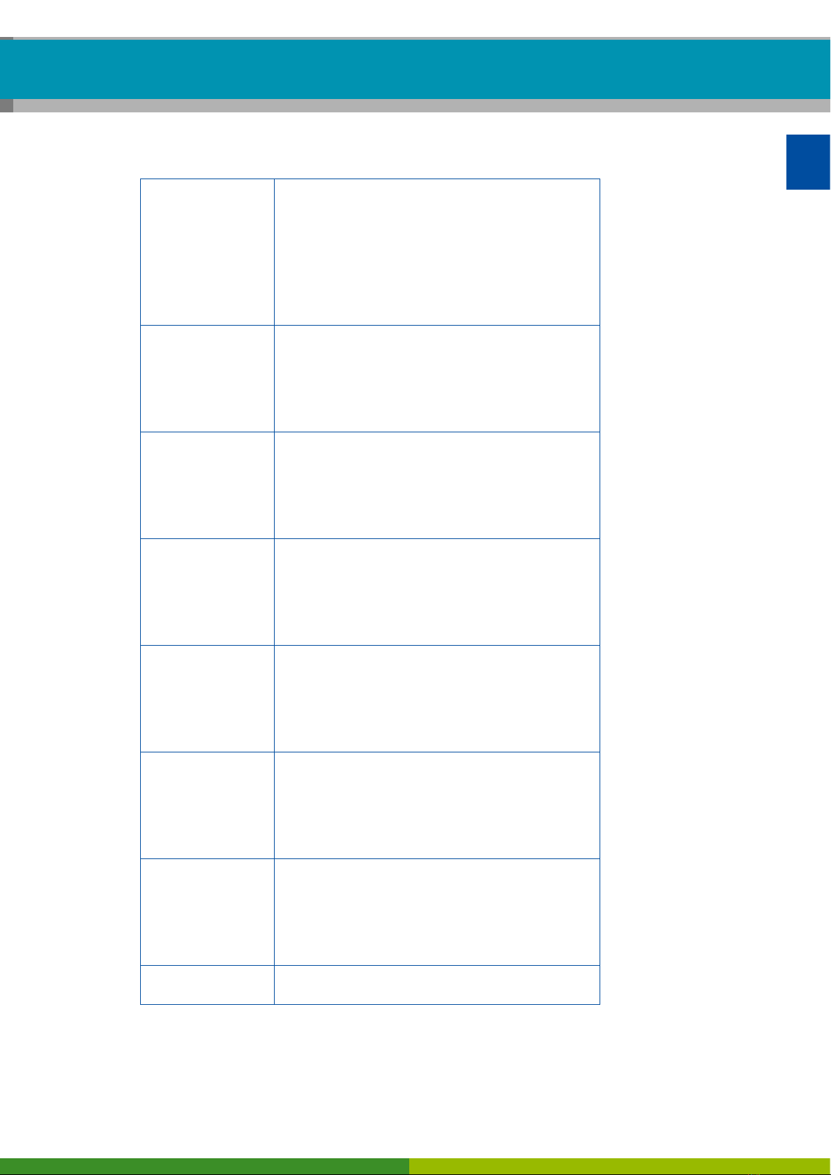
DOCUMENT TITLE DOCUMENT NUMBER
General Repair and Test Information 815 XX0 109 3
Diagnostic Product Overview 815 XX0 037 3
*Language code XX: 01 = English, 02 = German, 03 = French, 04 = Spanish, 05 = Italian, 06 = Dutch, 07 = Swedish,
08 = Russian, 09 = Polish, 10 = Croatian, 11 = Romanian, 12 = Hungarian, 13 = Portuguese (Portugal), 14 = Turkish,
15 = Czech, 16 = Chinese, 17 = Korean, 18 = Japanese, 19 = Hebrew, 20 = Greek, 21 = Arabic, 24 = Danish,
25 = Lithuanian, 26 = Norwegian, 27 = Slovenian, 28 = Finnish, 29 = Estonian, 30 = Latvian, 31 = Bulgarian, 32 = Slovakian,
34 = Portuguese (Brazil), 35 = Macedonian, 36 = Albanian, 97 = German/English 98 = multilingual, 99 = non-verbal
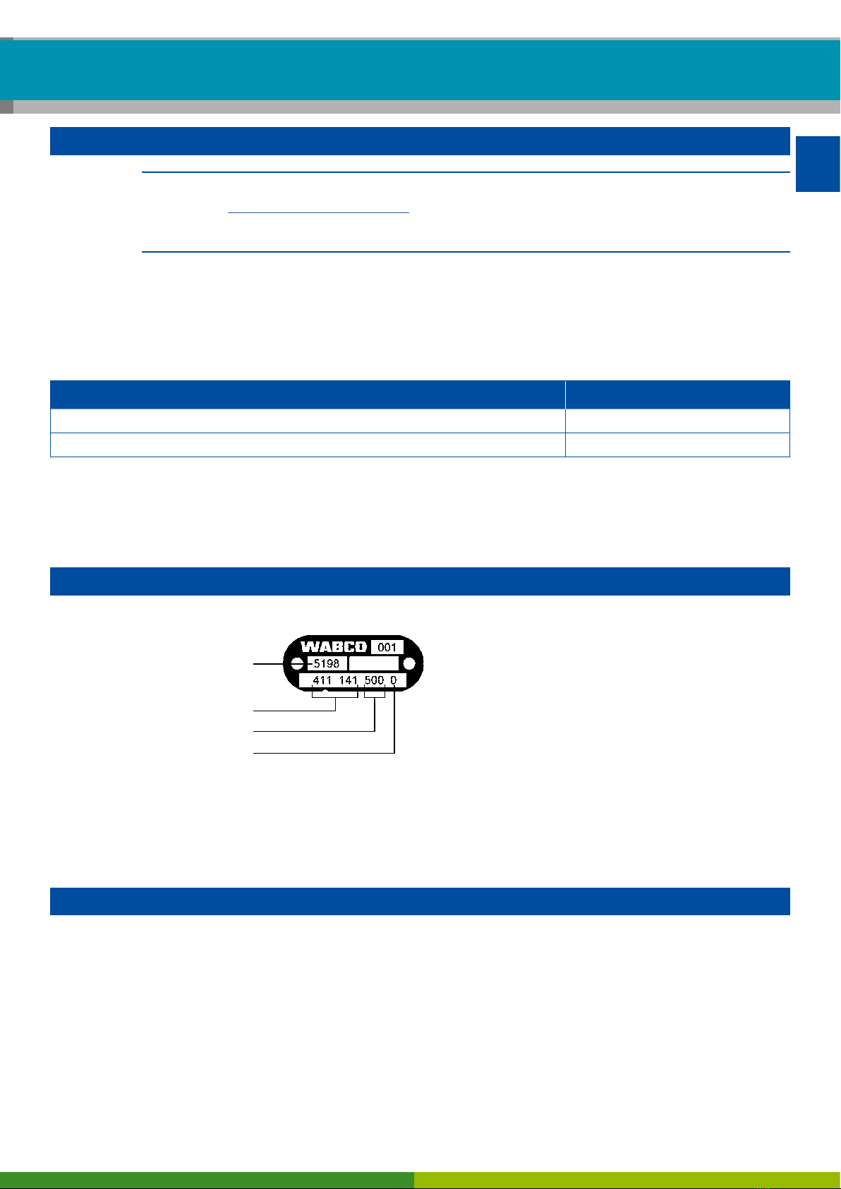
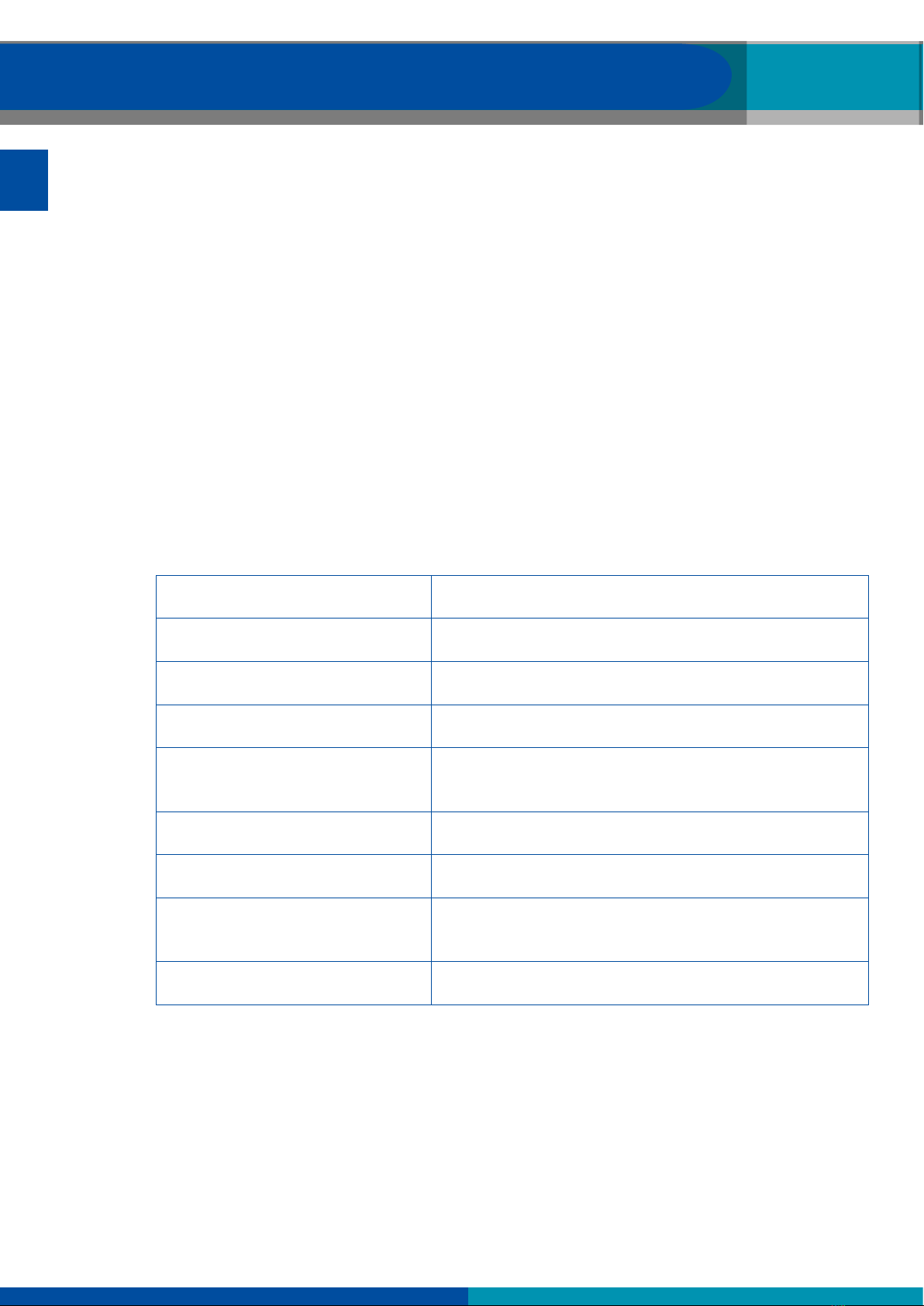
Structure of the WABCO product number
WABCO product numbers consist of 10 digits.
Production date
Type of device
Variant
Status digit
0 = New device (complete device)
1 = New device (subassembly)
2 = Repair kit or subassembly
4 = Component part
7 = Replacement device
R = Reman
Choose genuine WABCO parts
Genuine WABCO parts are made of high quality materials and are rigorously tested before they leave
our factories. You also have the assurance that the quality of every WABCO product is supported by an
outstanding WABCO customer service network.
As a leading supplier to the industry, WABCO collaborates with the world’s leading original equipment
manufacturers, and has the experience and capacities required to also satisfy the most stringent
production standards. The quality of every genuine WABCO part is supported by:

6
General information Safety information
EN
Tooling made for serial production
Regular sub-supplier audits
Exhaustive end-of-line tests
Quality standards < 50 PPM
Installing replica parts can cost lives – genuine WABCO parts protect your business.
WABCO additional services
The package you will get with a genuine WABCO part:
24-month product warranty
Overnight delivery
Technical support from WABCO
Professional training courses from the WABCO Academy
Access to diagnostics tools and support from the WABCO Service Partner network
Straightforward claims handling
Plus, of course, the condence that the Original Equipment Manufacturers’ rigorous quality standards
are met
WABCO Service Partner
WABCO Service Partners – the network you can rely on. You can access 2000 high quality workshops
with more than 6000 specialist mechanics, all trained to WABCO’s exacting standards and equipped
with our most up-to-the-minute systems diagnostic and support technology.
Your direct contact to WABCO
In addition to our online services, trained members of staff are there to help you at our WABCO Service
Partners to directly answer any technical or business-related questions you may have.
Contact us if you need assistance:
Find the right product
Diagnosis support
Training
You can nd your WABCO partner here:
http://www.wabco-auto.com/en/how-to-nd-us/contact/

7
Safety information
EN
2 Safety information
Observe all required provisions and instructions:
!WARNING: This product emits electromagnetic and electronically generated waves
that may interfere with the safe operation of pacemakers. Individuals that have
pacemakers should never use this product.
Read this publication carefully.
Adhere to all instructions, information and safety information to prevent injury to persons and damage to
property.
WABCO will only guarantee the safety, reliability and performance of their products and systems if all
the information in this publication is adhered to.
Always abide by the vehicle manufacturer's specications and instructions.
Observe all accident regulations of the respective company as well as regional and national regulations.
Make provisions for a safe work environment:
Only trained and qualied technicians may carry out work on the vehicle.
Do not use on live electrical circuits.
Risk of entanglement.
Wear safety goggles (user and bystanders).
Pedal actuations can lead to severe injuries if persons are in the vicinity of the vehicle. Make sure that
pedals cannot be actuated as follows:
Switch the transmission to "neutral" and actuate the hand brake.
Secure the vehicle against rolling by using chocks.
Fasten a visible note to the steering wheel indicating that work is being performed on the vehicle and
that the pedals are not to be actuated.
To reduce the risk of re, do not operate the tool in the vicinity of open containers or ammable liquids.
Do not use if the potential for explosive gas or vapors exists.
Keep the tool away from heat generating sources.
Do not operate the tool with the battery cover removed.
This device complies with Part 15 of the FCC Rules
Operation is subject to the following two conditions:
• This device will not cause harmful interference, and
• This device will accept any interference received, including interference that may cause undesired or
improper operation.
!Read the Warranty, Safety and Recycling information at the end of this user guide.

8
Safety information Components
EN
CAUTION!
Your Tire Pressure Monitoring (TPM) tool has been designed to be durable, safe, and reliable when
properly used.
All TPMS TOOLS are intended to be used only by qualied and trained automotive technicians or in a
light industrial repair shop environment. Please read all instructions below before using. Always follow
these safety instructions. If you have any questions pertaining to the safe or reliability use of this tool,
please call your local dealer.
Cleaning
Clean with a soft dry cloth, or if necessary, a soft damp cloth. Do not use any harsh chemical solvents
such as acetone, thinner, brake cleaner, alcohol, etc. as this may damage the plastic surface.
Water & Moisture
Do not use this tool where contact or immersion in water is a possibility. Never spill liquid of any kind
onto the tool.
Storage
Do not use or store the tool in an area where it is exposed to direct sunlight or excessive moisture.

9
Components
EN
3 Components
TPMS Manager
USB adapter
Plug type A
Plug type C
Plug type G
Plug type I
USB cable
Disc with TPMS software

10
Specications Functions
EN 4 Specications
Battery type: Rechargeable lithium ion
Battery life: Approximately 400 activations per full charge.
Dimensions (max. L,W,D): 6.5" x 3.7" x 1.5" (16.5 cm x 9.5 cm x 3.8 cm).
Case material: High impact ABS.
Response frequency: Main frequencies: 315 MHz and 433.92 MHz (support
for most of the specic frequencies).
Low battery indication: LCD bar graph display.
Weight: Approx. 2 lbs.
Temperature: Operating: -4° F to 131° F (-20° C to +55° C).
Storage: -40°F to 140° F (-40° C to +60° C).
Operating altitude: Up to 6560 ft (2000 m).

11
Functions
EN
5 Functions
Power ON /OFF switch Test or trigger sensor
Next, continue or conrm Cancel, previous step
Navigate to select "up" Navigate to select "down"
Navigate to select "left" Navigate to select "right"
1
2
3 4
5
1Antenna
2Result lights
3Trigger light
4Battery charge indicator and low bat light
5Keyboard

12
Operating instructions Operating instructions
EN 6 Operating instructions
6.1 Power ON/OFF
– Press the Power ON/OFF switch once to turn on the TPMS Manager
Ö1. Display of the currently used software version
ateq vt36
he1–03– 01
Ö2. Display of the MAIN MENU
about
MAIN MENU
– Press and hold the Power ON/OFF switch for up to 3 seconds to show the battery level
ÖDisplay of the battery level
battery level
– Press and hold the Power ON/OFF switch longer than 3 seconds to shut down the TPMS Manager.

13
Operating instructions
EN
6.2 Read/trigger sensor test
Before servicing the tires/wheels using your TPMS Manager, trigger each of the vehicle's sensors to
make sure they are working properly. This ensures that you are not liable for previously damaged or
defective sensors.
This procedure will not change the vehicle settings since the vehicle has not yet been put into learn/
retraining mode. This procedure allows you to quickly identify damaged or defective sensors, because
some vehicles do not indicate a damaged or defective sensor condition on the instrument cluster for up
to 20 minutes.
– Use left or right in the MAIN MENU to select TRIGGER SENSOR
MAIN MENU
trigger sensor
– Press OK
ÖThe SELECT SENSOR submenu is displayed
SELECT SENSOR
wabco wis
wabco wm2.2 read
wabco wm2.2 trig
wabco wm2.4 read
Available sensors
SENSOR NAME SENSOR TYPE
WIS Internally mounted sensor
WM 2.2 Externally mounted sensor produced up to calendar week 20 in 2017
WM 2.4 Externally mounted sensor produced after calendar week 20 in 2017
– Use up and down to select the sensor
– Press OK to conrm
ÖThe TPMS Manager is ready to trigger the sensor
WABCO WIS
return to menu
read sensor

14
Operating instructions Operating instructions
EN
– Hold the TPMS Manager at a distance of 5 cm to the sensor you want to check
– Press the TRIGGER SENSOR button and wait for a beep
ÖThe sensor data is displayed (example: WABCO WIS)
START MENU
WABCO WIS
4217397556 0,0 bar
22° c 433 mhzbat:ok
remaining 120 months
DECLARATION (EXAMPLE) MEANING
421 739 755 6 ID (identication number of the sensor)
22°C Air temperature during the test
REMAINING 120 MONTHS Lifetime remaining for new sensor
0.0 bar Pressure difference between tire inside and outside
433 MHz Radio frequency
BAT: OK Battery status
START Check again
MENU Back to the main menu
!The battery status and temperature of internally mounted sensors will only be displayed when the
sensor is read. In trigger mode, only ID and pressure are displayed.

15
Operating instructions
EN
6.3 Triggering procedure
The sensors can be tested in any order.
The OptiTireTM diagnostic software offers the option to trigger all sensors in a sequential order. When
choosing this option, the test is run anticlockwise beginning with the front, left-hand wheel. With twin
wheels, the left wheel (in driving direction) is tested rst.
Triggering the sensors in sequential order:
1
2 3
4 5 6 7
89
10

16
Operating instructions Operating instructions
EN
6.4 Settings
– Use left or right in the MAIN MENU to select SETTINGS
MAIN MENU
settings
– Press OK
ÖThe SETTINGS submenu is displayed
SETTINGS
lf power
units : bar/°c
buzzer on : yes
contrast: 85 %
– Use up or down in the SETTINGS menu to navigate
6.4.1 LF power
LF POWER means low frequency. The sensitivity of the sensors corresponds to the thickness of the
tire. For this reason, the power is adjustable. You can switch between the DEFAULT and 0-100% setting
for each sensor.
– Use up or down to select LF POWER
– Press OK to open the LF POWER submenu
– Use up or down to select a sensor
– Press OK
– Press up, left or right to increase the power
– Press down to decrease the power or switch to DEFAULT
– Press OK to conrm
– Press Cto return to the SETTINGS menu

17
Operating instructions
EN
6.4.2 Units
The TPMS Manager can measure temperature and air pressure in Celsius or Fahrenheit. The units can
be changed in the SETTINGS menu.
– Use up or down to select UNITS
– Press OK to enter the UNIT SELECTION submenu
– Use up or down to select a unit
– Press OK to conrm
– Press Cto return to the settings menu
Supported units:
BAR KILOPASCAL POUNDS PER SQUARE INCH
Celsius Bar / °C kPa / °C PSI / °C
Fahrenheit Bar / °F kPa / °F PSI / °F
6.4.3 Buzzer ON
The TPMS Manager can make a buzzer sound when a sensor is checked. The buzzer can be turned on
or off in the SETTINGS menu.
– Use up or down to select BUZZER ON
– Press OK
– Use up, down, left or right to toggle on or off
– Press OK to conrm
– Press Cto return to the SETTINGS menu
6.4.4 Contrast
The LCD contrast level can be adjusted from 0% to 100% in the SETTINGS menu.
– Use up or down to select CONTRAST
– Press OK
– Use up, left or right to increase the contrast
– Press down to decrease contrast
– Press OK to conrm
– Press Cto return to the SETTINGS menu
6.4.5 Auto off
The TPMS Manager can be turned off automatically after a dened period of non-use. The time can be
adjusted from 1 minute to 60 minutes or the function can be disabled.
– Use down to select AUTO OFF
– Press OK
– Use up, left or right to increase the period of time
– Press down to decrease the period of time or switch to DISABLED
– Press OK to conrm
– Press Cto return to the SETTINGS menu

18
Operating instructions Operating instructions
EN
6.5 About
The ABOUT menu displays the current version of the software and information about the device.
– Use left or right in the MAIN MENU to select ABOUT
about
MAIN MENU
– Press OK
ÖThe ABOUT screen is displayed
ABOUT
sn:
version:
receiver 1:
receiver 2:
k360–15088
he–03–01
ready
––––
6.6 Language
The LANGUAGE menu can be used to change the language of all the menus in TPMS Manager.
– Use left or right in the MAIN MENU to select LANGUAGE
MAIN MENU
language
– Press OK
ÖThe LANGUAGE menu is displayed
LANGUAGE
cestina
dansk
deutsch
english
Complete listing (alphabetical order):
Cestina, Chinese, Dansk, German, Dutch, English, French, Hebrew, Italian, Maqyar, Norsk, Polish,
Portuguese, Roman, Russian, Slovencina, Slovenscina, Spanish, Suomi, Svedish, Turkish

19
Operating instructions
EN
6.7 Recent sensor data
The RECENT SENSOR DATA menu can be used to display or erase the last sensor data that was read
out.
– Use left or right in the MAIN MENU to select RECENT SENSOR DATA
MAIN MENU
recent sensor data
– Press OK
ÖThe RECENT SENSOR DATA menu is displayed
RECENT SENSOR DATA
view data
erase records
– Use up or down to select VIEW DATA* or ERASE RECORDS
– Press OK to conrm
– Press Cto return to the SETTINGS menu
Ö*If the memory is empty, the device will show the message "NO DATA"
no data

20
Charging Tool update
EN 7 Charging
Low battery indication
The TPMS Manager runs on 5 Volt and has an integrated low battery detection circuit. A fully charged
battery can carry out around 400 sensor tests (approximately 80-100 cars). A full charge takes about 6
hours.
When the battery is low, the battery screen will ash with the message "LOW".
When the battery is low, the "status bar" appears every 10 seconds. This display will stop when the
battery has no more power.
7.1 Battery charging
1
– Plug the USB cable into the USB port (1) of the TPMS Manager
– Plug the USB cable into the charger adapter (2)
– Plug the charger adapter into an appropriate output
ÖThe red LED CHARGE light will light up
ÖOnce charged, the LED CHARGE light will turn green
!Use of the TPMS Manager with a low battery status is not recommended because the transmission may
not be reliable.
7.2 Battery replacement
The TPMS Manager must be returned to the factory for battery replacement.
!Do not open the TPMS Manager or to tamper with the seal attached to the TPMS Manager. Once the
seal is broken the warranty is void.
Other manuals for TPMS MANAGER
1
Table of contents
Other WABCO Diagnostic Equipment manuals