WAC InvisiLED T24-TW3 User manual

INSTALLATION INSTRUCTION
InvisiLED Tunable White
T24-TW3
Waclighting.com
Phone (800) 526.2588
Fax (800) 526.2585
Headquarters/Eastern Distribution Center
44 Harbor Park Drive
Port Washington, NY 11050
Central Distribution Center
1600 Distribution Ct
Lithia Springs, GA 30122
Western Distribution Center
1750 Archibald Ave
Ontario, CA 91761
WAC Lighting retains the right to modify the design of our products at any time as part of the company's continuous improvement program. OCT. 20221.
SAFETY INSTRUCTION
IMPORTANT: NEVER attempt any work without shutting off the electricity.
•Always turn off power at fuse box prior to installation to prevent electrical shock.
•Intended for indoor use. Dry and damp locations.
•Install in accordance with national electric code, and local regulations.
•Consult with local inspector to assure compliance.
•Do not submerge or install within 5 feet of a swimming pool.
•Do not connect the tape directly to high voltage power
CAUTION – TO REDUCE RISK OF FIRE AND ELECTRICAL SHOCK
•Read all instructions before installing.
•Handle product with care.
•Do not conceal or extend exposed conductors through a building wall
•To reduce the risk of fire and burns, do not install this lighting system where the exposed bare conductors can be shorted or contact any
conductive materials
•To reduce the risk of overheating and potential fire risk, make sure all connections are tight.
•Do not install any fixture assembly closer than 6 in. from any curtain, or similar combustible material.
•Do not modify or disassemble product beyond instructions or warranty will be void.
•Failure to follow safety warnings, and installation instruction will void the warranty
ATTENTION - AFIN DE RÉDUIRE LES RISQUES D'INCENDIE ET DE CHOC ÉLECTRIQUE
• Lire toutes les instructions avant d'installer.
• Manipuler le produit avec soin.
• Ne pas dissimuler et faire passer les conducteurs exposés à travers un mur de bâtiment.
• Afin de réduire les risques d'incendie et de brûlures, ne pas installer ce système d'éclairage là où les conducteurs dénudés peuvent être court-
circuités, ou entrer en contact avec des matériaux conducteurs.
• Afin de réduire le risque de surchauffe et d'incendie potentiel, s'assurer que toutes les connexions sont bien serrées.
• Ne pas installer aucun luminaire à moins de 6 pouces d'un rideau ou d'un matériau combustible similaire.
• Ne pas modifier ou démonter le produit au-delà des instructions sous peine d'annuler la guarantie.
• Ne pas respecter les avertissements de sécurité et des instructions d'installation annulera la garantie.
WIRING AND INSTALLATION:
1. Turn Power off at circuit breaker (See FIG. 1)
FIG. 1
2. Mounting 24VDC Class 2 remote power supply and WAC Wireless DMX LED
Controller at desired location. (See FIG. 2)
FIG. 2
Do not bend the tape light to
a diameter less than 4 inches
Do not bend the tape light
on a horizontal plane
Do not fold or
twist LED Tape
Do not cover LED tape
light with any materials
Do not power the LED
tape while attached to the
spool or tightly coiled
Avoid contact with sharp
objects
Install on stable
clean, dry surface

INSTALLATION INSTRUCTION
InvisiLED Tunable White
T24-TW3
Waclighting.com
Phone (800) 526.2588
Fax (800) 526.2585
Headquarters/Eastern Distribution Center
44 Harbor Park Drive
Port Washington, NY 11050
Central Distribution Center
1600 Distribution Ct
Lithia Springs, GA 30122
Western Distribution Center
1750 Archibald Ave
Ontario, CA 91761
WAC Lighting retains the right to modify the design of our products at any time as part of the company's continuous improvement program. Oct. 20222.
3. Measured a distance between power supply and DMX controller to the beginning of the tape run. Choose between two options below to wire
the power and data communication to the tape. When choosing wire, factor in voltage drop, amperage rating, shield/unshielded, and type (in-wall
rated).
Option A: Unshielded Cable 25 ft. maximum distance between power supply to the beginning of the tape
The WAC In wall rated 20 AWG unshielded cable can be used to wire between a power supply-Wireless DMX LED Controller to the beginning of
the tape up to 25 ft. Smaller gauge wire number (bigger conductor) can be used, but the maximum run length limitation remains at 25 ft. due data
communication distortion if it’s run over 25 ft. (See FIG. 3) Wire color connection is shown in Table 1.
Table. 1
Wire Color Connection
Wireless DMX LED Controller Terminal
Color
T24-EX3-* Cable Tape marking
RED RED +24VDC (RED)
WHITE WHITE DATA (WHITE)
BLACK BLACK - (BLACK)
FIG. 3
Option B: Shielded data Cable 90 ft. maximum distance between power supply to the beginning of the tape
A shield data cable shall be used to connect between the power supply-Wireless DMX LED Controller to the beginning of the tape up to 90 ft. (See
FIG. 4)
ICE cable model number: Control Yellow is recommended. Product information can be found below:
https://www.icecable.com/products/control-yellow
https://icecable.s3.amazonaws.com/uber_products/specs/000/000/078/original/Control_Yellow.pdf?1435595602
For Plenum spaces, ICE cable Control Yellow Plenum is recommended. https://www.icecable.com/products/control-yellow-plenum
Both drain and common conductor wires shall be connected to a black terminal of Wireless DMX LED Controller. Another end shall be connected to
the black wire of connector cable. The signal conductor shall be connected to the white terminal of Wireless DMX LED Controller. Another end shall
be connected to the white wire of connector cable. The power cable can be either shielded or unshielded cable. The bigger conductor yields less
voltage drop. The +24VDC polarity shall be connected to the red terminal on Wireless DMX LED Controller. Another end shall be connected to the
red wire of connector cable. The -24VDC or common conductor wire shall be connected to a black terminal of Wireless DMX LED Controller.
Another end shall be connected to the black wire of connector cable. (see FIG. 5)
T24-B-WT (5-3 terminal box) may be used to connect between 5 wires of shield cable to 3 wires of InvisiLED tape connector.
FIG. 4
Shielded Data Cable
90 FT MAX

INSTALLATION INSTRUCTION
InvisiLED Tunable White
T24-TW3
Waclighting.com
Phone (800) 526.2588
Fax (800) 526.2585
Headquarters/Eastern Distribution Center
44 Harbor Park Drive
Port Washington, NY 11050
Central Distribution Center
1600 Distribution Ct
Lithia Springs, GA 30122
Western Distribution Center
1750 Archibald Ave
Ontario, CA 91761
WAC Lighting retains the right to modify the design of our products at any time as part of the company's continuous improvement program. Oct. 20223.
FIG. 5
DMX CONTROLLER-OUTPUT
BlackWhiteRed
Black
White
Red
Red
White
Black
Drain
Blue
Drain
Drain
Blue
Black
White
Red
BlueRed White Black
4. To extend an unshielded cable length (if needed), In Wall Rated Joiner Cable (T24-IC-*) and Joiner Cable Extender (T24-FF-WT) can be
used to join between sections as shown in FIG. 6
FIG. 6
5. To extend the cable length between Wireless DMX LED Controller cable or a wiring box to a tape sections, (if needed), In Wall Rated
Extension cable (T24-EX3-*) can be used to join between sections by soldering as shown in FIG. 7. Wire color connection is shown in the
Table 1.
FIG. 7
6. Measure the desired length of tape light and round it off to the nearest 4-inch interval. Determine necessary quantities of other
accessories and power supply need for each run. (See FIG. 8)
FIG. 8
T24-IC-*
T24-FF-WT
T24-EX3-*
Shielded Data Cable
Manufacturer: ICE Cable
Model: Control Yellow
RED/BLACK: POWER
WHITE/BLUE: DATA
DRAIN: SHIELD FOR EFFECTIVE GROUNDING

INSTALLATION INSTRUCTION
InvisiLED Tunable White
T24-TW3
Waclighting.com
Phone (800) 526.2588
Fax (800) 526.2585
Headquarters/Eastern Distribution Center
44 Harbor Park Drive
Port Washington, NY 11050
Central Distribution Center
1600 Distribution Ct
Lithia Springs, GA 30122
Western Distribution Center
1750 Archibald Ave
Ontario, CA 91761
WAC Lighting retains the right to modify the design of our products at any time as part of the company's continuous improvement program. Oct. 20224.
7. Determine the maximum run according to specific CCT range as shown in reference Table 2.
A lower light output can be adjusted by lowering DMX value in the same ratio to keep the same CCT.
Note: Setting the maximum DMX value at lower number will increase the maximum run length as the tape consume less power.
Table 2.
DMX Value
CCT (K) Current (A/ft) Power (W/ft) Max Run (ft) Lumen CH1: 1800K CH2: 2700K CH3: 5000K
1800 0.1429 3.38 28 170 255 0
1900 0.1739 4.15 23 220 255 59
2000 0.2000 4.77 20 260 255 120
2100 0.2500 5.70 16 314 255 210
2200 0.2222 5.31 18 295 170 255
2300 0.2105 4.83 19 270 123 255
2400 0.1818 4.33 22 240 75 255
2500 0.1667 3.86 24 212 35 255
2600 0.1538 3.58 26 196 13 255
2700 0.1429 3.37 28 183 255 0
2800 0.1538 3.57 26 198 255 12
2900 0.1600 3.74 25 210 255 25
3000 0.1667 3.91 24 222 255 38
3100 0.1739 4.15 23 238 255 60
3200 0.1905 4.45 21 259 255 87
3300 0.2000 4.76 20 280 255 115
3400 0.2105 5.01 19 296 255 140
3500 0.2353 5.39 17 327 255 180
3600 0.2500 5.80 16 351 255 220
3700 0.2667 6.03 15 367 240 255
3800 0.2500 5.70 16 347 210 255
3900 0.2353 5.41 17 330 180 255
4000 0.2222 5.12 18 311 150 255
4100 0.2105 4.85 19 293 123 255
4200 0.2000 4.60 20 278 100 255
4300 0.1905 4.45 21 269 85 255
4400 0.1818 4.30 22 260 72 255
4500 0.1739 4.13 23 248 56 255
4600 0.1739 4.01 23 241 46 255
4700 0.1667 3.87 24 232 35 255
4800 0.1600 3.75 25 224 25 255
4900 0.1538 3.66 26 217 16 255
5000 0.1538 3.57 26 213 11 255
Any CCT or CCT mixing in between will maintain the light output as long as the tape voltage is higher than 20.4VDC. The light output (Lumens)
starts to degrade as a tape voltage gets lower as shown in FIG. 10
The tape voltage can be checked using voltage meter probe to measure the DC voltage between soldering point of RED and BLACK on the tape as
shown in FIG. 9

INSTALLATION INSTRUCTION
InvisiLED Tunable White
T24-TW3
Waclighting.com
Phone (800) 526.2588
Fax (800) 526.2585
Headquarters/Eastern Distribution Center
44 Harbor Park Drive
Port Washington, NY 11050
Central Distribution Center
1600 Distribution Ct
Lithia Springs, GA 30122
Western Distribution Center
1750 Archibald Ave
Ontario, CA 91761
WAC Lighting retains the right to modify the design of our products at any time as part of the company's continuous improvement program. Oct. 20225.
In order to maintain a voltage or having less voltage drop on the tape, bigger conductor wire or lower gauge wire number is recommended.
FIG. 9
FIG. 10
0
10
20
30
40
50
60
70
80
90
100
110
15 16 17 18 19 20 21 22 23 24
Relative Percentage of Light Output
Tape Voltage (VDC)
Linear Tunable White

INSTALLATION INSTRUCTION
InvisiLED Tunable White
T24-TW3
Waclighting.com
Phone (800) 526.2588
Fax (800) 526.2585
Headquarters/Eastern Distribution Center
44 Harbor Park Drive
Port Washington, NY 11050
Central Distribution Center
1600 Distribution Ct
Lithia Springs, GA 30122
Western Distribution Center
1750 Archibald Ave
Ontario, CA 91761
WAC Lighting retains the right to modify the design of our products at any time as part of the company's continuous improvement program. Oct. 20226.
If need, a tape votlage drop along the run length can be calculated using the Table 3 below. The voltage drop value in the table shown is at
maximum brightness condition. Lowering the light output will lower the voltage drop along the tape.
Table 3.
Voltage Drop at different Tape Distance (VDC) @Full light output
Tape Distance →
1
2
3
4
5
6
7
8
9
10
11
12
13
14
15
16
17
18
19
20
21
1800K
0.07
0.07
0.13
0.20
0.26
0.33
0.40
0.46
0.53
0.59
0.66
0.73
0.79
0.86
0.92
0.99
1.06
1.12
1.19
1.25
1.32
1900K
0.09
0.09
0.18
0.27
0.36
0.45
0.54
0.63
0.72
0.81
0.90
0.99
1.08
1.17
1.27
1.36
1.45
1.54
1.63
1.72
1.81
2000K
0.09
0.09
0.18
0.28
0.37
0.46
0.55
0.64
0.74
0.83
0.92
1.01
1.10
1.20
1.29
1.38
1.47
1.56
1.66
1.75
1.84
2100K
0.09
0.09
0.18
0.28
0.37
0.46
0.55
0.65
0.74
0.83
0.92
1.02
1.11
1.20
1.29
1.39
1.48
1.57
1.66
1.75
1.85
2200K
0.09
0.09
0.18
0.27
0.37
0.46
0.55
0.64
0.73
0.82
0.92
1.01
1.10
1.19
1.28
1.37
1.46
1.56
1.65
1.74
1.83
2300K
0.09
0.09
0.18
0.27
0.36
0.45
0.54
0.63
0.72
0.81
0.90
0.99
1.08
1.17
1.26
1.35
1.44
1.54
1.63
1.72
1.81
2400K
0.09
0.09
0.18
0.27
0.35
0.44
0.53
0.62
0.71
0.80
0.88
0.97
1.06
1.15
1.24
1.33
1.42
1.50
1.59
1.68
1.77
2500K
0.08
0.08
0.15
0.23
0.31
0.39
0.46
0.54
0.62
0.70
0.77
0.85
0.93
1.00
1.08
1.16
1.24
1.31
1.39
1.47
1.54
2600K
0.07
0.07
0.14
0.21
0.29
0.36
0.43
0.50
0.57
0.64
0.71
0.79
0.86
0.93
1.00
1.07
1.14
1.21
1.29
1.36
1.43
2700K
0.07
0.07
0.13
0.20
0.26
0.33
0.39
0.46
0.53
0.59
0.66
0.72
0.79
0.85
0.92
0.99
1.05
1.12
1.18
1.25
1.32
2800K
0.08
0.08
0.16
0.23
0.31
0.39
0.47
0.55
0.62
0.70
0.78
0.86
0.94
1.01
1.09
1.17
1.25
1.33
1.40
1.48
1.56
2900K
0.08
0.08
0.17
0.25
0.33
0.41
0.50
0.58
0.66
0.75
0.83
0.91
0.99
1.08
1.16
1.24
1.33
1.41
1.49
1.57
1.66
3000K
0.09
0.09
0.18
0.27
0.36
0.45
0.54
0.63
0.72
0.81
0.90
0.99
1.08
1.17
1.26
1.35
1.44
1.53
1.62
1.71
1.80
3100K
0.09
0.09
0.18
0.27
0.36
0.45
0.54
0.64
0.73
0.82
0.91
1.00
1.09
1.18
1.27
1.36
1.45
1.54
1.63
1.72
1.81
3200K
0.09
0.09
0.18
0.27
0.36
0.46
0.55
0.64
0.73
0.82
0.91
1.00
1.09
1.18
1.28
1.37
1.46
1.55
1.64
1.73
1.82
3300K
0.09
0.09
0.18
0.28
0.37
0.46
0.55
0.64
0.73
0.83
0.92
1.01
1.10
1.19
1.28
1.38
1.47
1.56
1.65
1.74
1.83
3400K
0.09
0.09
0.18
0.28
0.37
0.46
0.55
0.65
0.74
0.83
0.92
1.02
1.11
1.20
1.29
1.39
1.48
1.57
1.66
1.76
1.85
3500K
0.09
0.09
0.18
0.28
0.37
0.46
0.55
0.65
0.74
0.83
0.92
1.02
1.11
1.20
1.29
1.38
1.48
1.57
1.66
1.75
1.85
3600K
0.09
0.09
0.18
0.27
0.37
0.46
0.55
0.64
0.73
0.82
0.92
1.01
1.10
1.19
1.28
1.37
1.47
1.56
1.65
1.74
1.83
3700K
0.09
0.09
0.18
0.28
0.37
0.46
0.55
0.65
0.74
0.83
0.92
1.02
1.11
1.20
1.29
1.38
1.48
1.57
1.66
1.75
1.85
3800K
0.09
0.09
0.18
0.28
0.37
0.46
0.55
0.65
0.74
0.83
0.92
1.02
1.11
1.20
1.29
1.38
1.48
1.57
1.66
1.75
1.85
3900K
0.09
0.09
0.18
0.27
0.37
0.46
0.55
0.64
0.73
0.82
0.92
1.01
1.10
1.19
1.28
1.37
1.47
1.56
1.65
1.74
1.83
4000K
0.09
0.09
0.18
0.27
0.37
0.46
0.55
0.64
0.73
0.82
0.91
1.00
1.10
1.19
1.28
1.37
1.46
1.55
1.64
1.73
1.83
4100K
0.09
0.09
0.18
0.27
0.36
0.45
0.55
0.64
0.73
0.82
0.91
1.00
1.09
1.18
1.27
1.36
1.45
1.55
1.64
1.73
1.82
4200K
0.09
0.09
0.18
0.27
0.36
0.45
0.54
0.63
0.72
0.81
0.90
0.99
1.08
1.17
1.26
1.35
1.44
1.53
1.62
1.71
1.80
4300K
0.09
0.09
0.18
0.27
0.36
0.45
0.54
0.63
0.72
0.81
0.90
0.99
1.08
1.16
1.25
1.34
1.43
1.52
1.61
1.70
1.79
4400K
0.09
0.09
0.17
0.26
0.35
0.44
0.52
0.61
0.70
0.79
0.87
0.96
1.05
1.13
1.22
1.31
1.40
1.48
1.57
1.66
1.74
4500K
0.08
0.08
0.17
0.25
0.34
0.42
0.51
0.59
0.67
0.76
0.84
0.93
1.01
1.10
1.18
1.26
1.35
1.43
1.52
1.60
1.69
Example:
Project: 1800K – 5000K InvisiLED Tunable White Light
Distance between DMX Controller to beginning of the tape: 50 ft using 20 AWG
InvisiLED Tunable White Tape Max Run: 15 ft.
1ft. Tape Current (Worst case at 3700K): 0.2667 A
15 ft. Tape Current: 0.2751 X 15 = 4 A
Resistane of 20AWG (WAC’s Unshielded cable) per ft: 0.0206 Ω
Voltage drop from wires between DMX Controller to tape: 4 X (50 X 0.0206) = 4.12V
Voltage at beginning of the InvisiLED Tunable White tape: 24 – 4.12 = 19.88V
Light Output at beginning of the tape: According to FIG. 10, it’s at around 90% with 19.8V. So you would expect 90% of light
output that shown in Table 2.
Voltage at the end of InvisiLED Tunable White tape: According to Table 3, the 15ft tape voltage drop is 1.29V at 3700K,
thus 19.8 – 1.29 = 18.51 VDC
Light Output at the end of InvisiLED Tunable White tape: According to FIG. 10, it’s around 57% at 18.51V. So you would expect 57% of light
output that shown in Table 2.

INSTALLATION INSTRUCTION
InvisiLED Tunable White
T24-TW3
Waclighting.com
Phone (800) 526.2588
Fax (800) 526.2585
Headquarters/Eastern Distribution Center
44 Harbor Park Drive
Port Washington, NY 11050
Central Distribution Center
1600 Distribution Ct
Lithia Springs, GA 30122
Western Distribution Center
1750 Archibald Ave
Ontario, CA 91761
WAC Lighting retains the right to modify the design of our products at any time as part of the company's continuous improvement program. Oct. 20227.
8. If necessary, cut InvisiLED Tunable White tape light to desired length at line indicated with scissors icon. The tape allows for a cut every
4-inch interval. The cut line is shown on both sides of connector. (See FIG. 11)
FIG. 11
9. Mount InvisiLED Tunable White tape light: clean surface before mounting. Peel off 3M VHB adhesive backing covers off as strip is
installed, pressing firmly to mounting surface in increments. (See FIG. 12)
FIG. 12
10. Joining between InvisiLED Tunable White tape light
InvisiLED Tunable White tape light has a polarity which means the red color bar has to be same side (See FIG. 13). Joining a tape in an
opposite direction will lose an ability to control the tape even though the tape lit up.
Joining tape together (If necessary), the following accessories can be used to join between tapes section depending on your application:
Tape to Tape Connector (T24-MM-WT), See FIG. 13
FIG. 13
Peel back during
installation
Adhesive back cover
RED Color Bar
RED Color Bar

INSTALLATION INSTRUCTION
InvisiLED Tunable White
T24-TW3
Waclighting.com
Phone (800) 526.2588
Fax (800) 526.2585
Headquarters/Eastern Distribution Center
44 Harbor Park Drive
Port Washington, NY 11050
Central Distribution Center
1600 Distribution Ct
Lithia Springs, GA 30122
Western Distribution Center
1750 Archibald Ave
Ontario, CA 91761
WAC Lighting retains the right to modify the design of our products at any time as part of the company's continuous improvement program. Oct. 20228.
Tape to Tape T Connector (T24-TI-WT), See FIG. 14 Tape to Tape X Connector (T24-XI-WT) , See FIG. 15
FIG. 14 FIG. 15
1
Tape to Tape L Connector (T24-LI-WT) , See FIG. 16 Flex Tape to Tape Y Connector (T24-Y-WT) , See FIG. 17
FIG. 16 FIG. 17
Flex Tape to Tape X Connector (T24-X-WT) , See FIG. 18
FIG. 18
11. Connect electrical power feed connector to any connector on the tape or accessories. Make sure the connection direction is correct.
Feed power from the left
(RED Color Bar shall be on the top of the tape, See FIG. 19)
FIG. 19
Feed power from the right
(RED Color Bar shall be at the bottom of the tape, See FIG. 20)
FIG. 20
RED color bar (Bottom)
RED color bar (Top)
RED color bar (Bottom)
RED color bar (Top)

INSTALLATION INSTRUCTION
InvisiLED Tunable White
T24-TW3
Waclighting.com
Phone (800) 526.2588
Fax (800) 526.2585
Headquarters/Eastern Distribution Center
44 Harbor Park Drive
Port Washington, NY 11050
Central Distribution Center
1600 Distribution Ct
Lithia Springs, GA 30122
Western Distribution Center
1750 Archibald Ave
Ontario, CA 91761
WAC Lighting retains the right to modify the design of our products at any time as part of the company's continuous improvement program. Oct. 20229.
SYSTEM DIAGRAM:
InvisiLED Tunable White shall be used with WAC Wireless DMX LED Controller at all times. Using other Wireless DMX LED Controller brands will
result in losing an ability to control InvisiLED Tunable White tape light. The following diagram is provided as example system design. (See FIG. 21 &
22)
FIG. 21
FIG. 22

INSTALLATION INSTRUCTION
InvisiLED Tunable White
T24-TW3
Waclighting.com
Phone (800) 526.2588
Fax (800) 526.2585
Headquarters/Eastern Distribution Center
44 Harbor Park Drive
Port Washington, NY 11050
Central Distribution Center
1600 Distribution Ct
Lithia Springs, GA 30122
Western Distribution Center
1750 Archibald Ave
Ontario, CA 91761
WAC Lighting retains the right to modify the design of our products at any time as part of the company's continuous improvement program. Oct. 202210.
TROUBLESHOOTING
Symptom Common Cause and Solution
Light Output turns on/off repeatedly or flashing The tape consumes too much power than a capacity of power supply.
WAC power supply has an overload protection that will trip the internal
auto-reset. Exceeding power capacity will repeatedly reset the power
supply until an overload condition is removed.
Light output flashes wildly with different CCT The data signal communication between Wireless DMX LED Controller
and InvisiLED TUNABLE WHITE tape has a high distortion due to a
long run of wires between Power Supply-Wireless DMX LED Controller
and InvisiLED Tape. The shield data cable is recommended to use to
maintain a good quality data signal. Reducing the run length between
Wireless DMX LED Controller to the tape will help solving the problem.
No light from one section to the end of the run /
Light output flashes wildly with different CCT from one section to
the end of the run
The InvisiLED TUNABLE WHITE tape may be damaged due to high
degree of bending angle and cause a soldering on the tape to crack and
lose electrical solution. To solve this issue quickly is by cutting and
remove the first unlit 4 inches long section out and reconnecting the rest
of the tape.
Light output at the end of the run is dim
High contrast between beginning and the end of run.
This is the voltage drop effects. Using a thicker conductor wire or
smaller gauge wire number yields less voltage drop and boost light
output up.
Another way is to lower a maximum DMX value to reduce the current
consumption to InvisiLED TUNABLE WHITE tape. Thus, a contrast
between beginning and the end of InvisiLED tape run will be smaller.
Make sure that no ELV/TRIAC dimmer is connected to power supply.
InvisiLED TUNABLE WHITE is only control through Wireless DMX LED
Controller
InvisiLED Tunable White light overheats Incorrect voltage pairing, ensure 24V tape light are not paired with a
power supply with higher voltage
Incorrect ambient temperature. Ensure tape light is installed in
environment -4° - 104°F (-20°C - 40°C)
Lower the maximum light output down to acceptable ranges as
recommended in Table. 2
InvisiLED Tunable White does not illuminate Power Supply Failure, using voltage meter to check.
Incorrect wiring, polarity of positive and negative are reversed.
Incorrect DMX Channel setup, Check the DMX channel setup and
properly activate the right channel.
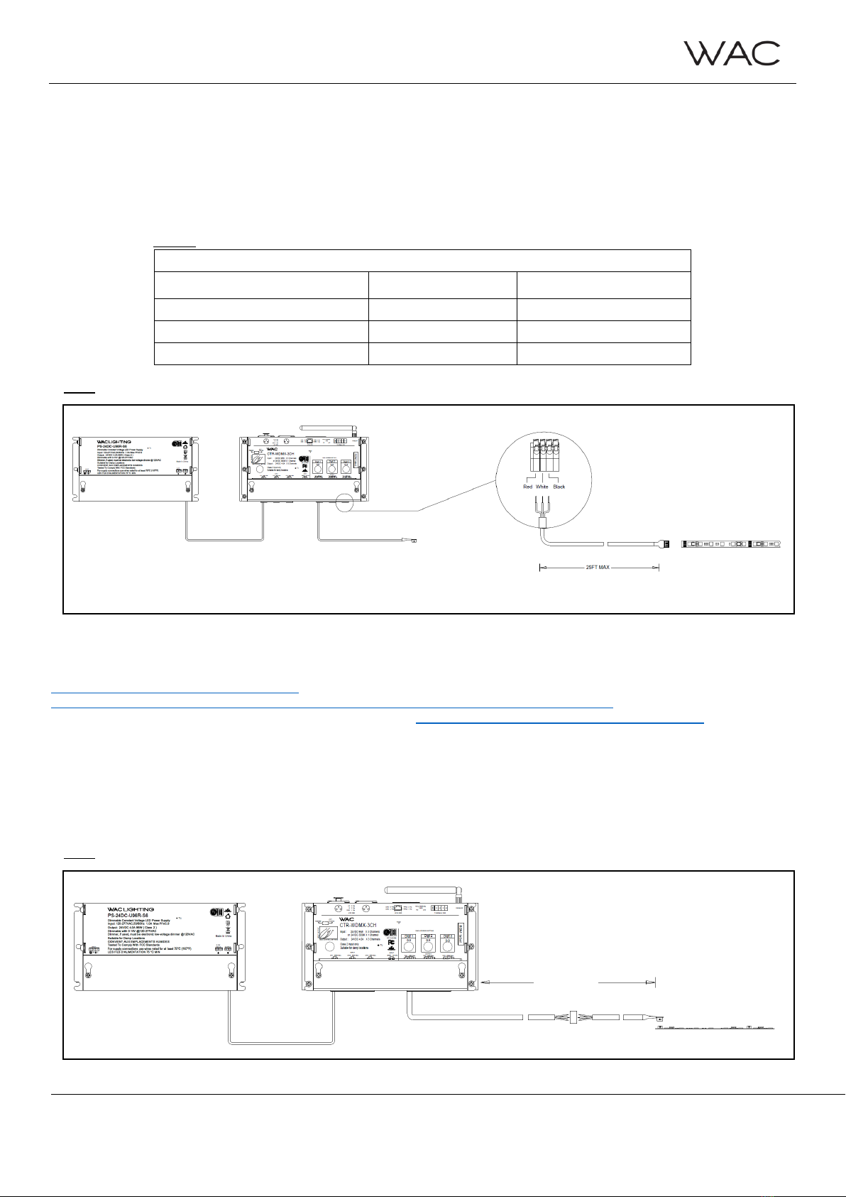
Unable to dim InvisiLED Tunable White light Make sure a right connection between power feed to tape (See FIG. 19-
20)
Make sure a RED color bar is on a right side for all connections between
tape to tape.
Sudden Loss control over InvisiLED Tunable White Light This scenario may happen when you lose control over InvisiLED
Tunable White suddenly as you ramp up the brightness or increase the
power to the tape. This cause by a combination of voltage drop and data
quality loss.
To regain control over tape light, please remove the power to the tape,
lower the DMX value, and use shield data cable. Make sure that both
common and drain wires are all connected on both ends. Or reduce the
run length between Wireless DMX LED Controller to the tape.
Unable to light up all 3 CCTs (1800K, 2700K, 5000K) at the same
time
This feature has been designed in the Wireless DMX LED Controller
CTR-WDMX-3CH to prevent an overflow of power to InvisiLED Tunable
White tape that will cause an overheat. Thus, only two CCTs can be on
at the same time by turning off one of CH1 to CH3 to zero. CH1 (1800K)
has highest priority. CH2 (2700K) has second priority and CH3 (5000K)
is at last.
Table of contents
Other WAC Lighting Equipment manuals