•
, ,.
,
,
•
•
•
,
..
--------
------
,
~--~
'
-------------------------------------------
"•
......
"
..
'.
.
';t
.
..'."'
•
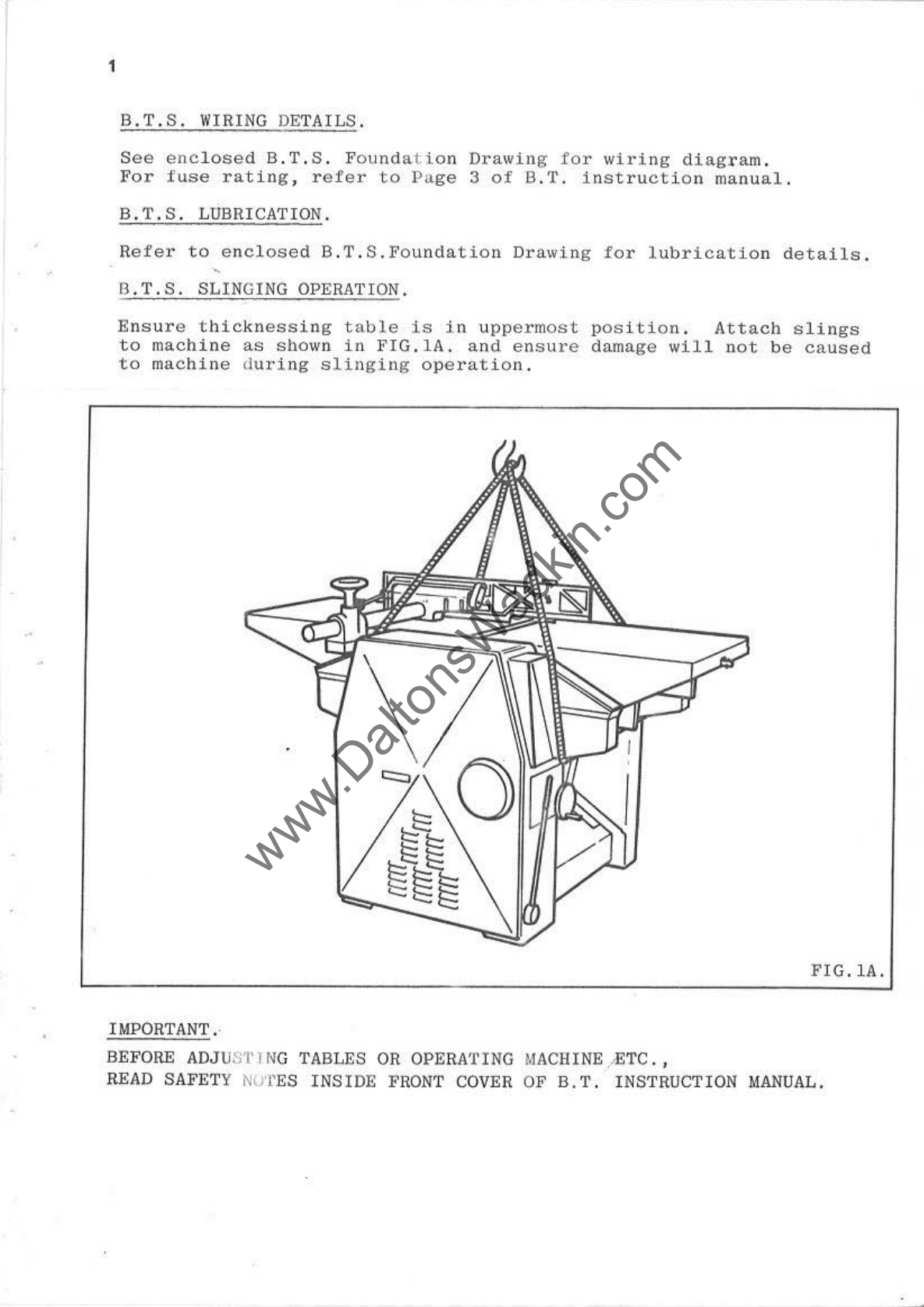
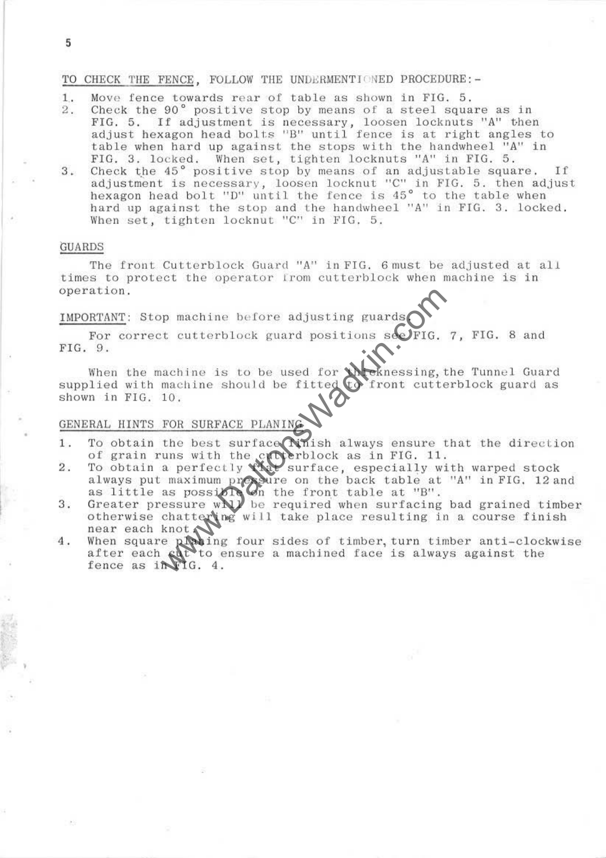
BTS SURFACING TABLE
INSTRUCTIONS
•
•
•
,
NOTE
:
THE
BA
SIC
CONSTRUCTION
OF
OUR
BTS
MACHINE
IS
THE
SAME
AS
THE
BT
THICKNESSER
WITH
THE
ADDITION
OF
TOP
SURFACING
TABLES
.
THE
BASIC
BT
INSTRUCTION
BOOK
IS
THEREFORE VALID APART
FROM
THE
TOP TABLES WHICH
ARE
S
HOWN
IN
THESE SUPPLEMENTARY INSTRUCTIONS.