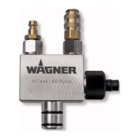
WAGNER PI-P1 User manual

08/2008 0241891
http://www.wagner-group.com
Operating Manual
Powder injectors
DANGER
High Voltage!
Turn power off
before servicing!
CAUTION
Read rules for safe
operation and
instructions
carefully!
PI-P1 and PI-F1
C
E
R
T
I
F
I
E
D
D
I
N
I
S
O
9
0
0
1

Introduction
20241891 – PI-P1 / PI-F1 08/2008
Powder injector PI - P1 Article No. 0241621
Powder injector PI - F1 Article No. 0241622
28mm
110mm
F
A
S
D
0241621_01b
APowder inlet from powder container
FFeed air inlet
DDosage air inlet
SPowder/air mixture outlet to gun
The switched air mode:
No powder is fed to Aif the feed air Fis
switched off and, simultaneously, the
dosage air quantity Dis increased to
maximum level.
No new powder Ais fed to the spray
gun, while the powder feed hose Sis
regularly purged with dosage air. The
powder flow Astarts immediately as
soon as the feed air is switched on
again and the dosage air is switched to
normal quantity.
The powder injector is used for powder feeding in manual as well as automatic powder coating
systems. In addition to this, the powder injector is also ideally suitable for switching mode.
All types of coating powder can be processed with the injector.
A choice of two powder injectors is available:
• powder injector PI-P1 and
• powder injector PI-F1
The PI-P1 powder injector is connected to control units, which regulate air pressure.
The PI-F1 powder injector, on the other hand, is connected to control units which control the
compressed air flow rate, making this powder injector suitable for applications involving control
units with AFC technology (flow rate control) and purging air mode for powder flow.
Both powder injectors can be operated with the following control units:
• powder injector PI-P1 with EPG 2008/EPG Prima or PrimaTech
• powder injector PI-F1 with EPG-D1 or ProfiTech
Caution
The maximum temperature should not exceed 35 °C / 95 °F. Otherwise it cannot be
ensured that the powder output quantity of the HiCoat-ED Pump can be reached.

Introduction
08/2008 0241891 – PI-P1 / PI-F1 3
Table of contents Page
1. Safety regulations .......................................................................................................5
2. Start up.........................................................................................................................6
2.1 Preparing the powder injector .......................................................................................6
2.1.1 Connecting the powder hose.............................................................................6
2.1.2 Grounding..........................................................................................................6
2.1.3 Mounting the powder injector to the injector plate.............................................7
2.2 Adjusting the powder injector to the desired powder output quantity............................7
2.3 Performing a color change............................................................................................9
2.3.1 Powder injector PI-F1........................................................................................9
2.3.2 Powder injector PI-P1......................................................................................10
3. Maintenance and cleaning........................................................................................11
3.1 Dismantling the collector-nozzle..................................................................................11
3.2 Checking the collector-nozzle for wear .......................................................................12
3.3 Disposal.......................................................................................................................13
4. Rectification of malfunctions...................................................................................13
5. Spare parts lists and accessories ...........................................................................14
5.1 How to order spare parts.............................................................................................14
5.2 Spare parts list powder injector PI-F1.........................................................................15
5.3 Spare parts list powder injector PI-P1.........................................................................16
5.4 Special accessories.....................................................................................................17
6. Warranty.....................................................................................................................18

Introduction
40241891 – PI-P1 / PI-F1 08/2008
00_..doc
This manual contains information and hints for the service, repair and maintenance of the
equipment. The user must obey all the rules of operation found in this manual; failure to do so
will render the warranty invalid.
Wagner powder systems are designed to meet the most stringent safety requirements. They
can be operated in compliance with generally applicable safety codes and applicable national
safety regulations.
Please pay particular attention to the parts marked by the following symbols. Follow the
instructions exactly, in the interests of both your own safety and the correct functioning of the
unit.
Warning
This symbol draws attention to the fact that if the operating instructions, working
instructions, prescribed working sequences etc. are not followed exactly, this can
lead to injury or even fatal accidents.
Caution
This symbol indicates that failure to follow the operating instructions, working instruc-
tions, prescribed working sequences etc. exactly can lead to material damage.
Hint
This symbol draws your attention to useful additional information and tips. Failure to
observe these instructions can cause malfunctions.

Safety regulations
08/2008 0241891 – PI-P1 / PI-F1 5
1. Safety regulations
Warning
This equipment can be dangerous if it is not operated in accordance with this
operating manual!
There might be additional regulations to be observed, put into effect by
governmental, state or other official agencies or local security (fire)
departments!
The following rules must be observed in order to ensure a safe and efficient use of the equip-
ment:
• The user has to make sure, that the average
powder/air concentration does not exceed 50%
of the LEL (maximum allowed concentration of
powder in air). If a reliable LEL value is not avail-
able, the average powder/air concentration may
not exceed 10 g/m³.
• Over sprayed powder must be reliably collected.
• Adhere to the instructions given by the manufac-
turers and to the prevalent local laws on the
environment when disposing of waste coating
powder.
• Specially trained personnel may only carry out
repairs. Repairs must never be performed in an
explosion-hazard area.
• Guideline 94/9/EG: The device is suited for the
applications it was designed for, even in
explosion-hazard areas.
General safety rules
• Wear suitable work clothing • Use breathing protection or a vizard for work
which produces powder and when
developing solvent steams:
Avoid health dangers by inhalation and skin
contacts of solvent steams and lacquer
aerosols; Cornea injuries by splashes in the eye.
Warning
For your own safety, use only accessories and equipment listed in the operating
manual. The use of individual parts other than those recommended in the
operating manual may create a hazard to personal safety.
Use only original Wagner replacement parts!
Alteration or repair of Wagner original spare parts may cause fatal accidents or
explosions in the coating system!

Start up
60241891 – PI-P1 / PI-F1 08/2008
2. Start up
2.1 Preparing the powder injector
Caution
The powder injector must be grounded to prevent static charging!
In this case, you must use the Wagner Special hose!
2.1.1 Connecting the powder hose
Push the powder hose 2onto the collector-nozzle 1until it is firmly fixed.
It is recommended that special hose is used with an inner diameter of 11 or 12 mm, as
illustrated in Chapter 5.4 "Special accessories". This hose is equipped with an integrated
grounding wire, which contributes greatly to preventing powder charging.
12
PI_01
Conductive collector-nozzle
Powder hose with grounding wire
Conductive nut
2.1.2 Grounding
The powder injector must be fitted with a grounding cable in application modes.
The grounding cable must be connected
to the rear side of the control unit or to
the system ground:
M5 threaded hole with 4 mm
core hole diameter
for grounding cable
See chapter 5.4 "Special accessories"
for article numbers.
Use only conductive O-ring.
LA_02

Start up
08/2008 0241891 – PI-P1 / PI-F1 7
2.1.3 Mounting the powder injector to the injector plate
The powder injector can be fitted to an injector plate.
LA_03
Attachment hole M6
Fillister head cap screw M6
(DIN 912)
Injector plate
Caution
The injector plate must be grounded!
2.2 Adjusting the powder injector to the desired powder output quantity
Rule of thumb for setting the powder injector:
• Feed air quantity: The greater the feed air quantity, the larger the
powder output quantity.
• Dosage air quantity: The greater the dosage air quantity, the smaller the
powder output quantity.
This means: The ratio of the feed air quantity to the dosage air quantity is
determined by the powder output quantity.
Hint
The achievable powder output depends on a number of factors:
• The length and diameter of the hose
• The suction system
• The manner in which the hose is laid
• The type of powder
• Wear on the powder injector

Start up
80241891 – PI-P1 / PI-F1 08/2008
The powder injector powder output quantity values in the following tables have been
determined under the following conditions:
Test structure: •EPG -D1 control unit
•PEA-C4-HiCoat spray gun with fan spray nozzle
•Powder container fluidized and shaken
Powder density: 1.6 kg/dm3
Hint
The feed air quantity must be reduced for pulsing powder feed. However, the overall air
quantity must remain the same.
1. Powder injector Powder hose inner diameter10 mm
Total air quantity 3.5 Nm3/h
This setting is recommended for increased coating quality.
Powder hose length
6 m
Feed air
(Nm3/h) Powder output quantity
(g/min)
2.0 100
2.5 180
3.5 300
2. Powder injector Powder hose inner diameter11 mm
Total air quantity 4.5 Nm3/h
This setting is recommended for standard coating quality.
Powder hose length
6 m Powder hose length
12 m
Feed air
(Nm3/h) Powder output quantity
(g/min) Powder output quantity
(g/min)
2.0 110 60
3.0 250 190
4.5 410 330

Start up
08/2008 0241891 – PI-P1 / PI-F1 9
2. Powder injector Powder hose inner diameter12 mm
Total air quantity 5.5 Nm3/h
This setting is recommended for high powder output and reduced coating quality.
Powder hose length
6 m Powder hose length
12 m
Feed air
(Nm3/h) Powder output quantity
(g/min) Powder output quantity
(g/min)
2.5 160 90
4.0 310 260
5.5 430 370
2.3 Performing a color change
Hint
When changing colors, all powder transporting components must be cleaned
thoroughly.
2.3.1 Powder injector PI-F1
The control unit (with AFC technology) for the powder injector PI-F1 is switched to automatic
purging. The powder injector is completely cleared of residual powder during this procedure.
Please consult Wagner Service if the control unit is not yet equipped with this purging
procedure function, or proceed as in the following description for the powder injector PI-P1.

Start up
10 0241891 – PI-P1 / PI-F1 08/2008
2.3.2 Powder injector PI-P1
Caution
Deactivate the high voltage!
Proceed as follows:
1. Check that the high voltage has been
deactivated.
2. Connect the feed air and dosage air.
3. Disconnect powder feed hose S, plug-
in nipple Ffor the feed air and cou-
pling Dfor the dosage air from the
powder injector.
4. Pull the powder injector out of the in-
jector connection.
5. Blow through the powder injector from
the powder intake Awith spurts of
compressed air and clear of all pow-
der residue or deposits.
6. Connect the powder feed hose S,
plug-in nipple Ffor the feed air and
coupling Dfor the dosage air to the
powder injector again.
7. Check the grounding before
re-starting.

Maintenance and rectification of malfunctions
08/2008 0241891 – PI-P1 / PI-F1 11
3. Maintenance and cleaning
3.1 Dismantling the collector-nozzle
Caution
Always deactivate the high voltage before starting any maintenance work and ensure
that it cannot be reactivated again!
The collector-nozzle 2and O-ring 3are parts subject to wear and must be checked regularly
(weekly) and replaced if the powder feed is inadequate.
The injector nozzle 4should be checked at longer intervals and examined for wear.
Proceed as follows:
1. Disconnect all air connections and
powder hoses F/D/Sfrom the
powder injector and remove from the
injector holder on the powder
container.
2. Loosen the outer nut 1and remove the
collector-nozzle 2 from the
injector housing 5.
3. Clean the injector housing (blow out
with compressed air).
4. Loosen the collector-nozzle, check it
for wear and replace if necessary.
Parts subject to wear and spare parts are
listed in chapter 5.
The condition of the collector-nozzle can
be checked by using the testing gauge.
Hint
The powder output can sink by 30% or more in relation to the set value due to collector-
nozzle wear.

Maintenance and rectification of malfunctions
12 0241891 – PI-P1 / PI-F1 08/2008
3.2 Checking the collector-nozzle for wear
Penetration depths:
Hint
Green: the collector-nozzle does not have to be exchanged.
Red: the collector-nozzle must be exchanged.
The O-rings are located according to the specific quality demands.
good worn
Collector-nozzle 0241225 Testing gauge 0241929
•Push the testing gauge into the
collector-nozzle right up to the limit
stop.
•This collector-nozzle is not worn
(new collector-nozzle).
•This collector-nozzle is worn and
must be exchanged.
•Push the cleaned or new collector-
nozzle into the housing right up to
the limit stop.
•Push the outer nut over the
collector-nozzle and tighten it
securely again.

Maintenance and rectification of malfunctions
08/2008 0241891 – PI-P1 / PI-F1 13
3.3 Disposal
04_Entsorgung.doc
Only for EU countries
Do not dispose of electric tools together with household waste
material!
In observance of the European Directive 2002/96/EC on waste electrical
and electronic equipment and implementation in accordance with
national law, this product is not to be disposed of together with household
waste material but must be recycled in an environmentally friendly way!
Wagner or one of our dealers will take back your used Wagner waste electrical or electronic
equipment and will dispose of it for you in an environmentally friendly way. Please ask your
local Wagner service center or dealer for details or contact us direct.
4. Rectification of malfunctions
Malfunction Cause Remedy
Insufficient powder
delivery
- Collector-nozzle clogged
- Collector-nozzle worn
- Leak between container and
powder injector
- Replace and clean
collector-nozzle.
- Replace collector-nozzle.
- Replace O-ring.
Pulsed powder delivery - Insufficient dosage air.
- Collector-nozzle not mounted
correctly.
- Increase dosage air quantity.
- Clean thread of the outer nut
and tighten nut securely.

Spare parts lists and accessories
14 0241891 – PI-P1 / PI-F1 08/2008
5. Spare parts lists and accessories
5.1 How to order spare parts
0901_ .doc
Faulty and unserviceable parts are replaced in accordance with our General Terms and Con-
ditions of Delivery.
In order to be able to guarantee safe and smooth spare parts delivery, the following informa-
tion is necessary:
- Invoicing address
- Delivery address
- Name of contact persons for check back
- Type of delivery
- Quantity ordered, article number and designation

Spare parts lists and accessories
08/2008 0241891 – PI-P1 / PI-F1 15
5.2 Spare parts list powder injector PI-F1
8
10
5
4
11
9
7
1
2
3
5
0241622ab2006_et
Item Art. No. Designation
0241622 Powder injector PI-F1
1 0241225 * Clearance collector nozzle
2 0241476 Conductive sleeve
3 0241466 Outer nut
4 0241923 * Injector nozzle ET
5 0241460 Spring check valve
7 9970149 Sealing ring
8 9992709 Quick-release plug
9 9992710 Quick-release socket
10 9970150 Sealing ring
11 9974023 * Conductive O-ring
* Wearing part

Spare parts lists and accessories
16 0241891 – PI-P1 / PI-F1 08/2008
5.3 Spare parts list powder injector PI-P1
8
10
5
4
11
9
7
1
2
3
6
0241621ab2006_et
Item Art. No. Designation
0241621 Powder injector PI-P1
1 0241225 * Clearance collector nozzle
2 0241476 Conductive sleeve
3 0241466 Outer nut
4 0241923 * Injector nozzle ET
5 0241460 Spring check valve
6 0241461 Spring check valve with choke
(marked in black)
7 9970149 Sealing ring
8 9992709 Quick-release plug
9 9992710 Quick-release socket
10 9970150 Sealing ring
11 9974023 * Conductive O-ring
* Wearing part

Spare parts lists and accessories
08/2008 0241891 – PI-P1 / PI-F1 17
5.4 Special accessories
Article No. Designation
9992200
Plug-in nipple joint
for connecting the dosage air line
for connecting the automatic gun
9992711
Coupling joint
for connecting the feed air line
for connecting the automatic gun
9987080 Special hose Inner diameter 10 mm
available by the meter
9987081 Special hose Inner diameter 11 mm
available by the meter
9987082 Special hose Inner diameter 12 mm
available by the meter
0264245 Grounding cable with ∅4 mm bunch plug
0.5 m long
(second cable end with M6 wire lug)
0241929
Testing gauge:
Application: used for checking collector-
nozzle for wear
See chapter: "Maintenance and cleaning"
0241580
P_00896
Inside diameter reduction 10 mm
for use at the suction side

Warranty
18 0241891 – PI-P1 / PI-F1 08/2008
6. Warranty
08_ .doc
What is covered by this warranty?
Faulty or defective parts are replaced according to our general delivery conditions.
Within the applicable warrant period, Wagner will repair or replace, at our option, defective
parts without charge if such parts are returned with transportation charges prepaid to the
nearest authorized service center. If Wagner is unable to repair this product so as to conform
to this Limited Warranty after a reasonable number of attempts, Wagner will provide, at our
option, either a replacement for this product or a full refund of the purchase price of this
product.
These remedies are the sole and exclusive remedies available for breach of express
and implied warranties.
What is not covered by this warranty?
This warranty does not cover any of the following damages or defects:
1. Damages or defects caused by use or installation of repair or replacement parts or
accessories not manufactured by Wagner,
2. Damages or defects caused by repair performed by anyone other than a Wagner
authorized service center, or
3. Damages or defects caused by or related to abrasion, corrosion, abuse, misuse,
negligence, accident, normal wear, faulty installation or tampering in a manner which
impairs normal operation.
Limitation of remedies:
IN NO CASE SHALL WAGNER BE LIABLE FOR ANY INCIDENTAL, SPECIAL OR
CONSEQUENTIAL DAMAGES OR LOSS, INCLUDING TRANSPORTATION COSTS,
WHETHER SUCH DAMAGES ARE BASED UPON A BREACH OF EXPRESS OR IMPLIED
WARRANTIES, BREACH OF CONTRACT, NEGLIGENCE, STRICT TORT, OR ANY OTHER
LEGAL THEORY.
Disclaimer of implied warranties:
THE FOREGOING WARRANTIES ARE IN LIEU OF ALL OTHER WARRANTIES, EXPRESS
OR IMPLIED, INCLUDING BUT NOT LIMITED TO THE IMPLIED WARRANTIES OF
MERCHANTABILITY AND FITNESS FOR A PARTICULAR PURPOSE.
No ability to transfer:
This warranty is extended to the original purchaser only and is not transferable.
Your rights under state law:
Some states do not allow limitations on how long an implied warranty lasts or the exclusion of
incidental or consequential damages, so the above limitation and exclusion may not apply to
you. This warranty gives you specific legal rights; you may also be entitled to other rights,
which vary from state to state.

ADDRESSES
Germany Switzerland
J. WAGNER GmbH J. WAGNER AG
Otto-Lilienthal-Str. 18 Postfach 109
D-88677 Markdorf Industriestrasse 22
CH-9450 Altstätten
Phone +49/7544/505-0 Phone +41/71/7572211
Fax +49/7544/505-200 Fax +41/71/7572222
Austria Netherlands
J. WAGNER GmbH Wagner Systemen Nederland B.V.
Otto-Lilienthal-Str. 18 Proostwetering 105 C
Postfach 1120 NL-3543 AC UTRECHT
D- 88677 Markdorf
Phone: +49/7544/505-0 Phone ++31/30/2410688
Fax: +49/7544/505-200 Fax +31/30/2410765
Belgium Denmark
Estee Industries WAGNER Industrial Solution Scandinavia AB
(WISS)
Leenbeekstraat 9 Kabingatan 28
B-9770 Kruishoutem S-25467 Helsingborg
Phone +32/9/3885410 Phone +46/42/150020
Fax +32/9/3885440 Fax +46/42/150035
Sweden
WAGNER Industrial Solutions Scandinavia AB
Bultvägen 8
S-55302 Jönköping
Phone +46/42/150020
Fax +46/42/36313171
info@wagner-industri.com
Great Britain USA
WAGNER Spraytech (UK) Ltd. WAGNER Systems Inc.
The Coach House 300 Airport Road, Unit 1
2, Main Road Elgin, IL 60123
Middleton Cheney OX17 2ND
Phone +44/1295/714200 Phone +1(0)630/503-2400
Fax +44/1295/710100 Fax +1(0)630/503-2377

ADDRESSES
Japan
WAGNER- HOSOKAWA Micron Ltd.
No. 9, 1-Chome
Shodal Tajka, Hirakata-Shi
Osaka 673-1132
Phone +81/728/566751
Fax +81/728/573722
China
WAGNER SPRAYTECH SHANGHAI CO LDT.
4th Flr, No. 395
Jiangchangxi Road, Shibei Industrial Zone
Shanghai, 200436
Phone +86/2166521858
Fax +86/2166529819
France
J. Wagner France SARL
Parc Gutenberg, 8 Voie la Cardon – Bat F
F-91128 Palaiseau-Cédex
Phone +33/825/011111
Fax +33/1/69817257
Division.solutionsindustriell[email protected]
Italy Spain
WAGNER Itep S.p.A. WAGNER Spraytech Iberia S.A.
Via Santa Vecchia, 109 P.O. Boc, 132, Crtra. N-340, KM 1245,4
I-22049 Valmadrera - LC E-08750 Molins de Rei (Barcelona)
Phone +39/0341/212211 Phone +34/93/6800028
Fax +39/0341/210200 Fax +34/93/6800555
This manual suits for next models
3
Table of contents
Other WAGNER Laboratory Equipment manuals
Popular Laboratory Equipment manuals by other brands

Globe Scientific
Globe Scientific GCM-R-24 quick start guide

IET Labs
IET Labs GenRad 1403 Series Operation manual

Agilent Technologies
Agilent Technologies 1290 Infinity II user manual

Asap
Asap CUBE Dual manual

Integra
Integra PIPETBOY pro operating instructions

Shodex
Shodex GPC KF-800 Series Operation manual