Wahl Heat Spy DHS40 Series User manual

DHS40 SERIES
HIGH PERFORMANCE HAND HELD
INFRARED THERMOMETER
USER MANUAL
MODELS
DHS401M
DHS40MT
DHS40P3
DHS40LT
DHS402M
DHS40F4
DHS40P7
DHS403M
DHS40G5
DHS40G7
WD1119 Rev A
06/12/23
Palmer Wahl Instruments, Inc.
234 Old Weaverville Road
Asheville, NC 28804
Toll Free: 800-421-2853
Phone: 828-658-3131
Fax: 828-658-0728
www.palmerwahl.com

DHS40 Series High Performance Hand-Held Infrared Sensors User Manual
2
Contents
Heat Spy Warranty ..................................................................................................................................................... 4
Safety Instructions.................................................................................................................................................. 4
Acceptable Operation ........................................................................................................................................ 4
Unacceptable Operation .................................................................................................................................... 4
Instrument Disposal ........................................................................................................................................... 4
Laser Warning..................................................................................................................................................... 4
Includes .............................................................................................................................................................. 5
DHS40 Specifications.............................................................................................................................................. 5
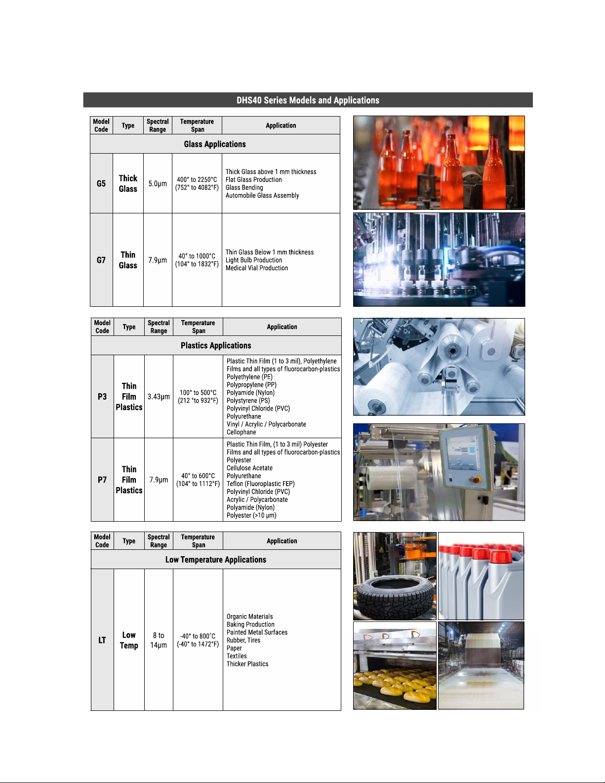
DHS40 Product Line................................................................................................................................................ 6
Principle of Operation ................................................................................................................................................ 8
Basics of Infrared Thermometry ............................................................................................................................ 8
Target Ratio............................................................................................................................................................ 9
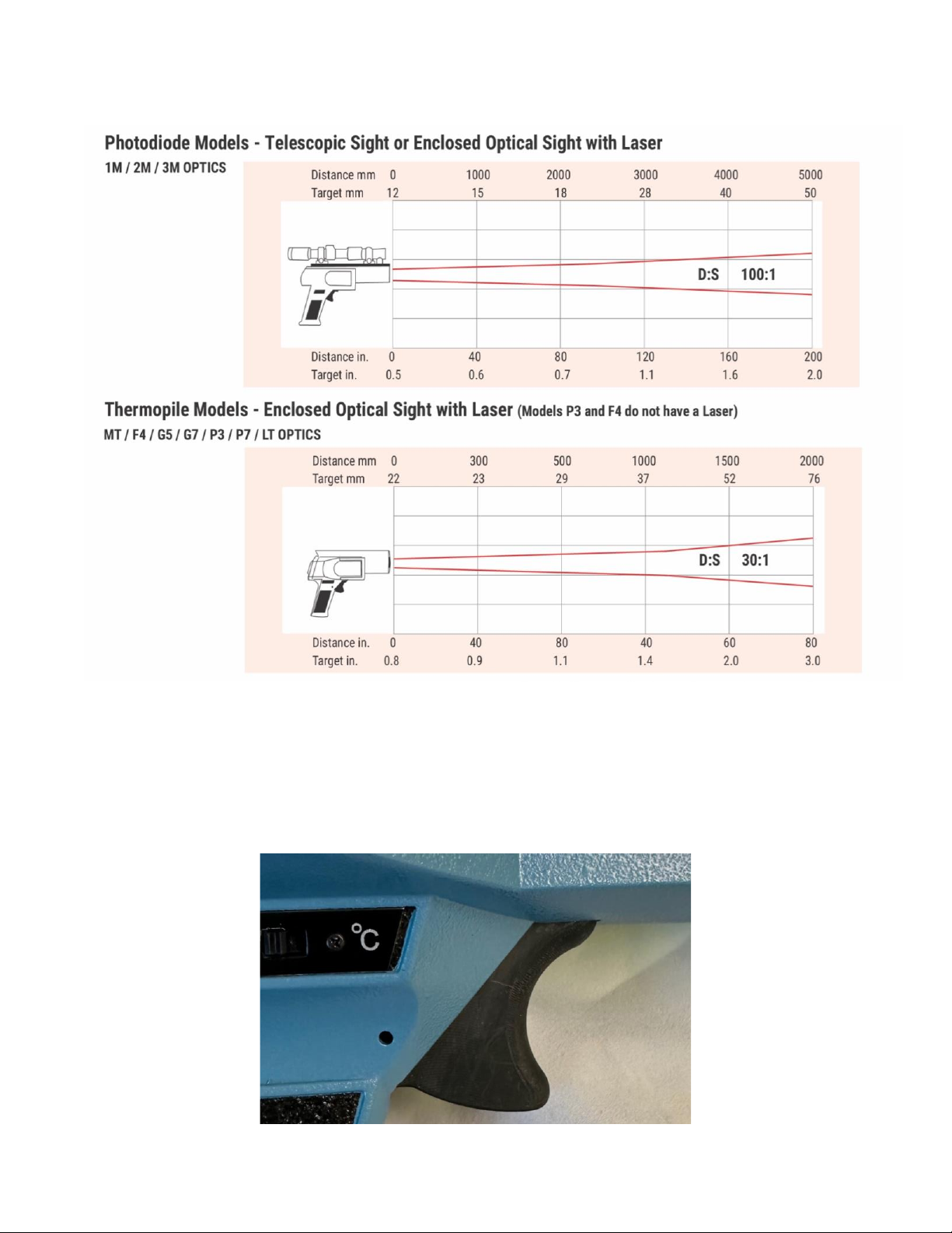
DHS40 Optics Diagrams........................................................................................................................................ 10
DHS40 Features.................................................................................................................................................... 10
Trigger .............................................................................................................................................................. 10
LCD Display ICONS............................................................................................................................................ 11
Control Panel.................................................................................................................................................... 13
°F / °C Switch .................................................................................................................................................... 14
Laser Switch...................................................................................................................................................... 14
Laser ................................................................................................................................................................. 15
Laser Specifications .......................................................................................................................................... 15
Caution .................................................................................................................................................. 15
Optical Sight ..................................................................................................................................................... 15
Telescopic Sight................................................................................................................................................ 16
Tri-Pod Connection........................................................................................................................................... 16
Trigger Lock ...................................................................................................................................................... 16
Power Source ................................................................................................................................................... 17
Emissivity.............................................................................................................................................................. 17
Typical Emissivity Values.................................................................................................................................. 18
Maintenance and Troubleshooting...................................................................................................................... 19
Return for Calibration Service.............................................................................................................................. 19
Appendix I: Emissivity of Common Materials .......................................................................................................... 20

DHS40 Series High Performance Hand-Held Infrared Sensors User Manual
3
Hints for Choosing and Using ........................................................................................................................... 20
How it works......................................................................................................................................................... 20
When to use ......................................................................................................................................................... 20
Temperature at a distance............................................................................................................................... 20
Temperature of Moving Material .................................................................................................................... 20
Temperature of Small, Low Mass Material ...................................................................................................... 21
Temperature of Areas too Hot for Personnel .................................................................................................. 21
Temperature of Rough Surfaces ...................................................................................................................... 21
Temperature Requiring Quick Measurement.................................................................................................. 21
Emissivity Table .................................................................................................................................................... 22
Metals............................................................................................................................................................... 22
Non-Metals....................................................................................................................................................... 23
Thank you for purchasing a Wahl High Performance Hand-Held Infrared Thermometer.
We appreciate your business.

DHS40 Series High Performance Hand-Held Infrared Sensors User Manual
4
Heat Spy Warranty
Manufacturer warrants all Wahl Heat Spy Fixed Infrareds manufactured by us to be free from defects in material
or workmanship under normal use and service. The Manufacturer agrees to repair or replace any product listed
above which upon examination is revealed to have been defective due to faulty workmanship or material if
returned to our factory, transportation charges prepaid, within the product specific warranty period of two (2)
years from date of purchase. This warranty is in lieu of all other warranties, expressed or implied and of all
obligations or liabilities on its part for damages including but not limited to normal wear and tear or consequential
damages following the use or misuse of this or any instrument sold by the Manufacturer. In addition, if the product
is tampered with in any way or calibrated in any way other than by the instructions supplied by Palmer Wahl, it
will immediately void the warranty. No agent is authorized to assume, for the manufacturer, any liability except
as set forth above. Freight cost to return item(s) for evaluation, duties and other fees are not covered by the
manufacturer.
Product is automatically registered for warranty by serial number at time of purchase. Serial number must
remain attached to product upon return.
Safety Instructions
This document contains important information and should be kept with the instrument at all times during its
operational life. Other users of this instrument should be given these instructions with the instrument. Future
updates to this information can be found at www.wahlheatspy.com and must be added to the original
document. The instrument can only be operated by trained personnel in accordance with these instructions and
local safety regulations.
Acceptable Operation
This instrument is intended only for the measurement of temperature. The instrument is appropriate for
continuous use and operates reliably in demanding conditions, such as in high environmental temperatures, as
long as the documented technical specifications for all instrument components are adhered to. Compliance with
the operating instructions is necessary to ensure the expected results.
Unacceptable Operation
This instrument should not be used for medical diagnosis.
Replacement Parts and Accessories: Use only original parts and accessories approved by the manufacturer. The
use of other products can compromise the operation, safety, and functionality of the instrument.
Instrument Disposal
Disposal of old instruments should be handled according to professional and environmental regulations of your
area for electronic waste.
Laser Warning
The instrument could be equipped with a Class 2 laser. Class 2 lasers shine only within
a visible area at an intensity of 1 mW. The laser functions only to locate and mark
surface measurement targets. Do not aim the laser at people or animals.
DO NOT AIM THE LASER AT THE EYE AS EYE DAMAGE WILL RESULT.

DHS40 Series High Performance Hand-Held Infrared Sensors User Manual
5
Includes
The DHS40 comes included with 9V Alkaline Battery (PN:12232), Trigger Lock (PN:9852), Carrying Case (PN:
12423-04), Certificate of Conformance (on packing slip), and user manual (available for download).
DHS40 Specifications
High Performance Hand-Held Infrared
MEASURING
SPECIFICATIONS
Model Numbers
1M / 2M / 3M
MT / F4 / G5 / G7 / P7 / LT
P3
Optical
100:1
30:1
30:1
Accuracy 1
± 0.25% of reading
or ± 1°C
± 0.6% of reading or ± 1°C
± 0.6% of reading
or ± 1°C
Repeatability 2
± 0.10% of reading
± 0.30% of reading
± 0.30% of reading
LCD Resolution
1°F / 1°C
1°F / 1°C
1°F / 1°C
Response Time 3
5 mS
150 mS
750 mS
Emissivity
0.10 to 1.00
0.10 to 1.00
0.10 to 1.00
ELECTRONIC
SPECIFICATIONS
Display
LCD with Back Light, 128 x 64 DOT
Keyboard
4 - Key - MENU, UP, DOWN, ENTER
Alarm
High or Low
Signal Processing
MAX / MIN / AVG / Delta T / Temperature
SENSOR
SPECIFICATIONS
Ambient Temperature
0° to 50°C (32° to 122°F)
Storage Temperature
-20° to 70°C (-4° to 158°F)
Relative Humidity
10% to 95% non-condensing
POWER
Power Supply
9 V DC Battery
Battery Life
30 hours, approximately
ENCLOSURE
Housing Material
Aluminum
EMI Interference
Designed for Maximum EMI and RFI Protection
Housing Dimensions /
Weight
13 x 6 x 15.5 in (330.2 x 152.4 x 393.7mm) / 2.2 lbs. (0.99 kg)
1at ambient temperature 23°C, ε =1.0, NIST transfer standard.
2at ambient temperature 23°C.
390% of value.
The Wahl DHS40 conforms to RoHS requirements
according to EU Directive (EU) 2015/863- amending
Annex II to Directive 2011/65/EU for restriction of
Hazardous substances.

DHS40 Series High Performance Hand-Held Infrared Sensors User Manual
6
DHS40 Product Line

DHS40 Series High Performance Hand-Held Infrared Sensors User Manual
7

DHS40 Series High Performance Hand-Held Infrared Sensors User Manual
8
Principle of Operation
DHS40 Series Hand-held-IR sensors use a modular structure and component interchangeability to ensure an
instrument is ideally suited for each particular application. It also simplifies field troubleshooting, repair and
calibration.
Basics of Infrared Thermometry
Every object emits some amount of infrared radiation. As the object temperature increases, the intensity of the
radiated energy increases. This emitted energy is related to a term called emissivity which is a number between
0 and 1 which is the object emitted energy in relation to a black body perfect radiator. A perfect radiator has an
emissivity of 1 meaning that all the energy being emitted belongs to it whereas the measured target of interest
may have part of its emitted energy being reflected from something else. We want to factor out the reflected
energy by selecting a correct emissivity setting. The emissivity of most common materials is known, either
exactly or closely as some objects will vary due to age and cleanliness. See more information about emissivity
and a table of values for common materials in Appendix I.
Detector
Thermopile
A thermopile is a tight cluster of a large number of tiny specialized thermocouples. They are connected together
to form a single measuring point and the output is the difference between the ambient temperature the head
electronics are in (the cold junction) and the target temperature collected and determined by the optical system
wavelength filter and the thermopile (hot junction).
The waveband is determined by an additional optical filter chosen by the manufacturer for the specific
application. This is to reduce or eliminate emitted wavelengths, which might belong to the target or might be
unwanted reflections that are of no interest for the measurement application.
Wahl provides six (6) different spectrums in our thermopile versions. They are 3.43 micron, 3.9 micron, 4.11 to
4.72 micron, 5.0 micron, 7.9 micron and 8 to 14 micron.
Photodiode
Both Silicon and InGaAs photodiode principles are completely different from thermopile: the collected energy is
transformed into electron flow. The result is a current proportional with the incident energy.
This transformation is very fast, taking only a few µS. The response time of the measuring system is limited by
the electronics; high resolution and low energy consumption makes it a little bit slower. The waveband is
determined by the physical characteristic of the sensor.
Wahl provides three (3) different spectrums in our photodiode versions, 1.0 micron, 1.6 micron and 2.4 micron.
Lens and Filter
The specifications of the lens decisively determine the optical path of the infrared thermometer, characterized
by the ratio Distance to Spot size. The spectral filter selects the wavelength range, which is relevant for the

DHS40 Series High Performance Hand-Held Infrared Sensors User Manual
9
temperature measurement. The detector and the processing electronics transform the emitted infrared
radiation into electrical signals.
Target Ratio
The actual area being measured is determined by the distance-to-spot ratio of the model you are using; this
varies from model to model. As the distance from the object being measured increases, the spot size of the area
being measured also increases.
Wahl provides two (2) optics options for the DHS40 model, one (1) for both the photodiode and one (1) for the
thermopile versions.
Maximum Distance and Spot Size
Use the size of the object being measured, together with the optical resolution of the infrared thermometer to
determine the maximum distance between the two. The object being measured should completely fill the field
of view of the optics to prevent any potential errors.
Proper Placement of Sensor:
To achieve the best results, the spot size of the infrared thermometer should be smaller than the object being
measured.
Before using, review the target to ratio tables on the following pages for the appropriate Optics image for your
model to determine the correct distance and visual field.
Target greater than spot size
Target equal to spot size
Target smaller than spot size

DHS40 Series High Performance Hand-Held Infrared Sensors User Manual
10
DHS40 Optics Diagrams
DHS40 Features
Trigger
The trigger is contoured to fit the index finger. This is a single position trigger, which turns the instrument on
when pulled. The display will show blank for a fraction of a second before the first reading appears to allow the
microprocessor to complete its initial calculation cycles.

DHS40 Series High Performance Hand-Held Infrared Sensors User Manual
11
LCD Display ICONS
Emissivity Setting
Transmission Setting
Backlight On/Off
Alarm Low

DHS40 Series High Performance Hand-Held Infrared Sensors User Manual
12
Alarm High
°F or °C
Hold Symbol
Battery Status

DHS40 Series High Performance Hand-Held Infrared Sensors User Manual
13
LCD Display ICONS
Name
Symbol
Note
Emissivity
ɛ= x.xx
See pg. Emissivity section and Appendix I
Transmission
T = x.xx
Setting for 1M and 2M model, thru windows
Glass: 0.92
Quartz: 0.88
Back Light
BLIGHT
ON or OFF
Alarm Low
ALM LO
XXXX
OFF
If ON: 4-digits will be display for setting value
Alarm High
ALM HI
XXXX
OFF
If ON: 4-digits will be display for setting value
C / F
C or F
Switch between °C / °F by use of the switch on the side of the
unit
Hold
H
After trigger is released, all info on LCD will remain for 8 seconds
Battery Status
BAT Symbol
Control Panel
4-Button: MENU / UP / DOWN / ENTER
When Trigger is Pressed
Far Left Button
Center Left Button
Center Right Button
Far Right Button
MENU
↑
↓
⏎

DHS40 Series High Performance Hand-Held Infrared Sensors User Manual
14
During Measuring (Default)
Far Left Button
Center Left Button
Center Right Button
Far Right Button
Entering measuring mode
Scrolling MAX/MIN/AVG/DEL in second temperature display
⏎
During Setting
Press “Menu” Button to enter Setting Mode
Far Left Button
Center Left Button
Center Right Button
Far Right Button
Emissivity
Increase Value
Decrease Value
Set Emissivity up to 2 digits
Transmission
Increase Value
Decrease Value
Set Transmission up to 2 digits
Back Light
Increase Brightness
Decrease Brightness
High Alarm
Increase Value
Decrease Value
Set High Alarm up to 4 digits
Low Alarm
Increase Value
Decrease Value
Set Low Alarm up to 4 digits
Press “Menu” Button to Save the Setting and proceed to the next setting
When Trigger is Released
Display will be held for 8 seconds
°F / °C Switch
The user can switch between °F and °C at any time. The real time reading will be changed instantly.
Laser Switch
All DHS40 models (except P3 and F4 models) include laser sighting.

DHS40 Series High Performance Hand-Held Infrared Sensors User Manual
15
Laser
The laser beam defines the center of the target to be measured by projecting a spot of high intensity red light on
the target surface. Note that the entire surface area to be measured is larger in diameter than the spot
illuminated by the laser. If desired, look through the enclosed optical sight to determine the entire diameter of
the target.
The laser beam will not affect temperature readings. The beam will appear brightest in indoor light and dim in
outdoor light. The enclosed optical sight is more effective in outdoor lighting conditions.
To activate laser sighting, turn on the laser power switch located on the left side of the DHS40 in the area just
above the handle. Squeeze the trigger to activate the laser beam; release the trigger to deactivate.
To save battery life, turn off the laser power switch after use.
Laser Specifications
Power output: 1mW maximum
Wave length: 660 nm
Useful range: 100 feet (indoors)
Caution
DO NOT AIM THE LASER AT THE EYE AS EYE DAMAGE WILL RESULT.
AVOID REFLECTIONS FROM SHINY OBJECTS SUCH AS MIRRORS, BRIGHT METAL AND GLASS.
THE REFLECTED LASER LIGHT IS JUST AS DANGEROUS AS THE DIRECT BEAM.
Optical Sight
The enclosed optical sighting system used in the DHS40 allows precise aiming at the required target field of view
with compensation for parallax. What you see in the sight is the center of the spot you are measuring. Two
circles are utilized on the optical sighting system, one marked 4 and the other marked 20. These correspond to
exact target alignment at 4 and 20 feet and correct for parallax offset.

DHS40 Series High Performance Hand-Held Infrared Sensors User Manual
16
Telescopic Sight
The telescopic sighting system used in the DHS40 allows precise aiming at a longer distance, or when measuring
targets at higher temperatures. A filter in the lens reduces the glare from high heat, allowing for accurate
temperature measurement of the required target.
Tri-Pod Connection
Standard threaded tri-pod mount is located in the base of the handle for tri-pod mounting which can be used to
hold the DHS40 in one position for real time temperature reading.
Trigger Lock
At times, particularly for recording or calibrating, it is useful to mechanically lock the trigger in the pressed
position. The DHS40 is designed to permit insertion of a pin in the housing and trigger to lock it in the "ON"
position. A locking pin is supplied, but any 0.040 inch wire or pin can be used for this purpose. (Locking Pin PN:
9852)

DHS40 Series High Performance Hand-Held Infrared Sensors User Manual
17
Power Source
The DHS40 is powered by a standard 9V type alkaline battery (Wahl PN: 12232). This battery is located in the
handle, and is easily replaced. Normally, the battery supplied has 500 milliamp hours, providing about 140 hours
of continuous duty. The battery is connected to the system with snap on clips which are polarized. When the
battery cover is removed, a spring will push the battery out for easy access.
Emissivity
Emissivity in infrared (IR) measurement refers to the ability of the surface being measured to emit radiation.
Surfaces vary in emissivity and this must be taken into account before accurate readings can be obtained. The
emissivity ratio represents the amount of radiated energy that the measured surface returns to the instrument.
A return of 100% of the energy is measured as 1.0 emissivity. If all the radiated energy is reflected and/or
transmitted and none emitted, the emissivity ratio is 0.0. A perfect radiator such as a black body, has a 1.0
emissivity ratio and a very shiny or highly-polished surface has a ratio of 0.2 or lower. Most textured or painted
surfaces have an emissivity ratio of around 0.95. DHS40 Series Wahl Heat Spy thermometers feature adjustable
emissivity from 0.10 to 1.00.
One of three things will happen to the energy as it reaches the sensor:
E - Emitted Energy - Some energy will be absorbed and converted into heat.
R - Reflected Energy - Some energy will be reflected from the surface of the material.
T - Transmitted Energy - Some energy will be transmitted completely through the material.
As one or more of these three things must happen to the energy, the amount of energy absorbed, reflected
and transmitted must add up to 100%. Therefore, the coefficients of absorption, reflection and transmission
(E, R, and T) must equal 1.

DHS40 Series High Performance Hand-Held Infrared Sensors User Manual
18
The ideal material in non-contact temperature measurement and, in fact, the source against which instruments
are calibrated is the black body. This is defined as a surface which emits the maximum amount of radiation at a
given temperature. The name "black body" is misleading because it implies color - the color of the material is
not as important as the surface finish. Materials which are good radiators (absorbers) and approximate black
body conditions are carbon, asbestos, and rubber. Highly polished metals are poor black bodies and therefore
good reflectors.
As long as the emissivity setting on the instrument is properly set with respect to the material being measured,
all measurements with the infrared thermometer will be precise.
The emissivity can be determined by one of the following methods, in order of preference:
1.
Determine the actual temperature of the material using a sensor such as a RTD, thermocouple or
another suitable method. Next, measure the object temperature and adjust the emissivity setting until
the correct value is reached. This is the correct emissivity for the measured material.
2.
For relatively low temperature objects (up to 260°C or 500°F), place a piece of tape, such as a masking
tape, on the object. Make sure the tape is large enough to cover the field of view. Next, measure the
tape temperature using an emissivity setting of 0.95. Finally, measure an adjacent area on the object
and adjust the emissivity setting until the same temperature is reached. This is the correct emissivity for
the measured material.
3.
If a portion of the surface of the object can be coated, use a flat black paint, which will have an emissivity
of about 0.98. Next, measure the painted area using an emissivity setting of 0.98. Finally, measure an
adjacent area on the object and adjust the emissivity setting until the same temperature is reached. This
is the correct emissivity for the measured material.
Typical Emissivity Values
The table in Appendix I provides a brief reference guide to determine emissivity and can be used when one of
the above methods is not practical. Emissivity values shown in the table are only approximate, since several
parameters may affect the emissivity of an object. These include the following ones:
1.
Temperature
2.
Angle of Measurement
3.
Geometry (plane, concave, convex, etc.)
4.
Thickness
5.
Surface Quality (polished, rough, oxidized, sandblasted)
6.
Spectral region of measurement
7.
Transmissivity (e.g., thin film plastics)
To optimize surface temperature measurements, consider the following guidelines
1.
Determine the object emissivity using the instrument to be used for the measurement.
2.
Avoid reflections by shielding the object from surrounding high temperature sources.
3.
For higher temperature objects, use the shortest wavelength instrument for your temperature range.
4.
For semi-transparent materials such as plastic films and glasses, ensure that the background is uniform
and lower in temperature than the object.
5.
Mount or hold the sensor perpendicular to the surface whenever the emissivity is less than 0.90. In any
case, do not exceed angles more than 30 degrees from incidence.

DHS40 Series High Performance Hand-Held Infrared Sensors User Manual
19
Maintenance and Troubleshooting
Each DHS40 is factory calibrated and certified against Wahl Standards. A NIST Certificate of Conformance stating
the nominal and actual values and the deviation error is available separately. The instrument calibration must be
periodically verified.
The DHS40 uses sophisticated analog and digital technology. All maintenance operations must be carried out by
qualified personnel.
For the instrument to function correctly the optic system must be kept clean. The maintenance department
should periodically check the unit and clean the lens.
Return for Calibration Service
To receive a NIST Traceable Certificate of Conformance or repair service on your product, go to palmerwahl.com
and click on: Request an RMA (Return Material Authorization Number) and follow the instructions. You will
receive your RMA number via email once your item is received at our facility. If you prefer, call Customer Service
at: 1-800-421-2853 for assistance with the RMA process. Material being returned to us should be packed well,
preferably in the original shipping container.
Our quality management system is certified to conform to ISO 9001:2015. We maintain a calibration system in
conformance with ANSI/NCSL Z-540 and MIL-STD-45662A.
All calibrations are performed against standard instruments, traceable to NIST. Records are stored for a
minimum of three years. Standards used have a test ratio of four times greater than the unit being calibrated.
We can perform certified, traceable calibrations in support of companies that require meeting FAA and FDA
quality standards.
Palmer Wahl Instruments, Inc.
234 Old Weaverville Road
Asheville, NC 28804
Phone: 800-421-2853 • 828-658-3131
FAX: 828-658-0728
Email: [email protected]
www.palmerwahl.com
CALIBRATION

DHS40 Series High Performance Hand-Held Infrared Sensors User Manual
20
Appendix I: Emissivity of Common Materials
Hints for Choosing and Using
Know Your Target
What is the material? How clear is the optical (IR) path to the target? Are reflections a concern? What is the
expected temperature range you will need to measure?
Know Your Spot Size
The target must completely fill the sensitive area in order to get accurate readings.
Have Realistic Expectations
If you need to know the temperature within 1 degree Fahrenheit, you should use another technology, like a RTD
contact probe.
Stabilization
Allow the IR thermometer to stabilize at the temperature where it will be used for at least 30 minutes for an
accurate reading.
Keep the Lens Clean
Also watch out for dusty or vapor-filled optical paths.
Accuracy Concerns
If accuracy is a concern, use a model with adjustable emissivity. If you’re just looking for “hot spots” a fixed
emissivity model will work well.
Always Remember
You are only measuring surface temperature. If you need the temperature of a mixture, use an immersion probe
and an electronic thermometer.
How it works
All solid objects emit infrared energy above absolute zero. The amount of energy emitted is proportional to the
body temperature. Wahl’s DHS40 directs this energy by means of fixed focus optics into a sensitive detector,
which is amplified and processed by the computer to temperature readings in °F or °C. It is fast, because IR
energy travels at the speed of light, and the detector has a very low mass. The time constant is 0.1 second,
about 10 times faster than conventional contact methods. Measurements are displayed in less than one second.
When to use
Temperature at a distance
You can stand 1 to 40 feet away and conveniently measure temperature of bearings, kilns, and furnace walls.
You can locate hot spots in reactor shells, steam piping, and insulation surfaces. Specialty models can be used to
up to 300 feet away from your temperature target.
Temperature of Moving Material
Moving materials require two DHS40 features not available by any other temperature measuring methods: non-
contact with the process material, and fast-measurement of rapidly moving materials. Measure continuously
This manual suits for next models
10
Other Wahl Thermometer manuals

Wahl
Wahl 2500MX User manual

Wahl
Wahl DHS 520 User manual

Wahl
Wahl TM612 User manual

Wahl
Wahl Heat-Prober 392AHP User manual

Wahl
Wahl Digi-Stem DST600 Series User manual

Wahl
Wahl DHS235XEL User manual

Wahl
Wahl HEAT-Prober 392HP User manual

Wahl
Wahl Heat Spy DHS520 User manual

Wahl
Wahl 2500MVX User manual

Wahl
Wahl Digi-Stem User manual