Wahlberg 320.704 User manual

WWW.WAHLBERG.DK JENS JUULS VEJ 1
TELEPHONE: +45 86 18 14 20 8260 VIBY
EMAIL: sales@wahlberg.dk DENMARK
Remote Controlled Platform Series
Item No. 320.704 (Off-Road), No. 320.703 (Standard) and
No. 320.702 (Low Height)
User Manual

320.805.004 2 Date: 2022-02-09
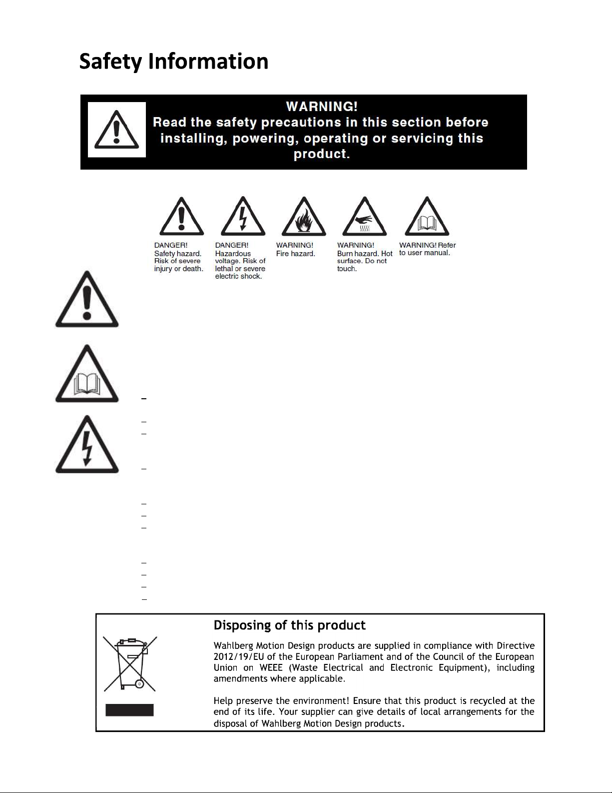
The following symbols are used to identify important safety information on the product an in this manual:
This product is for professional use only. It is not for household use.
This product presents risks for severe injury or death due to fire hazards, electric shock, and falls.
Read this manual before installing, powering or servicing the product; follow the safety precautions listed
below and observe all warnings in this manual and printed on the product. If you have questions about how
to operate the product safely, please contact you Wahlberg Motion Design supplier or Wahlberg Motion
Design. Use only genuine Wahlberg Motion Design parts or parts approved by Wahlberg Motion Design.
PROTECTION FROM ELECTRIC SHOCK
Before using the product, check that all power distribution equipment and cables are in perfect
condition and rated for the current requirements of all connected devices.
Select a suitable power plug converter supplied with the product.
Isolate the battery and charger from power immediately if any seal, cover, cable, or other
component is damaged, defective, deformed, wet, or showing signs of overheating. Do not reapply
power until repairs have been completed.
Refer any service operation not described in this manual to a qualified technician.
PROTECTION FROM BURNS AND FIRE
Do not operate the product if the ambient temperature (Ta) exceeds 40° C (104° F).
The exterior of the motors becomes warm during use. Avoid contact by persons and materials.
Do not modify the product in any way not described in this manual.
PROTECTION FROM INJURY
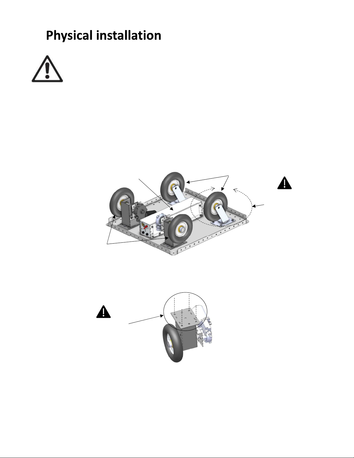
Always secure the load on the platform and make sure it is within the weight limit and centered.
Ensure that the surface is flat and clean before using the platform.
Always install the product as described in this manual.
Do not operate the product with missing or damaged covers, or shields.
Disposing of this product
Wahlberg Motion Design products are supplied in compliance with Directive
2012/19/EU of the European Parliament and of the Council of the European
Union on WEEE (Waste Electrical and Electronic Equipment), including
amendments where applicable.
Help preserve the environment! Ensure that this product is recycled at the
end of its life. Your supplier can give details of local arrangements for the
disposal of Wahlberg Motion Design products.

320.805.004 3 Date: 2022-02-09
SAFETY INFORMATION 1
INDEX 3
TECHNICAL SPECIFICATIONS 4
DRAWING 5
INTRODUCTION 6
PACKAGE CONTENT ...................................................................................................................................... 6
DESCRIPTION............................................................................................................................................... 6
AREA OF USE ............................................................................................................................................... 7
USING FOR THE FIRST TIME ............................................................................................................................ 7
TRANSPORT ................................................................................................................................................ 7
PHYSICAL INSTALLATION 8
FASTENING THE MOTOR BRACKET, BATTERY PACK AND CASTOR WHEEL TO AN OBJECT .............................................. 8
AC POWER 10
VOLTAGE .................................................................................................................................................. 10
POWER PLUG ............................................................................................................................................ 10
RADIO CONTROL 10
TIPS FOR RELIABLE RADIO TRANSMISSION ....................................................................................................... 10
SETUP 11
MOUNTING THE LOAD ................................................................................................................................ 11
USING THE REMOTE.................................................................................................................................... 12
SPEED, RAMP AND SYSTEM SETTINGS (FACTORY DEFAULTS) ............................................................................... 13
ADJUSTING THE TRIMS ................................................................................................................................ 14
CONNECTING THE PLATFORM ....................................................................................................................... 15
FAIL-SAFE SETTING ..................................................................................................................................... 17
DUTY-CYCLE .............................................................................................................................................. 17
SERVICE AND MAINTENANCE 18
SPARE PARTS ............................................................................................................................................. 18
ON-SITE SERVICE ........................................................................................................................................ 18
CHARGING ................................................................................................................................................ 18
REMOTE BATTERIES .................................................................................................................................... 18
PLATFORM BATTERIES ................................................................................................................................. 19
MAINTENANCE PLAN .................................................................................................................................. 19
CHECKLIST ................................................................................................................................................ 19
APPENDIX 3 - BLOCK DIAGRAM 20

320.805.004 4 Date: 2022-02-09
Model: Remote Controlled Platform Series
Item no.: 320
Dimensions: (L×W) 700 × 700 mm (27.56 x 27.56 in.) and optional 1000 x
1000 mm (39.37 x 39.37 in) or customized on request
Platform battery: 2x 12V 12AH
Charger for platform: 100-240 V AC 50-60 Hz 50VA, EU/UK/US/AUS plug
Charger for remote: 100-240 V AC 50-60 Hz Flash 8 only
Charging time: 24 hours, optional rapid charger 1.5 hour
Off-Road platform (320.704)
Height: 240mm (9.5 in)
Moving speed (No load): 2.0 m/s or 7.2 km/t (6.5 ft/s or 4.4 mph)
Maximum Load: 200 kg (440.9 lb)
Wheel: 200 mm (7.9 in)
Standard platform (320.703)
Height: 160mm (6.3 in)
Moving speed (No load): 1.2 m/s or 4.5 km/t (4.1 ft/s or 2.8 mph)
Maximum Load: 300 kg (661.4 lb)
Wheel: 125 mm (4.9 in)
Low Height platform (320.702)
Height: 132mm (5.0 in)
Moving speed (No load): 0.4 m/s or 1.4 km/t (1.3 ft/s or 0.9 mph)
Maximum Load: 150 kg (330.6 lb)
Wheel: 100 mm (3.9 in)
Transmitter: Digital RC, 2.4 GHz band
Range: 100 m (300 ft)
Ambient temperature: 5-40°C (41-104°F)
Weight: 29 kg (63.9 lb) for 700x700 mm
Duty-cycle: 50% when running more than 60 min.

320.805.004 5 Date: 2022-02-09
Remote Controlled Platform Series (320)
Item No. 320.704 (Off-Road)
Item No. 320.703 (Standard)
Item No. 320.702 (Low Height)

320.805.004 6 Date: 2022-02-09
Thank you for selecting the remote-controlled platform, a wireless controlled motor system from
Wahlberg Motion Design. Before using the Wahlberg Motion Design product for the first time,
please read this manual carefully. Failure in handling can cause injury of persons and/or damage
the motors.
Package content
1× Platform with motor units and battery pack incl. receiver unit
1× Remote controller Hitec Flash 7 or 8, or AT9S Pro
2x 12V Charger for platform (standard version)
2x 2 cell Li-Fe battery for remote 6.4V 1400mAh (Flash 8 only)
1x Charger for Remote (Flash 8 only)
4x Standard AA Alkaline battery for remote (Flash 7 only)
8x Standard AA Alkaline battery for remote (AT9s Pro only)
1x User Manual
Description
Smart and easy controlled moving platform for running stenographic elements, actors or
Musicians on stage. The platform comes in 3 different versions with Off-Road, Standard or Low
Height wheels, consisting of two separate motor brackets where the drive wheels is mounted.
The battery pack and motor bracket can easily be moved to a custom-made platform with 4 screws
and a little creativity.
Safety functions
The control system ensures that the motor is only powered when:
The wireless signal is reliable.
The motor is instructed to move.
No overload.
The product should only be operated by an experienced operator. And the product must be used
according to the manual. The platform will stop whenever the transmitter is powered off, or if the
signal is lost, as well as when the power switch is turned off on the platform.

320.805.004 7 Date: 2022-02-09
Area of use
WARNING! When running the platform, the surface must be hard and flat.
WARNING! To reduce the risk of electric shock or injury: use charger indoors only
WARNING! To reduce the risk of electric shock, do not expose charger to rain: store indoors!
The platform itself is intended for indoor and partly outdoor use. It is designed to move
stenographic elements, actors or Musicians on the stage at the speed stated in "Technical Data".
Any other use of the product may result in a risk of injury of persons or equipment damage.
Exceeding the load rating may cause failure of the equipment.
Do not modify the product. For any modification of your product, contact Wahlberg Motion
Design.
It is the customers' responsibility that any local restrictions concerning the use of the product are
fulfilled.
Using for the first time
Important! The product must be protected from environmental factors such as physical shocks
and vibration during transportation and storage.
WARNING 2 before installing, powering, operating, or
servicing the product. Before applying power to product:
Check the Wahlberg Motion Design website at www.wahlberg.dk for the most recent
documentation and technical information about the Remote-Controlled Platform. Wahlberg
Motion Design user manual revisions are identified by the revision number in the bottom of
each page.
2.
Check that the local AC mains power source is within the rated power voltage and frequency
ranges for the chargers.
Transport
Important! The product must be protected from environmental factors such as physical shocks
and vibration during transportation.
Use only the original packaging, flight case, or pallet frame for protecting the product during
transport. Contact Wahlberg Motion Design for enquiries regarding flight cases or pallet frames.

320.805.004 8 Date: 2022-02-09
WARNING! Make sure each motor bracket, battery pack and castor wheel are secured with
minimum four bolts or screws to a stable platform.
WARNING! Make sure both drive wheels and castor wheels can move freely in any direction.
Fastening the motor bracket, battery pack and castor wheel to an object
The standard product comes with each component securely mounted on a rectangular platform,
but in some situations, you may desire to fasten each part from the existing platform directly to
an object.
The drive wheels and castor wheels must be placed in the same order like on the supplied platform
and they should also be positioned at each corner of an object for proper stability, however more
castor wheels may be added in order to secure an irregular object.
Wooden objects may be fixed with a suitable screw, otherwise bolts with lock nut or washer is
needed to fix each part. Carefully test that both drive wheels and castor wheels can move freely
in any direction. The battery pack should also have enough free space to the floor to avoid collision
with obstacles.
Make sure the motor cabling is secured and kept away from the wheels and the floor, in case the
wiring needs to be extended use minimum 1.0mm2 (AWG 18) and maintain the existing polarity
for correct function of the product.
Castor wheels
Drive
wheels
Battery pack
Use minimum four
bolts or screws for
each part
Secure free
movement in
any direction

320.805.004 9 Date: 2022-02-09
The standard motor cabling is approx. 80cm (31 in) the following connections will apply.
Wire Device
Blue wire (- on forward) to upper tap (4.8mm)
Left motor (turning right on forward)
404.386 (off-road and standard motor)
Orange wire (+ on forward)
to lower tap (6.3mm)
Green wire (+ on forward)
to lower tap (6.3mm)
Right motor (turning left on forward)
404.385 (off-road and standard motor)
B
rown wire (
-
on forward)
to upper tap (4.8mm)
Seen from the bottom the connections will look like the below picture.
Figure 1: Motor connections
Right motor #404.385
Left motor #404.386

320.805.004 10 Date: 2022-02-09
WARNING 2 before connecting AC mains power to the
charger.
Voltage
WARNING! Check that the voltage range specified on the charger matches the local AC mains
power voltage before applying power to the charger.
Power plug
The charger unit comes with four changeable power plugs and contact your local electrician for
another converter if needed.
WARNING! This equipment can cause radio interference, make sure this equipment respects
all national and local regulations before use.
CAUSION: Change or modifications not expressly approved by the party responsible for
A standard RC transmitter and receiver is used to control the motors, and there is no manual or
other control options available.
The radio device uses the 2.4 GHz band as accepted in Europe and USA. For other locations and
national restrictions consult your national authority, like in France there are specific frequency
ranges required 2.4056 GHz 2.4482 GHz.
FCC Notice
This device complies with Part 15 of the FCC Rules. Operation is subject to the following two
conditions: (1) This device may not cause harmful interference, and (2) this device must accept
any interference received, including interference that may cause an undesired operation.
Tips for reliable radio transmission
Do a range check before each live event, and make sure the range limitation is not exceeded.
Know your batteries condition, keep both remote and platform charged.
Always use the Fail- -
Power off unused wireless devices -
during use.

320.805.004 11 Date: 2022-02-09
WARNING! Rea 2 before installing, powering, operating, or
servicing the product.
WARNING! Only experienced users should operate the product. Contact Wahlberg Motion
Design for further information and education on motion equipment.
WARNING! Make sure the object is secured on the platform and that the weight is within the
limit, centered and does not make the platform unstable during acceleration and
deacceleration.
WARNING! Mounting screws and bolts through the platform shall be kept away from the drive
and castor wheels.
Mounting the load
The standard products will have mounting holes along each side of the platform [A] and minimum
one screw at each corner or side is recommended. The screws for drive motors, castor wheels and
battery pack [B] should not be unscrewed.
The object on the platform must be centered and within the weight limitation for each variant as
specified, also considerations for a low center of gravity will be needed depending on the shape
and dimensions of the object.
A
B
Do not unscrew!
8mm (0.31 in)
bolt or screw
through 4mm
(0.16 in) steel
Maximum load (see
technical specifications)
and secure a low center
of gravity
The object should
not exceed the size
of the platform

320.805.004 12 Date: 2022-02-09
Model-1 Opti&Mini
NONAME-1
Check your situation.
ready to transmit?
Yes No
Using the remote
WARNING! Make sure the Right Gimbal J1/J2 is in the centre position before turning ON the
platform.
For using the remote RadioLink AT9S Pro see page 16.
The remote and the platform has been paired together at the manufacturing facility and the
product is ready for use. For guidance on changing the maximum speed and acceleration
/deceleration ramp see page 13.
The unit has a lot of controls not being used for this application and these may be left is any
position, meaning that this will not affect the behaviour of the platform when using the factory
defaults explained in this manual, the below Figure 2 will identify the specific controls needed
for operation.
Figure 2: Flash 7 Remote (Flash 8)
Power on
Power on the remote using the [On/Off Switch] and turn down the left throttle joystick [Left
Gimbal J3/J4] and the display will show.
Use the [Jog Dial] to select [Yes] if not already highlighted and then press Enter [Jog Dial] when
you are ready to continue.
T1/T2

320.805.004 13 Date: 2022-02-09
You may now power on the platform by turning the power switch to the ON position, see Figure
3 below.
Finally, the platform can easily be moved around by holding the remote with one hand if desired.
And moving the right gimbal will control the speed and direction seen from the back of the
platform as shown below.
Figure 3: Platform seen from the back
Moving the gimbal forward and backward will move the platform forward and backwards, and in
the same manner the platform will turn right and left when moving the gimbal to the right and
left side.
Speed, ramp and system settings (Factory defaults)
The following settings has been programmed into the remote by Wahlberg Motion Design, so this
guideline is for customized setup and reprogramming in case settings are lost or critical parts are
replaced. Using the menu, you may need to change the following parameters in each sub menu.
Enter the [Acro.List] list by press and hold the [Jog Dial] button only.
Sub menu Parameter Setting Note
E P A
(Maximum
Speed)
CH1 AILE
L/U R/D
100 100 This parameter controls the maximum
speed of the platform by a value in the
range of 30-125. All four values must be
identical to maintain uniform control.
WARNING! Changing this parameter may
lead to re-adjusting the [Right Gimbal
Trims] to keep the platform from moving
when the joystick is centred.
CH2 ELEV L/U R/D
100 100
S.Speec
(Acceleration /
deacceleration
ramp)
CH1 AILE:
0.5 This parameter controls the ramp when
starting a movement by a value in the
range of 0.5-2.0. Both values must be
identical to maintain a uniform control.
WARNING! Setting the ramp too low may
damage the motor gears if you quickly
make a stop or change direction with
heavy loads.
CH2 ELEV: 0.5
Reverse CH1 AILE: REV Control setting (Hold Jog Dial pressed for
changing the setting)
CH2 ELEV: NOR Default.
Right gimbal on remote

320.805.004 14 Date: 2022-02-09
Enter the [System.List] by press and hold the [Back] button while pushing the [Jog Dial] button.
Sub menu Parameter Setting Note
Management BACKLIGHT
Always Off For maximum battery life set the backlight
off and turn it on in low light situations.
UI FEEDBACK
Off To avoid the beep sound, like in theatres
or similar locations.
Mode STICK MODE 2 Default.
MDL Type TYPE
ACRO Default.
WING
DELTA
(
ELE
VON)
2AILE Control setting.
Note: Make sure to select the correct
2AILE mode called DELTA(ELEVON)
shown in the settings.
Adjusting the trims
As a starting point the right gimbal indicators in the display, see Figure 4 should both be set in the
centre position by using the right gimbal trim T1 and T2, see Figure 2.
Figure 4: Flash 7 Remote Display (Flash 8)
If the platform is still moving when the right gimbal (Joystick) is centred, you will need to correct
the offset by first adjusting the T2 until only one of the drive wheels are moving, and then T1 until
both drive wheels are in a static position. For easier identification the drive wheels may be lifted
from the floor during this procedure.
Trim centered

320.805.004 15 Date: 2022-02-09
[Binding] Opti&Mini
Optima
Minima
[Binding] Opti&Mini
Do you want to bind?
(Radio stop]
Yes No
[Binding] Optima
Press and hold the
link button on the
receiver and turn on
the power
NEXT
[Binding] Optima
Reboot RX & check that
all functions
if correct,
Press [Finish]
Finish
Connecting the platform
Enter the [System.List] by press and hold the [Back] button while pushing the [Jog Dial] button.
Sub menu Parameter Setting Note
Spectra RECEIVER
Opti&Mini
System setting.
When the above setting is selected, scroll down to the [BINDING] and press enter using the [Jog
Dial] and the display will show.
Highlight the [Optima] and press [Enter], the display will show.
Press [Yes] and follow the instructions shown below.
To access the link button, you will need to remove the cover on the battery pack.
Figure 5: Receiver unit OPTIMA 7 (OPTIMA 9)
Press and hold the Link button [A] on the receiver by using a suitable screwdriver or similar and
turn on the power switch on the platform [B). The display will show the following when succeeded.
Press Enter [Jog Dial] and check that the Fail-safe function is working, see page 17.
Link button [
A
]
Power switch [B]
C]

320.805.004 16 Date: 2022-02-09
Using the remote AT9S Pro
The AT9S Pro is a different remote control. It is not compatible with the Optima receivers and
therefore the original remote control type should be used. Although the remote looks advance
the platform will run out of the box simply my moving the right joystick.
All other controls are for adjustment purposes. The remote control uses 8 AA batteries.
Connecting the platform
Note that the platform and accompanied remote are connected by default. Should they
disconnect do the following
1. Access the receiver by removing the cover of the battery pack on the platform.
2. Hold the remote close to the receiver (max 50 cm).
3. Click and hold the ID button on the receiver near
the ON/OFF Power Switch of the platform.
4. The LED on the receiver will flash. When it stops
flashing the remote and platform are connected.
Menu options
Navigating the menu: Hold MODE for 1 second to enter menu, navigate using the Dial, enter menu
points by pressing the PUSH button and exit them pressing the END button. Switch between Basic
menu and Advanced menu by pressing the MODE Button.
To enter the menu the remote must be on the home screen as seen above. Change home screen
by pressing the END Button.
Non-default settings: *ADVANCED MENU
- PARAMETER SOUND: OFF
- MODEL TYPE Type: ACRO, AILE-2: CH6&5, ATL: OFF
- END POINT 1:AILE 140/140, 2:ELEV 140/140 Lower values for slower top speed
- REVERSE 1:AILE REV, 2:ELEV NOR
- *ELEVON MIX:ACT
- *SERVO DLY 1:AILE 0%, 2:ELEV 0% Increase for faster acceleration
When you receive the platform, the remote is trimmed meaning it will run straight forwards when
the joystick is pushed straight forwards. Depending on the load on the platform this may change.
Use the Elevator Trim Lever and Aileron Trim Lever to compensate if necessary.

320.805.004 17 Date: 2022-02-09
Fail-safe setting
WARNING: The Fail-safe must be activated and set correctly for safe operation!
When the trim has been adjusted so there is no movement when the right gimbal is in the centre
position, the fail-safe can be set by pressing the Link button [A] for about 6 seconds until the red
LED[C] goes off, see Figure 5.
When releasing the Link button [A] within the following 2 seconds C] will start flashing
red/blue for a few seconds, so make sure to keep the right gimbal in the centre position until the
Finally, the platform must be repowered in order to store the new fail-safe settings, and the safety
function should be tested by lifting the drive wheels from the surface, set any direction and speed,
then power off the remote and the drive wheels must come to a stop within a second or so. The
procedure must be repeated if this is not the situation.
Duty-cycle
When the unit is continually operated for more than 60 minutes at full load, speed and high
ambient temperatures, a duty-cycle (DC) limitation of 50% will need to be considered.
The duty-cycle (DC) is the fraction of a period where the motor is active. The duty-cycle is
commonly expressed as a percentage or ratio. Its described as the period it takes for a system to
complete an on-and-off cycle.
Thus, a 10% duty-cycle means the system is on 10% of the time and off 90% of the time
for a duty-cycle is normally related with a cycle length in time. E.g. a max duty-cycle of 50%
(30 min. ON / 30 min. OFF), means that the motor may not be active for more than 30 minutes
every hour, or after 5s ON the motor must be OFF for 5s if continually operated for more than 60
minutes.

320.805.004 18 Date: 2022-02-09
WARNING 2 before servicing the product.
WARNING! Turn off the power switch on the platform and allow cooling down for at least 10
minutes before handling.
WARNING! Refer any service operation not described in this user manual to a qualified service
technician.
ATTENTION! Interval of inspections should be determined according to the frequency of use and
the working scenario of the product.
ATTENTION! Signs of malfunction or poor operation should always lead to an inspection of the
product.
Spare parts
Only parts ordered at or approved by Wahlberg Motion Design should be used in the product to
ensure correct function and stability. Contact Wahlberg Motion Design to inquire about spare
parts.
On-site service
On-site service and maintenance can be provided by the Wahlberg Motion Design, giving owners
access to Wahlberg Motion expertise and product knowledge in a partnership that will
ensure the highest level of performance throughout the
Wahlberg Motion Design for details.
Charging
A charge of the platform will usually take about 24 hours with the included charger, and 1½ hour
with a rapid charger (ordered separately).
Also keep the charger connected when the product is not in use for a longer period, and make
sure the batteries is fully charged before disconnecting the charger, as this will extend the lifetime
of Lead-acid batteries on storage.
The Flash 8 remote can be charged by using the supplied charger, and this charger does not need
to be connected if the product is on storage for a longer time.
Remote batteries
The Flash 7 remote comes with 4xAA Alkaline batteries and can simply be replaced by removing
the back cover on the remote controller.
The Flash 8 remote comes with rechargeable Li-Fe batteries included and replacement is not
needed before end of battery life, contact Wahlberg Motion Design for suitable replacement
batteries.
The AT9S Pro remote comes with 8xAA Alkaline batteries and can simply be replaced by removing
the back cover on the remote controller.
For both Flash 7 & Flash 8 the battery voltage can be monitored on the remote display and the
warning threshold for standard Alkaline batteries is 4.0V (Flash 7) and 6.0V for Li-Fe (Flash 8).

320.805.004 19 Date: 2022-02-09
Platform batteries
Internal Lead-acid batteries on the platform are maintenance free, and the product can be stored
in any orientation, contact Wahlberg Motion Design for suitable replacement batteries and for
further information on when and how to replace the batteries.
Maintenance plan
The results of all the regular inspections are to be documented and kept available at the company.
The written result of the last inspection must be kept available at the site of operation, e.g. by an
inspection sticker on the product the date of the inspection, the basis of the inspection and the
name of the inspector.
Before every use and weekly
Every time when the product is prepared for the event, before running the platform and at
least every week when the product is in use:
Object safety mounted on platform
Batteries fully charged
Transmitter range
Monthly
At regular intervals but at least every month when the product is in use:
Check that the battery pack, drive motors and castor wheels for damages and proper
fastening.
Change damaged parts according to this manual.
Yearly
The product must be inspected by a specialist every 12 months.
Every 48 months
The product should be inspected by an authorised expert every 48 months.
Checklist
Use the checklist accordingly; before each use, each month etc.
Check Type Result
Battery pack, drive and castor wheels are
mounted correctly and secured with four
screws each
Inspection
Object mounted safely on platform Inspection
Check transmitter range Testing
Battery voltage on remote Inspection
Battery voltage on receiver Inspection
Check battery status and level on charger Inspection

320.805.004 20 Date: 2022-02-09
Input/output
Receiver
Block diagram of the remote-controlled platform.
Power in
12V
Charging
XLR 4 Pole
Battery
charger
12VDC
(External)
Motor controller
Battery
2x12VDC
12AH
Fused
2xT16A
Gear M
Gear
M
Power
switch
Left
Drive wheel
Right
Drive wheel
2.4GHz
Band
+5V
+24V
Remote controller
Power in
100-240V~
Multiplug
Power out
12V
Charging
XLR 4 Pole
This manual suits for next models
2
Table of contents
Other Wahlberg Winch manuals

Wahlberg
Wahlberg 50 Series User manual

Wahlberg
Wahlberg 380 User manual

Wahlberg
Wahlberg Winch 10 Cable User manual

Wahlberg
Wahlberg Winch 25 User manual

Wahlberg
Wahlberg Winch 10 Cable User manual

Wahlberg
Wahlberg 239.701 User manual

Wahlberg
Wahlberg Winch 10 User manual

Wahlberg
Wahlberg 245 Winch 50 User manual

Wahlberg
Wahlberg Winch 25 User manual