Wallgate SNC-02 User manual

Product Manual
SNC-02 Ceiling Mounted
Shower Head

Revision 3
2
SNC-02 Product Manual

Revision 3
3
SNC-02 Product Manual
Table of Contents
1. Disclaimer ..........................................................................................................................4
2. Conventions .......................................................................................................................5
2.1 Warning............................................................................................................................5
2.2 Note .................................................................................................................................5
2.3 Numbered procedures......................................................................................................5
2.4 Bullet lists........................................................................................................................5
2.5 Menu items.......................................................................................................................5
3. Glossary.............................................................................................................................6
4. Overview............................................................................................................................6
5. Package Contents..............................................................................................................7
5.1 Mounting Guidelines.........................................................................................................7
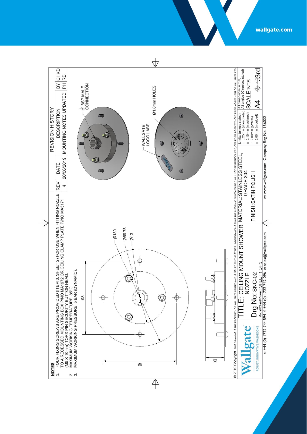
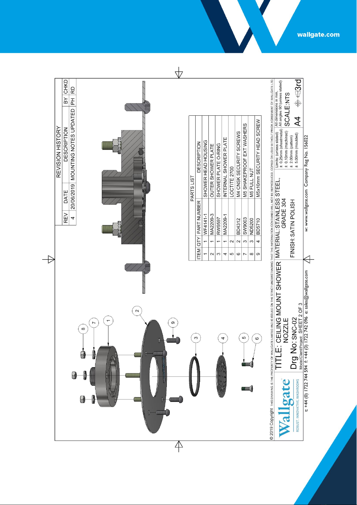
5.2 Ceiling Mounted Shower Installation.................................................................................8
5.2.2 Method 1: Cast Concrete Ceiling Mounted ..................................................................11
5.2.3 Method 2: Fixing Box...................................................................................................13
5.2.4 Method 3: Cast in Box .................................................................................................15
5.2.5 Method 4: Clamping Plate ...........................................................................................17
5.3 Water Connections.........................................................................................................18
5.4 Ceiling Shower Spray Pattern.........................................................................................19
5.5 Commissioning for Use ..................................................................................................21
5.6 Technical Specifications.................................................................................................21
6. User and Maintenance Instructions ..................................................................................21
6.1 Operation .......................................................................................................................22
6.2 Maintenance...................................................................................................................22
6.3 Spare Parts List..............................................................................................................23
7. Related Documentation....................................................................................................23

Revision 3
4
SNC-02 Product Manual
1. Disclaimer
Every effort has been made to supply information within this manual which is correct.
Wallgate Limited will not be liable for any damage or loss that arises if the person
installing, operating or maintaining the unit has not read or not complied with the
manual.
In any event, and without prejudice to any warranties in Wallgate Limited’s terms and
conditions of sale, Wallgate Limited’s liability for all damages and losses (including
negligence) shall not in any circumstances exceed the amount paid by the customer
for the shower head.
Wallgate reserves the right to alter, update or improve its product specification at any
time without prior notice. This manual is specific to the product that it has been
supplied with at the date of supply.
Without prejudice to any warranties in Wallgate Limited’s terms and conditions of
sale, any warranty will be invalidated if the equipment is installed or serviced by
unqualified personnel.
No part of this publication and the information contained may be reproduced,
transmitted, stored in a retrieval system, used or disclosed wholly or partly without
prior written permission from Wallgate Limited.
For full warranty details please see Wallgate Limited Terms and Conditions.
Please ensure this manual is passed to the end user. The manual forms an integral
part of the product and should be kept for its working life. Additional copies of this
and other supporting documents are available by contacting Wallgate Ltd or by
visiting www.wallgate.com

Revision 3
5
SNC-02 Product Manual
2. Conventions
Certain conventions are used in this manual to make it easier to read and
understand. They are given in the sections below.
2.1 Warning
A warning with red text on a white background is used to give information about
hazards that can cause injury or death. Read and understand these warnings before
you install and commission the shower. Failure to heed these warnings can have
serious consequences.
WARNING! This is a warning!
2.2 Note
A note with yellow text on a white background is used to draw your attention to
important and useful information.
NOTE: This is a note.
2.3 Numbered procedures
Steps in procedures are numbered, starting from 1.
1. This is step 1.
2. This is step 2 etc.
2.4 Bullet lists
•A bullet list is used to give information that is not sequential.
2.5 Menu items
Menu items, submenu items, and settings, where available, are given in bold.

Revision 3
6
SNC-02 Product Manual
3. Glossary
The glossary lists all words, abbreviations and technical terminology used in this
manual, along with a short description of these terms.
Term
Description
TMV
Thermostatic mixer valve controls and maintains a mix of
hot and cold-water temperature for safety and prevention
possible scalding.
Anti-Ligature
Recently we have become aware that there is some
inconsistency in the market as to the exact meaning of
"anti-ligature". When we use this phrase about our
products it means that we have designed and tested the
product to reduce any risk of that product being used as
a ligature attachment point.
BSP
The British Standard Pipe (BSP) thread is a family of
standard screw thread types that has been adopted
internationally for interconnecting and sealing pipe ends
by mating an external (male) with an internal (female)
thread.1
4. Overview
This product is an anti-ligature and highly robust stainless-steel flush fitting ceiling
mounted shower head with anti-ligature/anti-tamper fixings and front facing
removable shower plate.
1
Description sourced from Wikipedia at http://en.wikipedia.org/wiki/British_standard_pipe_thread Description

Revision 3
7
SNC-02 Product Manual
5. Package Contents
Before you begin the installation, make sure that you have the following items:
✓1x Product manual
✓1x SNC-02 Ceiling Mounted Shower Head.
✓4x M5 Security Screws
✓1x ½” BSPP Female to 1/2'' NPT Male (the US only)
NOTE: An electronic control unit, activation sensor and solenoid water valves
with cables are supplied separately. Various other control options are
available, contact the Wallgate sales for more information.
5.1 Mounting Guidelines
•The ceiling shower nozzle must be mounted to a flat surface.
•The nozzle must be fed by a blended supply that complies with the regulatory
standards, set to the necessary temperature range(s). If a TMV is used it must be
positioned before a solenoid valve.
•Measure, mark and cut aperture for the plate housing and fixings (as shown in
figure 3, 4, 5 or 6 depending on fixing method).
•A mounting box is available for recessed precast concrete or fabricated ceiling
mounting. Contact the Wallgate sales desk for more information.

Revision 3
8
SNC-02 Product Manual
5.2 Ceiling Mounted Shower Installation.
NOTE: The ceiling mounted shower requires installation following the
guidelines in figures 3 - 6 depending on the mounting method.
NOTE: The following examples refer to the use of Hilti HUS3 masonry screws
for a concrete ceiling. Refer to Hilti data sheet for full installation instructions
of fixing system. If other fixings systems are used, refer to the manufacturer's
literature for torque settings. Tighten sufficiently to prevent removal without
tooling.
NOTE: Exceeding the torque setting for the M5 screws can result in damage to
the mounting plate.
NOTE: It is recommended to apply anti-pick hard set mastic to shower nozzle
plate edges against the wall, (i.e. Sikadur 33).

Revision 3
9
SNC-02 Product Manual
Figure 1: Ceiling mounted shower head.

Revision 3
10
SNC-02 Product Manual
Figure 2: Ceiling mount shower head exploded view.

Revision 3
11
SNC-02 Product Manual
5.2.2 Method 1: Cast Concrete Ceiling Mounted
(See Figure 3):
1. Create ø80mm clearance hole in the ceiling.
2. Mark fixing hole location with the shower head as a reference.
3. Use 4x pan head, security fixing screws suitable for concrete ceiling material (not
supplied) to fix the shower head to the ceiling (e.g. Hilti HUS3 6mm concrete
screw anchors). Drill ceiling holes as detailed in Hilti data sheet and then retain
plate to the ceiling using installation torque of 25Nm. For alternative fixing
systems, refer to fixing manufacturer’s guidance for torque settings.
4. Ensure the plate is flush against the ceiling to maintain anti-ligature and vandal
properties.

Revision 3
12
SNC-02 Product Manual
Figure 3: Ceiling mounted shower head installation (Method 1).

Revision 3
13
SNC-02 Product Manual
5.2.3 Method 2: Fixing Box
(See Figure 4):
1. Create 85mmx85mm clearance hole in the ceiling.
2. Create ø120mm x 2mm recess for the nozzle box flanges.
3. Using the mounting box as a reference, mark 4x ø6.5mm clearance holes for the
threaded fixings on the back box.
4. Use 8x pan head, security fixing screws suitable for concrete ceiling material (not
supplied) to fix the shower head to the ceiling (e.g. Hilti HUS3 6mm concrete
screw anchors). Drill ceiling holes as detailed in Hilti data sheet and then retain
plate to the ceiling using installation torque of 25Nm. For alternative fixing
systems, refer to fixing manufacturer’s guidance for torque settings.
5. Fit the 4 x M5 screws (Item 3, Fig: 2) through shower plate into ceiling mounting
box. Tighten each screw to a torque of 3.5Nm, a thread lock can be applied
(Loctite 222).

Revision 3
14
SNC-02 Product Manual
Figure 4: Ceiling mounted shower head installation with fixing box (Method 2).

Revision 3
15
SNC-02 Product Manual
5.2.4 Method 3: Cast in Box
(See Figure 5):
1. Cast ceiling mounting box into ceiling ensuring flanges are flush with the ceiling.
NOTE: Box size: 80x80x65mm.
2. Fit the 4 x M5 screws (Item 3, Fig: 2) through shower plate into ceiling mounting
box. Tighten each screw to a torque of 3.5Nm, a thread lock can be applied
(Loctite 222).

Revision 3
16
SNC-02 Product Manual
Figure 5: Ceiling mounted shower head installation with a cast in box (Method 3).

Revision 3
17
SNC-02 Product Manual
5.2.5 Method 4: Clamping Plate
(See Figure 6):
1. Create ø80mm clearance hole in the ceiling.
2. Offer shower plate up to opening and mark 4x fixing points.
3. Drill 4x holes to a suitable clearance diameter for M5 machine screws.
4. Fit 4 x M5 button head security screws with a suitable length to pass through
ceiling thickness into ceiling clamping plate. Tighten each screw to a torque of
3.5Nm, a thread lock can be applied (Loctite 222).

Revision 3
18
SNC-02 Product Manual
Figure 6: Ceiling mounted shower head installation clamping plate (Method 4).

Revision 3
19
SNC-02 Product Manual
5.3 Water Connections
NOTE: Before you carry out the following steps, flush the water supply pipes to
remove any debris and trapped air.
NOTE: Fit a Y strainer in the water supply feed pipes prior to connection of
solenoid valve, especially on older installations where loose particles from
ageing water pipes can cause a blockage and/or damage to the outlet or
solenoid valves.
NOTE: The shower nozzle must be fed by a blended supply that complies with
the regulatory standards, set to the necessary temperature range(s). If a TMV is
used it must be positioned before a solenoid valve.
NOTE: Use of any pipe sealing compound should be avoided to prevent
blockages and damage to the shower nozzle and water solenoid valves.
NOTE: It is recommended to fit a service isolating tap on the water supply feed
before solenoid valve. This allows for ease of maintenance when required. The
isolating taps are not supplied by Wallgate and should be purchased
separately.
1. Connect ½” BSP female fitting to male ½” BSP thread on shower nozzle
housing.
2. Figures 3, 4 and 5 are for illustration only, installation should be made in
accordance with site-specific plumbing requirements.
5.4 Ceiling Shower Spray Pattern
The ceiling shower will have varying spray pattern dimensions depending on
mounting height and water flow rate. Figure 7 on the following page has a table
indicating the various spray diameters at two different flow rates, 6lpm and 8lpm.

Revision 3
20
SNC-02 Product Manual
Figure 7: Ceiling shower spray pattern.
Table of contents
Other Wallgate Bathroom Fixture manuals
Popular Bathroom Fixture manuals by other brands

antoniolupi
antoniolupi MYSLOT 72 installation instructions

Triton
Triton unichrome Series Installation and operating instructions

SMEDBO
SMEDBO SELF-AD Mounting instructions

Kohler
Kohler 76399T installation instructions

Franke
Franke RODAN RODX677 Installation and operating instructions

Glacier bay
Glacier bay HD58303-3701 Use and care guide

Panasonic
Panasonic DH-4UD1 Operating and installation instructions

Uberhaus
Uberhaus 70845000-01-02-03 Operator's manual

Artweger
Artweger 360 9WTS Series Assembly instructions

RAVAK
RAVAK VS 3 100 installation instructions

FORENO
FORENO NORTH NRT73RBB installation instructions

Aquatica Digital
Aquatica Digital Spring RC-300/140 Installation & Care Manual