Walthers Cornerstone 933-4600 User manual

HO Structure Kit
BLAST FURNACE
933-4600
© 2020 Wm. K. Walthers, Inc., Milwaukee, WI 53218 waltherscornerstone.com I-933-4602 Printed In China
Thanks for purchasing this Cornerstone® kit! Please take a few minutes to read the instructions and study the drawings before
starting each step. While this is a large kit, each step can be completed in stages: work slowly and highlight or check off each
completed assembly sequence. All parts are made of styrene, so use only compatible glue and paint to assemble and finish your
model. You may find it easier to build and paint some parts as subassemblies before moving on to the next step. PLEASE
NOTE: Most individual part numbers are molded on sprues, however some sprues have been trimmed; please refer to illustra-
tions to properly identify parts.
While no other structure is so closely associated with a steel works, blast furnaces actually produce “pig iron.” Named for an
early casting method resembling a mother pig nursing little ones molten iron flowed into a large main trench called the “sow,”
then into several smaller trenches, where it cooled to form “pigs.” Once charged and “blown in,” the furnaces run non-stop at
temperatures up to 3500°F (1926.7°C). Each ton of pig iron produced requires about three tons (2.7t) of raw materials: nearly
two tons (1.8t) of ore, about 1500 pounds (0.6804t) of coke and the rest in fluxing stone (usually limestone or dolomite), plus a
few hundred pounds of iron and steel scrap. Finally, four (3.6t) to four-and-one-half tons (4.0t) of air will be consumed. For every
ton of iron, 700 pounds (317k) of slag (a lava-like material reclaimed for sale to the construction industry) and six tons (5.4t) of
gases are produced. And since part of the charge is always melting, voids are created that have to be refilled constantly.
Meeting this voracious appetite is the job of the ore yard, where huge quantities of raw materials arrive by boat (ore carriers,
despite their size, are known as “boats” on the Great Lakes) and rail. Materials are transported from here to the furnaces in older
open hopper cars and ore jennies on an elevated stretch of two or three parallel tracks known as the “highline.” Running behind
the furnace, the tracks span storage bins where coke, scale, scrap, dolomite, ore and limestone are kept ready.
Raw materials for the charge (or burden) enter the furnace through the top via conveyors at newer facilities, or in a pair of
wheeled carts called skip cars fed by a bridge crane, that constantly ride up and down on steeply pitched rails. As one skip
loads, the other is emptied at the top.
The “blast” in a blast furnace comes from the blowing engine house; here giant air compressors pressurize the cold blast main,
a huge pipe feeding air into three or more heated and refractory-lined stoves to raise the temperature to 1800°F (982.2°C). This
superheated air is fed under pressure into the furnaces via a bigger pipe known as the hot blast main. So there’s a constant
supply of air available, the process rotates through each stove with one on blast, one heating and one on standby.
Once combustion begins, the hot air blast forces the coke in the charge to burn faster producing more heat, and large amounts
of carbon monoxide and other reducing gases that are also burned. For each ton of iron, there may be 100 to 300 pounds (100-
136k) of flue dust suspended in this gas, which is rich in iron and coke particles and reclaimed for use. This begins at the top of
the furnace, where four offtakes resembling huge upside down slingshots converge into a single downcomer. This feeds gas
into a dust catcher, capturing large dry particles like a vacuum cleaner in a holding bin. The gas then passes through sprays of
water inside a gas washer and a precipitator to capture progressively smaller particles, with the resulting slurry pumped to a
settling operation, where solids settle to the bottom. From here, the dust and slurry are sent to a sintering plant (dust in old
covered hoppers, slurry via pipelines) where it’s pressed into large pellets that are sent back to the furnaces.
The heart of the furnace is the hearth at the bottom, where molten iron and slag collect. Two or three hours before the iron is
tapped, slag is drawn off. More will be removed about an hour before the cast, and the balance is tapped with the iron. When
the iron is ready, a clay plug in the bottom of the hearth is drilled open. Molten iron then flows into a refractory-lined iron runner
on the floor of the cast house, essentially a large covered platform with open sides and ends to dissipate heat, and into smaller
runners loading hot metal cars for the trip to the converters, where the impurities will be burned out to create molten steel, or
slag cars which dump their loads in an open pit some distance away.
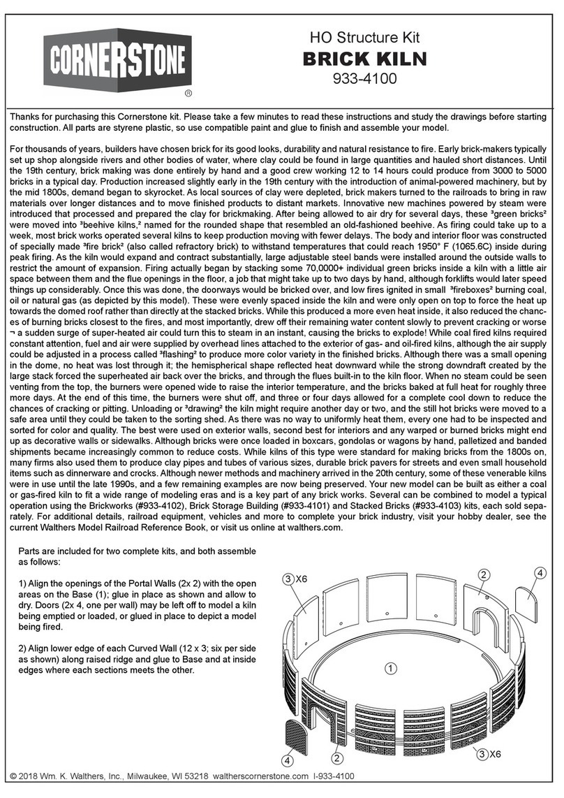
The centerpiece of your steel works, you can easily model a complete operation with the Blowing Engine House with Piping
Extensions (#933-4602), along with the WalthersProto® Hot Metal Bottle Car 2-Packs (#920-107900 Gray or #920-107901
Rust) and Slag Car 2-Packs (#920-1079010 Gray or #920-107911 Rust) and Bridge Crane (#933-2906). For more models,
photos and information on Walthers Steel Series, visit your participating hobby shop, see the latest Walthers Model Railroad
Reference Book or visit us online at walthers/products/steel-series.
PLEASE NOTE: As individual part numbers are molded on a sprue that has been trimmed , please
refer to the illustrations to properly identify parts.
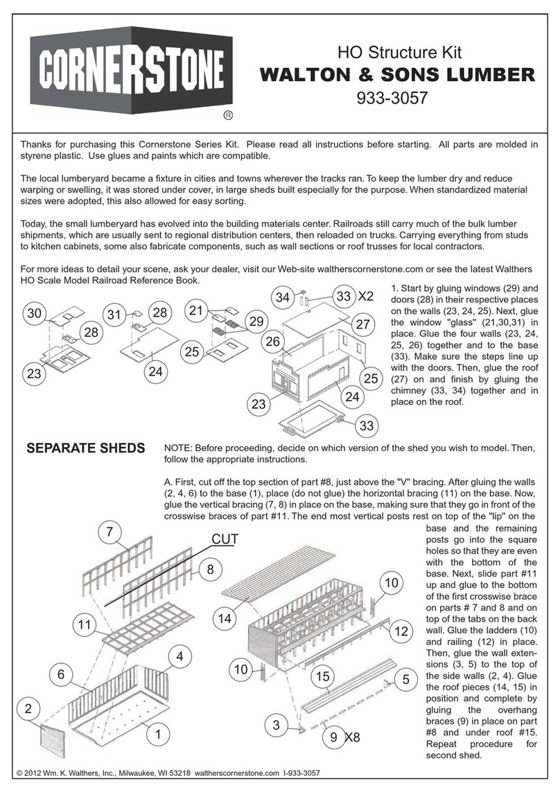
Figure 1
Figure 2
FURNACE ASSEMBLY
PLEASE NOTE: To help identify and install parts in steps 11 to 14 refer to Figure One
for placement of individual pieces, and Figure Three showing finished assembly.
FIGURE ONE
1) Glue Bustle Pipes (2x 48, 3x 49, 3x 49A) together to form a circle.
2) Remove outside beveled edge on Mantle Ring (40).
3) Trim 0.01969 (0.5mm) from flat back half of Bustle Pipe Hangers (6x 50). Align
curved edge downward as shown; glue Hangers to top (side without arrows) of Mantle
Ring.
4) PLEASE NOTE: When assembling the Mantle Ring, be sure one arrow on the ring
points to the pipe inlet; turn Mantle Ring upside down and glue Bustle Pipe to Hangers.
5) Glue Furnace Halves (2x 43) together and set – DO NOT GLUE - assembly in circular
opening in Base (142) to align parts. When dry, slide the Mantle Ring, up to the notch in
the bottom of the furnace. Align joint in Furnace Halves with arrows on bottom of Mantle
Ring and glue together.
6) Make four Lower Offtake assemblies by gluing Right (51) and Left (52) sides together
as shown. Glue completed Offtakes to four openings in top of Furnace. Align Bell
Platform (47) with Offtakes protruding through openings, with notch in platform to rear,
and Bustle Pipe Inlets to left as shown,
7) PLEASE NOTE: Two Platform Supports (63) will be installed in Step 66; using raised
ridges to align parts, glue six Platform Supports to underside of Bell Platform and to
Furnace as shown,
8) Use the “O” marks on the bottom of the Furnace to align the Tuyres (12x 41) and glue
to Bustle Pipe and Furnace.
9) Note: During assembly, align – DO NOT GLUE – lower ends of Mantle Columns (6x
42) in mounting points on Cast House Floor (#142); glue Mantle Columns to bottom of
Mantle Ring.
10) Glue Left (45) and Right (46) Bell Hopper halves together; align open side with rear
of Furnace and glue to top as shown.
11) Thread Sheaves (2x 68) on Sheave Rod (66) to stops. Insert ends of Rod into
bearings on top of Trolley Supports (2x 62) until flush with outside of bearings, and glue
in place.
12) Glue Small (70) and Large Bell Beam (69) to mounting points on Beam Support (64)
as shown. Glue Support assembly to top of Trolley Supports with the back of #64 3.93”
(100mm) from the front as shown.
13) Glue Braces (2x 65) on top front and back of Trolley Supports. Align Crane Beams
(2x 68) between mounting points on #64, and glue to top of Front Brace and Bell Beam
Support.
14) Align ends of Trolley Support with raised L-shaped ridges on Bell Platform (47) and
glue where parts meet.
15) Glue Platform Railings (236, 3x 237, 2x 238, 239 & 252) to edge of Platform as
shown.
16) Refer to Figure 2: Make two Upper
Offtakes by gluing (Left (53A) and Right (52)
Halves. Make two Offtake Elbows by gluing
Right (54) and Left (55) Halves together.
Glue Upper (157) to Lower (158) Down-
comer Pipe; glue Flange (159) to top end of
this assembly as shown.
17) Glue each Elbow assembly (54/55) to
Upper Offtake assembly (53/53A) at right
angles as shown. Insert – DO NOT GLUE –
each Upper into Lower Offtakes (from step
6). Insert – DO NOT GLUE – Downcomer
Top (157/158) between elbows.
18) With notch at rear as shown, glue
Platform (56) on top of Offtake Elbows. Align
all offtake piping from step 17 and glue loose
pieces together.
19. Glue Bleeder Valve Bases (2x 58) to
round locaters on Platform. With handles
facing front of furnace, glue Bleeder Valves
(2x 59) to top of each Base. Glue Large
Front and Rear Platform Railings (2x 57) to
Platform. Glue Small Railing (61) to left side
of Platform. Glue Top Brace (60) to top of
cross braces on Large Railings.

Figure 3
Figure 4
Figure 5
CAST HOUSE
FIGURE 4
20. Use raised ridges on Base (1) to align parts, and glue Left (2) Rear (3), Right (4) and
Front (5) Foundation Walls to Base and at inside corners where parts meet.
21) Note the correct alignment and use mounting points on Base to position Tall Outside
Columns (2x 11) and Short Inside Columns (2x 12) as shown behind Left Wall #2 and glue
where parts meet.
22) Align lower edge of Upper Rear Wall (7) along top of Rear Foundation walls, align
inside raised ridges with Tall Column, and glue where parts meet. Align lower edge of
Upper Right Wall (8) with top of Right Foundation Wall, and along inside corner of Upper
Wall, and glue where parts meet.
23) Glue Hoist House Columns (4x 10) to mounting points on Small Base (14). Glue Brick
Encasement Walls (4x 17 per column: 16 total) to Columns and at inside corners as
shown. Note the correct alignment and glue first Hoist House Column to outer raised
ridges on Upper Rear Wall. Glue Floor Supports (4x 149) on top of brick walls on front of
Hoist House and Support Columns and top of Right Foundation Wall.
FIGURE 5
PLEASE NOTE – some parts are omitted for clarity:
refer to Figure 6 for a fully assembled view. Each
Outside Base (2x 25) has five full column assemblies;
the Small Base (26) has four large Brick Encasements
installed from right to left, with a single partial Encase-
ment on the far left as shown.
24) Note the correct alignment and glue Cast House
End Columns (4x 13) to mounting points at outside left
and right ends of Large Bases (2x 25). Make four sets
of Large Brick Encasements by gluing Large End (2x 18
per column: 8 total) and Small Side (2x 19 per column:
8 total) Brick Walls to Base, Columns and at inside
corners as shown.
25) PLEASE NOTE: The center base will has two differ-
ent styles of brick encasements. From right to left as
shown, make four central encasements by gluing Small
Brick Encasement Walls (4x 17 per assembly: 16 total)
at inside corners and to raised mounting pads on Small
Base (26).
26) Assemble last encasement by gluing Left (20),
Right (21) and Inside (17) Brick Encasement Walls at
inside corners and to mounting pad at far left of Small
Base as shown.

Figure 6
27) Refer to Sketch 6 and align all three bases side-by-side; glue Exterior Floor Support Beams (3x 147)
inside of short columns to top of first two sets of Encasements at right, and last Encasement at left as
shown. Glue Interior Floor Beams (2x 148) to tops of remaining Encasements.
28) PLEASE NOTE: Test fit Pouring Spouts (8x 164) to mounting points along outside edges of Cast
House Floor (142); some filling may be needed due to the angles. When satisfied with the fit, glue Spouts
in place.
29) Insert columns at left through slots in Cast House Floor, with Floor resting on top of Foundation Walls.
30) Refer to Figure 7: glue Cast House Wall (6) to outside of columns and top of Foundation Wall (5).
Refer to Figure 6: insert Roof Supports (4x 38) through notches in Floor; glue to top of Encasements and
outside edges of Columns as shown.
31) Slide Cast House Columns through slots until Floor rests on
Support Beams, and glue where parts meet.
32) Glue Craneways (2x 37) to left and right top of inset (short) Cast
House Columns as shown.
33) Glue Left Side Cast House Floor Railings (213, 212, 211, 210,
209, 208, 2x 207, and 206) in place as shown. Carefully bend End
Railing (205) to fit angle of Floor and glue in place. Glue Right Side
Cast House Floor Railings (201, 2x 202, 203) in place as shown.
Glue End Rail (204) in place and to side rails where parts meet.

Figure 7
FIGURE 7
34) Insert Bustle Pipe inlet through opening in wall and glue completed Furnace above opening in Floor. Glue
Right (15) and Left (16) Hoist House Roofs to tops of walls around Furnace and at center where parts meet. Glue
Upper Side Wall (9) to tops of Hoist House Columns and underside of Left Roof.
35) Glue Cast House Roof Trusses (3x 27) to top of three middle Cast House Columns. Glue Clerestory Vent Side
Walls (2x 31) to outside edges of Trusses. Glue Left (29) and Right (30) Upper Cast House Side Walls to top of
Columns as shown. Glue End Wall (28) to outside edges of Side Walls and to Truss as shown.
36) Glue Lower Left (175), Upper Right and Left (2x 34) Cast House Roofs in place, and Left and Right Clerestory
Roof Halves (2x 36)

Figure 8
Figure 9
HOT BLAST STOVES
FIGURE 8
37) Glue Front (177), Rear (178) and Left and Right (2x 179) Side Walls
to Stove Base (176). Glue Stove Floor (77) top of base as shown.
38) Glue Lower Stack Halves (2x 127) together. Glue Front (105) and
Rear (106) Stack Breech Halves together. With holes facing down as
shown, insert – DO NOT GLUE – Breech into hole in Lower Stack. Make
three Stack Risers by gluing Right (3x 10⁷: one per stack) and Left (3x
108: one per stack) halves together. Insert - DO NOT GLUE – Stack
Risers into bottom holes of Stack Breech.
39) PLEASE NOTE: Starter points for inlets are molded on the back of
each Stove Half (6x 78); drill or cut each opening as follows: Rear of
Stove #1 only, drill out A. Rear of Stove 2 and 3, drill out B. Front of all
stoves, drill out C and D. Make three Stoves by gluing front and rear
halves together.
40) Refer to Figure 9: From left to right, glue Stoves 1, 2, and 3 on Floor
as shown. Test fit all stack piping from step 38 with inlets in Stoves: when
satisfied with fit, glue these parts in place.
41) Glue Upper Stack Halves (2x 128) together, insert lower end into top
of Lower Stack and glue where parts meet.
42) Use raised ridges to align
parts, glue Elevator Front Wall
(129) to Side Walls (3x 130) at
inside corners where parts meet
and to square mounting point on
right of Stove Base.
43) Align Stove Platform (132)
openings with caps on each Stove,
and below bottom doors of Eleva-
tor, and glue in place. Glue Rear
(224), Front (225) and End (223)
Railings to Platform.
44) Assemble three Safety Caged
Ladders by gluing Cage (3x 235:
one per assembly) to brackets on
Ladders (3x 234: one per assem-
bly). When dry, glue align tops of
Cage Ladders with openings in
Front Platform Handrail, and glue
where parts meet.
45) Assemble three Access
Platforms; from left to right, glue
Small Handrails (233, 227, 228,
229, 230, 231) to edge of Platform
(226); repeat for remaining two
Platforms. When dry, align below
ladders and glue to sides of each
Stove as shown in figure 10.

Figure 10
Figure 11
46) Glue End Pipe Supports (2x 110)
to mounting points at left of base.
47) Assemble three sets of Burner Feeds by gluing Left
(119) and Right (120) Halves together. Glue the upper
portion of each Burner into the D holes in each Stove.
Assemble three Burner Elbows by gluing Right (103)
and Left (104) Elbow Halves together. Glue Elbow
Flange (113) to front (long) end of each Burner Elbow.
Insert - DO NOT GLUE - Elbows into top of Burners.
48). Assemble three Lower Stove Valves by gluing Right (123) and
Left (124) Halves together. Glue pipe on lower end into C holes in
each Stove. Assemble three Upper Stove Valves by gluing Right
(121) and Left (122) Halves together. Glue Cap (125) to top of each
Upper Valve. Insert - DO NOT GLUE – Upper Valves into tops of
Lower Valves.
49) Align bottoms of Large Pipe Supports (3x 10⁹) with raised
squares on Base and glue together.
50) Glue Left (95) and Right (96) Halves of Clean Gas Elbow together.
Glue Lower (97) to Upper (98) Half of End Pipe. Glue Upper (99) to Lower
(100) Half of Clean Gas Pipe, Insert - DO NOT GLUE – Clean Gas Pipe
through openings at front of Large Pipe Supports. Align pipe outlets with
flanged end of Burner Elbows: when satisfied with the fit, glue parts
together. Glue Right (117) and Left (114) Clean Gas Pipe Flanges to ends
of Clean Gas Pipe. Set End Pipe in place on top of Small Pipe Supports.
Align outlet on End Pipe with Left Flange of Clean Gas Pipe and glue
where parts meet; glue End pipe in place. Glue End Pipe Flanges (2x
114) to outside ends as shown. Glue Clean Gas Elbow to front Flange as
shown. 51) Glue Upper (101) and Lower (102)
halves of Hot Blast Main together as
shown. Glue Right (116) and Left (112)
Flanges to ends of Hot Blast Main. Insert
- DO NOT GLUE – Hot Blast Main in
upper notches of Large Pipe Supports.
Align openings in Main with pipes in
Upper Stove Valves: when satisfied with
the fit, glue parts together.
52) Cut hole at marked locations on
inside of both Precipitator Halves (2x 82):
glue together. Glue Left (91) to Right (92)
Precipitator Pipe. PLEASE NOTE: Use
Coupling (111) to extend piping with parts
from the Blower Engine House (#933-
4602) or Blowing Engine House Piping Kit
(#933-4605), both sold separately, or Cap
(115). Align joints of Precipitator as shown
and glue Pipe to top. Align and glue
Precipitator Supports (4x 86) to under-
side. Refer to Figure 10: align small open-
ing on underside of Precipitator with End
Pipe Elbow, and glue Supports to mount-
ing points at far left of Stove Base.
53) Glue Right (81A) and Left (81) Gas Washer Halves together. Glue Valve Wheel
(87) to mounting point on Valve (84); glue mounting pin on top of Valve to opening in
Gas Washer as shown. Align and glue Gas Washer Supports (4x 85) to underside.
Glue Upper Right (93A) and Upper Left (93B) Washer Pipe together. Glue Lower Left
(94A) and Lower Right (94B) together. Test fit the Lower Washer Pipe in the hole in
the Precipitator, and the Upper Washer Pipe in the top of the Gas Washer. When
satisfied with the fit, glue Pipes in place, and Gas Washer Supports to openings in
Stove Base as shown in figure 10.

Figure 12
Figure 13
54) Glue Left (80A) and Right (80) Dust Collector Halves together.
Align and glue Dust Collector Supports (4x 83) to underside. Glue
Cross Braces (4x 88) to Supports as shown. Glue mounting points
on Small Collector Base (161) to bottom of two outside (right as
shown) supports as shown.
55) Glue Upper Right (89A) and Upper
Left (89B) Collector Pipe Halves
together. Glue Lower Right (90A) and
Left (90B) Collector Pipe Halves
together. PLEASE NOTE: When
placing the Collector alongside the
Stove Base, the two inside (left as
shown) Supports rest on the Stove
Base. Note the correct alignment and
angles of the Collector Pipes; test fit
the Lower Collector Pipe in the Washer,
and the Upper in the Collector; when
satisfied with the fit, glue parts together
as shown
56) Align Hot Blast Main with Bustle Pipe coming out of the
Hoist House so the Stove and Furnaces Bases are touching;
the Bustle Pipe may need to be sanded or filed slightly.
PLEASE NOTE: You may wish to keep these assemblies
separate until ready to install on your layout; the Bases can
then be glued to create a strong joint.

Figure 14
Figure 15
57) Glue Upper Elevator Platform
Railings (240, 241, 242) to Walkway
(133). Use groove on back to carefully
bend Front Railing (243) to fit Walkway
and glue in place. Align completed
Upper Elevator Walkway below upper
doors and glue in place. PLEASE
NOTE: If you’ve glued the Stove and
Furnace Bases together, glue the right
end of the platform to the open area on
the Bell Platform, or glued in place once
the structures are placed on your layout.
58) Glue Outside Trolley Support Walk-
way Railings (256, 257 and 259) to
Platform (254). Glue Inside Railings (2x
256, 260, 261, 262) in place as shown.
Refer to Figure 15: with the back edge
along the rear of Brace #65, glue
completed Walkway to tops of support
I-beams.
59) Glue ends of Upper Hoist House
Stairway (215) to Upper (214) and
Middle (216) Platforms as shown.
Glue Lower Stairway (217) to under-
side of Middle Platform. Align Right
(219) and Left (220) Railings on
outside of stair assemblies and glue
where parts meet. Align Upper
Platform with opening in Hoist House
railings and glue in place. Complete
assembly by gluing End Railing
(218) to Upper Platform and ends of
Railings.
60) Glue End Railing (256) to end of Offtake
Platform as shown. Glue mounts on Ladder
(263) to rear of Safety Cage (264). Align top
of ladder assembly with opening in #256,
and lower end in front of opening in #262 on
Trolley Support Walkway, and glue in place.
61) Refer to Figure 9 for individual parts; Figure 13 shows final assembly
and installation on the Bell Platform. Starting from the bottom and working
upward, glue Right (245) and Left (246) Lower Railings to Lower Cross
Brace (244). Glue Upper and Lower (2x 247) Platforms to top and bottom
of Stairs (249) as shown. Glue Left (250) and Right (251) Stair Rails to
sides of Stairs. Glue Upper Small Railing (248) to Upper Platform. Glue
Outside (front as shown) Railing (250) to outside of Stairs (249). Glue
Outside (left as shown) Railing (253) to Stairs. Glue to Upper Platform as
shown. Refer to Figure 13 for installation; glue Lower Left Brace (266) to
Lower Platform as shown, and Upper Right Brace (267) to Upper
Platform. Position Braces on Downcomers and glue where parts meet as
shown. Glue Upper Stairway to edge of platform on Trolley Support Walk-
way.

Figure 16
Figure 17
Figure 18
FIGURE 16
62) Glue Lower Left (153) and Right (154) Down-
comer Halves together. Glue Upper Middle (155)
and Lower (156) Downcomer Halves together.
Test fit parts between Upper Downcomer on
Furnace and Dust Collector: when satisfied with
fit, glue parts together where parts meet.
SKIP HOIST ASSEMBLY
63) PLEASE NOTE: Curved Rails (4x 76) face right as shown with curved ends under
the Skip House Floor (71). Align Rails and glue in place. PLEASE NOTE: The angled
end of the Skip Hoist Trusses (2x 72) is the bottom, and one Truss has small holes
molded on the outside edge; glue this Truss to right side of Floor with holes facing
outward as shown, and second Truss (no holes) to the left as shown.
64) Make two Skip Cars by gluing Left
(73) to Right (74) Half. Insert pins on
Yoke (75) to holes in Cars. PLEASE
NOTE: In operation, the skip cars
alternate with one empty and one loaded;
you may wish to add a load (not included)
to one of the cars then glue them in place
accordingly along the molded Floor
Rails.
65) Use inset area on Skip Hoist Base
(160) to Align Large Front and Rear (2x
171) and Side Walls (2x 172) and glue
where parts meet.
66) Refer to Figure 18: Align Curved
Rails on Skip over edges of Bell Hopper,
and rest Skip Hoist on rear edge of Bell
Platform as shown, glue Skip Hoist to
back of Bell Hopper. Once in place, glue
bottom end to Skip Base. With Skip in
place, glue two remaining Platform
Supports (63) in place from step 7.

Figure 19
Figure 20
67) Refer to Figure 19 and begin at the
bottom. Alternating mid-level stairs are built
from the same parts as noted: please refer
to the drawings and identify each part
before removing from the sprues: do not
remove small mounting pins on Railings
(279). The parts breakdown is as follows:
Platforms (275), End Railings (276), Inside
Railings (273, 278, 281, 284), Outside
Railings 279, 282, 285) and Stairs (272,
277, 280 and 283). When completed, glue
pins on Railings (279) to mounting points on
Left Skip Hoist Truss (72), and to right end
of the Bell Platform. The lower stairs attach
to the Highline Bridge - see step #70
68) Align and glue Cross Beams (3x 165) into
slots on Center Beams (4x 164). Align inset
areas on inside of Side Beams (2x 162) with
ends of Cross Beams and glue where parts
meet. Align inside edge of End Beams (2x 163
on ends of Side beams and glue in place. Glue
Supports (10x 168 - five per side) between
gussets on bottom of Side Beams. Align Walk-
ways (3x 169) flush with beams and glue in
place at left, right and center. Note the correct
placement of Railings (3x 221, 222) on left and
right of Walkways as shown, and glue where
parts meet.

Figure 21
Figure 22
Highline
Walkway
Highline
Skip Hoist
Skip Hoist
Stairway
Figure 21
69) Glue Railings (2x 270) to outside
edges of Highline Walkway (269). Glue
Support (271) to middle of underside.
70) Place completed Highline over Skip
Hoist base with Skip Hoist Stairway (from
step #67) positioned at first opening in
Highline Railing. Glue Highline Walkway
in position between Highline and Cast
House.
DECALING
1. After cutting out the decal, dip in water for 10 seconds, remove
and let stand for 1 minute. Slide decal onto surface, position and
then blot off any excess water.
2. Lightly brush Micro Sol®on top. This will soften the
decal,allowing it to conform to irregular surfaces. DO NOT
TOUCH DECALwhile wet!
3. When the decal is thoroughly dry, check for any trapped air
bubbles. Prick them with the point of a small pin or hobby knife
blade and apply more Micro Sol®.
Table of contents
Other Walthers Toy manuals

Walthers
Walthers CORNERSTONE BRICK KILN 933-4100 User manual

Walthers
Walthers Cornerstone Series User manual

Walthers
Walthers Cornerstone Series Product guide

Walthers
Walthers Cornerstone Series User manual

Walthers
Walthers Walthers Mainline RDC-1 User manual

Walthers
Walthers CORNERSTONE WALTON AND SONS LUMBER 933-3235 User manual

Walthers
Walthers RAILKING EP-5 User manual

Walthers
Walthers Cornerstone Series User manual

Walthers
Walthers Proto 2000 Series User manual

Walthers
Walthers GP7 Phase II User manual