Walthers GP7 Phase II User manual

PROTo
From
Walthers
Diesel Locomotive
Operation Manual
for QSI Quantum
SystemTM
Analog & DCC
01
a Sound Decoder
Equipped Locomotives
Revised 06/2006
GP7 Phase
II
Locomotive

Table
of
Contents
BASIC ANALOG OPERATION........................................................ 5
ADVANCED ANALOG FEATURES................................................. 6
ANALOG PROGRAMMING...........................................................
11
DCC OPERATION ......................................................................... 15
DCC PROGRAMMING .................................................................. 22
QUANTUM SYSTEM SOUNDS ..................................................... 25
SPECIAL OPERATION AND TROUBLESHOOTING..................... 27
GP7 PHIi LOCOMOTIVE SPECIFICATION SHEET....................... 30

Basic Analog Operation
We recommend that you get used to operating and having fun with your new sound-
equipped locomotive before exploring its more advanced features or programming
options. Read through this section and
be
up and running with your new Quantum
equipped locomotive
in
less than five minutes.
Running the Locomotive
Use
an
HO power pack with a standard direction switch. Set the switch to
run
your
locomotive forward.
• Turn the throttle
up
slowly until
you
hear the Quantum System™ come
on.
You
will hear Start
Up
sounds and lights will turn
on.
• Continue to turn
up
the throttle voltage until the locomotive starts to move Forward.
The Directional Lighting will turn
on
. The locomotive
will
start out slowly due to
special Quantum Inertial Control™ that
res
ists rapid increases or decreases
in
speed.
•
To
stop the locomotive, bring the throttle down (but not
so
low that the sounds
quit) and wait until the locomotive slows to a standstill
on
its own.
Reversing the Locomotive
This simple operation
is
exactly the same as with standard locomotives.
• Bring the locomotive to a stop and turn the power
all
the way off.
•
Flip
the
direction switch
and
reapply power
to
go
in
the
opposi
te
direction. Directional
Lighting will change.
Horn
Blow the authentic diesel locomotive Horn for short or long blasts -you control the
duration.
• While the locomotive
is
moving, flip the direction switch to turn
on
the Horn.
• Flip the direction switch back to shut off the Horn.
The locomotive will not change direction when you blow the Horn.
Note:
If
you use a reversing-throttle that changes continuously from forward-to-off-to-reverse
or
if
you flip the direction switch too slowly from one position
to
the other, you can
momentarily lose track poweras the switch is being moved through its center position.
Bell
You can turn
on
the Bell and leave
it
on
while you operate other functions
on
the
locomotive.
• Turn the Bell
on
with a Quick flip-and-back operation
of
the direction switch.
• Turn
the
Bell off with a second Quick flip-and-back operation of the direction
switch.
Note:
The
Bell will stay on until you do another Quick flip-and-back operation
of
the direction
switch
to
turn it off
or
if
you interrupt the track power.
Note:
If
you
do
a Slow flip-and-back operation, you will get a short Horn hoot instead
of
the
Bell.
If
you try
to
do
a very short Horn blast using a Quick operation, you will activate the
Bell instead.
Note:
If
you have trouble doing the Quick flip-and-back operation, try holding the powerpack
in
place with your other hand
to
keep the unit from slipping.
Note:
If
yourlocomotive does nothave aprototypicalbell enabled,
the
feature will stillbepresent.
You
will heara single feedback ding when you turn the bell feature on anda double-ding
when you turn the bell feature
off
.
-5-

Advanced Analog Features
Starting the Locomotive
Unlike standard
HO
locomotives that start at very low track voltages,Quantum equipped
locomotives require a minimum of about five volts to operate the electronics. Also, the
response to the throttle
is
realistically much slower, just like a prototype locomotive.
• Turn the throttle
up
slowly until
you
hear the Quantum System™ come
on
with a
Long Air Let-off sound.
• Continue to turn up the throttle voltage until the locomot
ive
just starts to move
Forward (this voltage
is
called V-Start1
).
The Diesel Motor sounds will rev
up
with
labored sounds proportional to the locomotive's acceleration and Load setting.
Locomotive Inertia Effects
Your new locomotive
is
pre-programmed at the factory to use Regu
la
ted Throttle
Control (RTC)
in
Analog operation. RTC makes your locomotive operate as
though it has the mass and inertia of a prototype locomotive. As a result, your
locomotive will resist starting up too quickly if at rest and wi
ll
resist changes
in
speed once moving. It takes a little practice to learn to move the
th
rottle and
wait until the locomotive responds. If you prefer that your locomo
ti
ve respond
almost immediatelyto the throttle, reprogram it to use Standard Throttle Control
(STC),
which
has
no
Inertial
Control
(see
Example 1 un
der
Analog
Programming, page 13).
( As you slow the locomotive down by reducing the throttle to a little below
V-start, the Diesel Motors rev and labored s
ou
nds vol
um
e decreases, while
Squealing Brake sounds occur as the diesel locomotive com
es
to a slow stop2•
Advanced Horn Operation
Doppler Effect
This sound effect changes the pitch and volume of the Horn,
Be
ll
and other diesel
sounds as the locomotive passes by.
• While the locomotive
is
moving toward the observer,
fl
ip t
he
di
re
ction switch to
turn
on
the Horn.
• Wait
at
least one second while the Horn
is
bl
owi
ng
.
• Just before the locomotive passes
in
front of t
he
observer,flip the direction switch
back and forth quickly
so
the Horn does not sh
ut
off.
You will hear the Doppler
Effect
as
the locomotive passes by.
• Either flip the direction switch back to shut off the Horn, or continue with long or
short Horn operations. When
you
are finished blowing the Horn, the locomotive
sounds will automatically return to normal after a few seconds.
If
the Bell was
on,
it
will shut off just before the
so
unds return to normal.
Note:
The
faster the locomotive
is
moving, the greater the Doppler shift. Below
15
smph (24
skph), there
is
no Doppler shift.
Playing the Horn
Prototype engineers would often "play" their horns by controlling the flow of compressed
ai
r.
In
particular, engineers often had a signature sound associated with how they
ended their horn sequences. Some Quantum System sound sets have special Horn
Endings that can
be
activated using the direction switch to p
ro
duce a unique sound
effect similar to that of a prototype engineer's "playing" the Ho
rn
.
• Flip the direction switch to blow the Horn for
at
least one sec
ond.
• The normal way to end
the
Horn is to
fl
ip the direction swit
ch
back. To do the
special Horn Ending, add
an
immediate
Qu
ic
k flip
-a
n
d-
back ope
rat
i
on
.
Note:
If
you wait too long
to
do the Quick Flip
-a
nd
-B
ac
k op
er
at
ion, the Bell might turn on
instead.
' It
is
useful
to
mark
where
V-S
t
art
is
on
your
throttle.
V-
Start
can
also
be
reprogrammed
to
different
values
for
diff
ere
nt
power
packs.
2
Squealing
B
rakes
occur
if
th
e
locomotive
exceeds
40
scale-miles
per
hour
(64
scale
kilometers
/
hour)
and
t
hen
s
lows
down
to
be
low
20
smph
(32
skph).
www.walthers.com
-6-

Strobing Ditch Lights
• For safety reasons, prototype engineers will often strobe the Ditch Lights while the
Horn
is
blowing, particularly at grade crossings.
• While the locomotive
is
moving Forward, flip the direction switch
to
turn on the
Horn.
• Ditch Lights will start alternating from side to side and continue for five seconds3
after you turn off the Horn.
Automatic Features
Quantum features4 are automatically controlled as a function of the directional state of
the locomotive as described
in
the table below.
Feature
Forward
Neutral
Reverse
Neutral
from
Reverse
from
Forward
Headlight
Bright
Dim
Dim
Dim
Reverse
Light
Dim
5
Dim
Bright
Dim
Mars
Light
Strobing
Steady
On
Steady
On
Steady
On
Di
tch
Lights
On
Off Off Off
Number
Board
On On On On
Lights
Marker
Lights
On On On On
Cab
Lights
Off
after
15
On
after
10
Off
after
15
On
after
10
seconds
seconds seconds seconds
Vents
&
Cooling
Off
On
at
random
Off
On
at
random
Fans
times
Off
times
Diesel
Low
Idle
Off
Off
Off
On
after
30
seconds
Note:
If
your
locomotive has a Mars Light, the Headlight will be
off
instead
of
"Dim" in
all
states
except Forward where it will
be
Bright.
Neutral
In
Neutral, the locomotive will continue to make prototypical sounds appropriate to its
resting state.
• Enter Neutral by turning the throttle down below V-Start but not off and wait
for the locomotive to stop6. The Headlight and Ditch Lights will turn off and the
optional Mars Light switches
to
steady-on. The Reverse Light will turn off when
entering Neutral.
• You will hear a Short Air Let-off when the locomotive stops moving and enters
Neutral, a Long Air Let-off about three seconds later, followed by Air Pumps and
other background sounds. After the Air Pumps start, you can use the direction
switch to blow the Horn or turn on or off the Bell (if enabled).
•
If
the diesel locomotive
is
left
in
Neutral From Reverse for 30 seconds, a special
Low Idle state marked by subdued throbbing motorsounds will automaticallycome
on.
The diesel locomotive will return to normal Diesel Motor sounds when throttle
is
turned
up.
Changing the Locomotive's Direction without Turning off the Sound
You can use the power pack's direction switch while the locomotive is
in
Neutral to
change the locomotive's direction.
• Putthe locomotive
in
Neutral by bringing the throttle down belowV-start and waiting
for the locomotive to stop.
3
The
hold
time
for
strobing
Ditch
Lights
after
the
horn
button
is
released
can
be
set
using
CV
55.84.5.
The
setting
of
this
CV
applies
to
both
Analog
and
DCC
operation
.
4
Not
all
features
,
or
dim
light
capability
,
may
be
available
in
your
particular
locomotive
model.
5
Quantum
1
Reverse
Lights
cannot
be
dimmed
;
they
only
have
bright
and
off
settings
.
6
If
Regulated
Throttle
Control
is
enabled
it
is
important
to
wait
until
the
locomotive
stops
on
its
own.
The
locomotive's
electronic
Inertial
Control
will
keep
it
moving
even
though
you
have
reduced
the
throttle
far
enough
below
V-Start
to
stop
the
locomotive.
In
your
attempt
to
stop
the
locomotive
,
do
not
try
to
reduce
the
throttle
so
far
that
all
sounds
turn
off.
-7-

• Flip the direction switch after
you
hear the Short Air Let-off
but
before
you
hear the
Long
Air Let-off followed
by
Air Pump sounds turning
on.
During this short t
ime
(3
seconds) the
Horn
will not blow when
you
flip the direction switch.
• Turn
up
the throttle anytime thereafter
to
operate the locomotive
in
the opposite
direction.
If you have waited until the Air Pumps start
in
Neutral and now wish to change direction,
you can either:
1.
Reduce
th
ethrottle
to
off,
change the direction switch
and
turn
the
throttle back
up
to
repower the locomotive
or,
2.
Leave the locomotive
in
Neutral, flip
the
direction switch (the
Horn
will
come
on)
and
then turn
up
the throttle.
Note: When the
locomotive
starts to
move
in the opposite direction, the Horn will
stop
automatically
and
then hoot one more time
if
the direction is Forward for a total
of
two
hoots.
Or
if
the direction is Reverse, the Horn will hoot two more times for a total
of
three
hoots7•
To
prevent the first Horn hoot from being too long, do not delay
in
turning up the
throttle afteryou have flipped the direction switch.
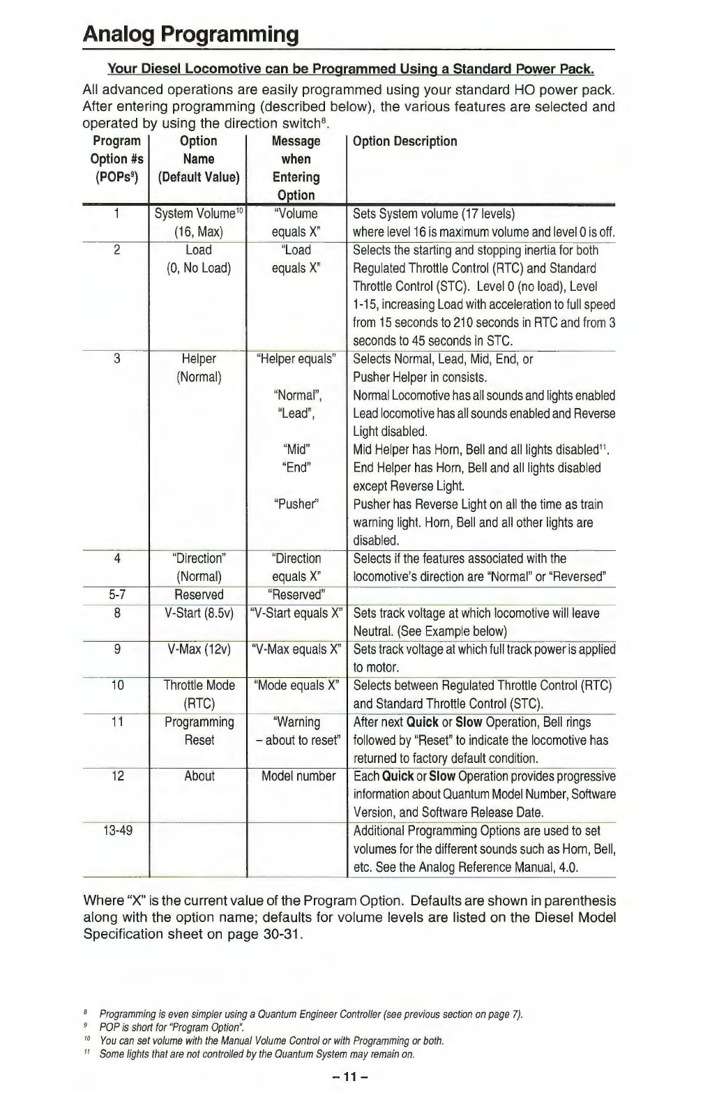
Train Load
You can set your diesel locomotive to have any of
16
different Load levels, which
represent added inertia from rolling stock (see Analog Programming, Option 2
on
page
11
).
The higher the Load setting, the greater the inertia effect during acceleration and
deceleration. Level O
is
the default, which
is
no
Load.
Sound-of-Power™
During acceleration, Diesel Motor sounds will produce heavy labored sounds (based
on
Load setting) until the locomotive has achieved its final speed where it will then
produce standard sounds appropriate to its throttle setting. Under deceleration, the
Diesel Motor sounds are less labored until
it
achieves its final speed where it will again
produce standard Diesel Motor sounds appropriate to its throttle setting.
Helpers
Prototype Helpers are locomotives that are used to provide extra power and/or braking
for a heavily loaded train. The Quantum System allows you
to
easily program how
each locomotive will behave by selecting between a Lead locomotive, Mid Helper,
End Helper, or Pusher. Each type of Helper locomotive has different lights and sounds
enabled or disabled, as described
in
the table under Option
3,
in
Analog Programming,
page
11.
Normal and Reversed Direction
Quantum also allows you to reverse the directional sense of your locomotive. This
is
normally not
an
issue with
DC
two-rail trains since all locomotives will go
in
the same
direction whether they are facing forwards or backwards. However, certain features
like Directional Lighting or diesel Low Idle do depend
on
the directional sense. When
making
up
a train with different Helper types, it
is
recommended that you also change
the directional sense of any Helper that
is
intended to
be
operated backwards within
the consist. See "Option 4 Direction
",
Analog Programming, page
11
.
Additional Analog Operation Features Available with the Quantum Engineer™
Controller
Your Quantum diesel locomotive
is
equipped wi
th
QSl's QARC™ (Quantum Analog
Remote Control) Technology. QARC Technology uses special remote control signals
to operate various Quantum System features without the need for complicated and
expensive digital systems. With QARC technology, you can operate features that are
otherwise available only
in
Digital Command Control (DCC), plus some new features
that are not yet available
in
DCC. QARC will allow you to:
1)
turn
on
or off individual
lights, 2) shut down and start
up
locomotives,
3)
make
up
consists easily,
4)
simplify
Analog programming,
5)
set System Volume or Mute while train
is
operating,
6)
trigger
Coupler Crash sounds,
7)
operate prototype-like Air Brakes,
8)
turn
on
Dynamic Brakes,
9)
activate Status or Speed Reports and operate many other features. The QARC
System makes Analog operation more fun and more prototypical than DCC by
7
Standard
US
prototype
railroad
signaling
is
two
hoots
before
starting
in
forward
and
three
hoots
before
starting
in
reverse.
Other
countries
have
different
signaling.
Check
your
Diesel
Model
Specification
sheet
for
horn
sequences
used
on
your
model.
www.walthers.com -
8-

eliminating the need to configure function keys. Every button
on
the QARC controller
does exactly what
it
is
labeled to do. The only major difference between QARC and
DCC
is
that, with QARC, you are not able
to
independently operate multiple trains
on
the same powered track section at different speeds at the same time.
The QARC controller, called Quantum Engineer™(Walthers Part No. 920-5990), can
be
added to your existing Analog
DC
power pack
in
less than five minutes. Wiring
is
simple: two
red
wires go to the variable
DC
output from the power pack and two
black wires go to the track (FIGURE 1). Place Quantum Engineer beside your power
pack or mount
it
directly
on
most popular power packs as shown
in
FIGURE 2. All
features
on
the power pack remain the same including throttle and reverse switch
control. See our website at http://www.walthers.com
FIGURE 1
WIRING QU
AN
TU
M ENGINEer
IS
SI
MP
LE
. -
-
-
-
-
-
-
-
-
BLACK
-RED -
_
II'
-
-
-
-
-
DC POWER PACK
FIGURE 2
QUANTUM ENGINEER SHOWN ATTACHED
TO STANDARD
DC
POWER PACK
-9-
-
-
-
-
-
QUANT
UM
ENGINEER ADD-ON
CONTROLL
ER
/ STANDARD
DC
POWER PACK

Programming and Sound Control with Quantum Engineer: Figure 3 shows the Star
Pad
key
section of the Quantum Engineer, which controls both sound and programming.
During normal operation, the
Volume•
and Volume T keys control the system volume
and the Mute key toggles the sound between normal and a low volume level.
In
addition,
the STC and RTC keys allow you to easily select between Standard Throttle Control
and Regulated Throttle Control.
Or you can enter Programming Mode by pressing and holding the Prgm key while you
turn
on
the power. The Red power light will blink and your locomotive directional lights
will blink to indicate you have entered programming. Press the Next key
to
advance
from one Programming Option to the next. The locomotive will speak out which Option
you have selected. The Prev key allows you
to
move backwards through Program
Options. Once
you
have selected
an
Option, use the
Volume•
or
Volume T keys to
program that option.
For instance,
if
you wanted to change
the Whistle volume independently or
other sounds, enter programming with
the Prgm key, and press and hold the
Next key until you hear the locomotive
count
up
to thirteen "13" and responds
with
the
verbal
message
"Whistle
Volume". Press the Volume
.._
key to
increase the Whistle volume or press the
Volume T to
decrease
the
Whistle
volume.
As
you press the volume
up
or
down keys, you will hear the Whistle
hoot at each new volume setting. You
can now move to
other
options
by
pressing the Next
or
Prev key. For instance, if you pressed the Next Key, you would
advance
to
the next option, "14" where the locomotive would announce "Bell Volume".
You
can now use the Volume
.._
or Volume T to change the Bell volume and hear the
Bell sound at each new volume setting.
To
leave programming, simply shut off the track
power. See the table
on
page
11
for additional listings of Programming Options.
www.walthers.com
-10-

Analog Programming
Your Diesel Locomotive can be Programmed Using a Standard Power Pack.
All advanced operations are easily programmed using your standard HO power pack.
After entering programming (described below), the various features are selected and
operated by using the direction switch8•
Program
Option
Message
Option
Description
Option
#s
Name
when
(POPs
9)
(Default
Value)
Entering
Option
1
System
Volume
10
"
Volume
Sets
System
volume
(17
levels)
(16
,
Max)
equals
X"
where
leve
l
16
is
maximum
volume
and
level
O
is
off.
2
Load
"
Load
Selects
the
starting
and
stopping
inertia
for
bo
th
(0,
No
Load)
equals
X"
Regulated
Throttle
Control
(RTC)
and
Standard
Throttle
Control
(STC).
Level
O
(no
load)
,
Leve
l
1-15
,
increasing
Load
wi
th
acceleration
to
full
speed
from
15
seconds
to
21
O
seconds
in
RTC
and
from
3
seconds
to
45
seconds
in
STC.
3
Helper
"Helper
equals
"
Selects
Normal
,
Lead
,
Mid
,
End,
or
(Normal)
Pusher
Helper
in
consists.
"
Normal
",
Normal
Locomotive
has
all
sounds
and
lights
enabled
"Lead",
Lead
locomotive
has
all
sounds
enabled
and
Reverse
Light
disabled.
"Mid"
Mid
Helper
has
Horn
,
Bell
and
all
lights
disabled
11•
"
End"
End
Helper
has
Horn,
Bell
and
all
lights
disabled
except
Reverse
Light.
"Pusher"
Pusher
has
Reverse
Light
on
all
the
time
as
train
warning light.
Horn,
Bell
and
all
other
lights
are
disabled
.
4 "
Direction"
"Direction
Selects
if
the
features
associated
with
the
(Normal)
equals
X"
locomotive's
direction
are
"Normal"
or
"Reversed"
5-7
Reserved
"
Reserved"
8
V-Start
(8.5v)
"V-Start
equals
X"
Sets
track
voltage
at
which
locomotive
will
leave
Neutral.
(See
Example
below)
9
V-Max
(12v)
"V-Max
equals
X"
Sets
track
voltage
at
which
full
track
power
is
applied
to
motor.
10
Throttle
Mode
"Mode
equals
X"
Selects
between
Regulated
Throttle
Control
(RTC)
(RTC)
and
Standard
Throttle
Control
(STC).
11
Programming
"Warning
After
next
Quick
or
Slow
Operation,
Bell
rings
Reset
-
about
to
reset
"
followed
by
"Reset"
to
indicate
the
locomotive
has
returned
to
factory
default
condition.
12
About
Model
number
Each
Quick
or
Slow
Operation
provides
progressive
information
about
Quantum
Model
Number,
Software
Version,
and
Software
Release
Date.
13-49
Additional
Programming
Options
are
used
to
set
volumes
for
the
different
sounds
such
as
Horn
,
Bell,
etc.
See
the
Analog
Reference
Manual,
4.0.
Where
"X"
is
the current value of the Program Option. Defaults are shown
in
parenthesis
along with the option name; defaults for volume levels are listed
on
the Diesel Model
Specification sheet
on
page 30-31.
8
Programming
is
even
simpler
using
a
Quantum
Engineer
Controller
(see
previous
section
on
page
7).
9
POP
is
short
for
"
Program
Option
".
10
You
can
set
volume
with
the
Manual
Volume
Control
or
with
Programming
or
both.
"
Some
fights
that
are
not
controlled
by
the
Quantum
System
may
remain
on.
-11-

Entering Programming
Use this simple sequence to enter Programming using the direction switch.
1. Apply power and turn
up
the throttle to hear the sound system come on.
2.
Wi
th
in
five seconds of powering
up,
turn
on
the Bell12 with a Quick flip-and-back
operation.
3. Within three seconds
of
the Bell turning on, turn off the bell with a second Quick
flip-and back operation.
4.
Within three seconds,
tu
rn
the Bell back
on
again with a third Quick flip-and-back
operation.
If you delay too long after power has been first applied, the opportunity to enter
Programming w
ill
time out and you will need to start again by shutting off and reapplying
track power.
Once you perform the three bell operations after applying power, the Bell will shut off
automatically and you
wi
ll hear "Enter Programming" and the Headlight and Reverse
Light will flash alternately off and on.
Scrolling through the Program Options
• After entering Programming, you will hear
an
announcement of the first Program
Option, "Option 1 - System Volume".
• To access other Program Options, simply flip the direction switch
to
the opposite
position and leave
it
there. Listen as each option number
is
announced
in
order.
• When you hear the Option Number you want, flip the direction switch back and
leave it there. After you stop at
an
option you will hear the option number and
name announced. When you are scrolling through and stopping at Program
Options,you are not making any changes.To make changes
you
must actually
enter the Program Option.
Note:
If
you accidentally go
to
a higher option
number
other than the one you wanted, simply
turn the
power
off
, re-enter Programming
and
start again13• Once you reach the last
Program Option, it will continue
to
announce the last option
number
.
Entering a Program Option and Making Changes
After the verbal announcement of a Program Option, you can enter that option by
performing a Slow
or
Quick flip-and-back operation of the direction switch14. Upon
entering a Program Option, you will hear the current setting for that option. For unused
Program Options, you will hear "Reserved". For any volume option, you will hear
"Volume equals
X"
(where "X" is its current volume level setting). After a moment, you
will hear the sound playing at its current volume15•
Note: It is easy
to
distinguish between doing a Quick
and
Slow operation. When you flip the
direction switch
to
do a Slow operation, wait until
you
hear
a low level "hiss"
sound
from
the locomotive
and
then immediately flip the direction switch back.
To
do a Quick
operation, make sure you flip the direction switch back before you
hear
the "hiss"sound.
Note: Entering a Program Option does
not
change the settings for that option; it only provides
information aboutits current value.
After
entering the Program Option, additionalSlow
or
Quickflip-and-back operations willprogram
new
settingsas described
in
the above table.
Foral/ leveladjustments, a Quick operation will decrease one level, while a Slowoperation
will increase one level.
Note: Since "System Volume"is the first Program Option, you can use Quick
or
Slowoperations
immediately after entering Programming to change the System Volume.
Moving
on
to Other Program Options or Leaving Programming
• Flip the direction switch at anytime to the opposite position, and leave
it
there.
The Quantum System will first return to and announce the current Program Option
and then automatically advance
on
to higher options.
• Exit Programming anytime you want by turning the power off and then back
on
again.
12
If
your
locomotive
does
not
have
a
prototype
Bell
enabled,
a
single
feedback
ding
indicates
you
have
entered
the
Bell
State
and
a
double
ding
indicates
you
have
left
the
Bell
State.
13
If
you
have
a
Quantum
Engineer,
you
can
move
both
back
and
forth
through
Program
Options.
14
If
you
have
a
Quantum
Engineer
,
Quick
and
Slow
operations
are
done
with
specific
program
buttons.
15
Setting
any
volume
in
Analog
will
also
apply
to
DCC
and
vice-versa.
www.walthers.com
-12-

Example 1: Setting Throttle Mode {Program Option #10)
This will determine whether your locomotive uses Regulated Throttle Control (RTC) or
Standard Throttle Control (STC).
• Enter Programming after powering
up
your locomotive
by
turning the Bell
on,
then
off and then on
as
described
on
page
12.
• After the "Enter Programming" followed by "Option One -System Volume"
announcement of the first Program Option, flip the direction switch and leave it
there. You will hearthe announcement "Option 1,2,3 ... etc." Stop when you hear
"one-zero"
by
moving the direction switch back. You will hear 'Throttle Mode".
• Use a Slow
or
Quick operation of the direction switch to enter this option.
If
the
throttle mode
is
at its default value (RTC
),
you will hear "Mode equals Regulated
";
otherwise, you will hear "Mode equals Standard".
• Use a Slow
or
Quick operation of the direction switch to change the Throttle
Mode. Repeated Slow
or
Quick operations will cause the throttle modeto alternate
between its two possible values "Regulated" or "Standard".
• Once you have selected the Throttle Mode you wish to use, turn the throttle
off.
When you power
up
again, your locomotive will be using the Throttle Mode that
you have just selected.
Example
2:
Setting V-Start {Program Option #8)
This option will determine the voltage (and throttle position) at which the locomotive
will leave Neutral and start moving.
• Enter Programming after powering
up
your locomotive
by
turning the Bell
on
,then
off and then on -as described above.
• After the "Enter Programming" announcement followed
by
"Option One -System
Volume" announcement for the first Program Option, flip the direction switch and
leave it there. You will hear the announcement "Option
1,
2, 3 .
..
etc.
".
Stop when
you hear the number
"8'
' by moving the direction switch back. You will hear "
V-
Start".
• Use a Slow
or
Quick operation of the direction switch
to
enter this option. You will
hear "V-Start equals X" where "X"
is
the track voltage value currentlyset for leaving
Neutral.
• Use a Slow
or
Quick operation of the direction switch to activate this option. Hear
the message "Set throttle to V-Start." After three seconds, the voltage will
be
announced.
If
you move the throttle, the new track voltage value
is
announced a
few seconds later.
• Once throttle
is
set, use a Slow
or
Quick operation of the direction switch to start
the V-Start voltage setting procedure. The locomotive will move at a slow speed
and the Bell will ring continually for about 25 seconds, indicating the correct value
is being calculated.
If
you chose a very low voltage setting, be patient.
If
the
locomotive does not move during this procedure, return to the beginning of this
option or start over16 and then chose a slightly higher throttle setting.
• At the end of the process, the locomotive will stop moving and the Horn will hoot,
signifying the end of the operation, and you will hear the message "V-Start =
X"
where "X"
is
the new setting.
• To leave Programming, turn the throttle
off,
and then power
up
for normal locomotive
operation.
• Or continue to V-Max
by
moving the direction switch and waiting for the next
Programming Option
to
be
announced.
16
See
section
on
page
12:
Moving
on
to
Other
Program
Options
or
Leaving
Programming.
-13-

Example
3:
Setting V-Max (Program Option #9)
V-Max
is
set
in
the same manner
as
V-Start except after entering this Program Option,
you will hear "Set throttle to V-Max" which
is
the throttle position where you want the
full track voltage to be applied to the motor (usually about 80% of full throttle)17. Then
do a Quick
or
Slow operation to start the V-Max setting procedure. Like V-Start, the
bell will ring continually until the voltage
is
set followed by a Horn hoot to indicate the
procedure
is
finished. Setting V-Max
is
much quicker than V-Start.
Note: During the V-
Max
setting, the locomotive will
not
move as it does
under
V-Start.
For more information, download the Quantum Analog Reference Manual (Version 4) from
http://www.walthers.com then select the technical help link on the menu bar.
17
V-Max
should
not
be
set
too
low
when
using
RTC.
For
most
MRC™
power
packs
,
the
best
choice
for
V-
Max
is
about
1.5
volts
below
the
highest
throttle
setting
as
determined
by
the
Quantum
built-in
Voltmeter
.
www.walthers.com
-14-

DCC Operation
These steps will allow you to start operating your Quantum equipped diesel locomotive
immediately using any DCC system that
is
compatible with the applicable NMRA DCC
specifications.
1.
Select locomotive number
3.
2. Set your
DCC
controller
to
128 (preferable) or 28 (acceptable) speed step range.
3.
Start your locomotive immediately
by
pressing the
F6
DCC function key18
to
hear
the locomotive Start
Up
sounds. The Directional Lighting System (Front Headlight,
Reverse Light (Rear Headlight), Mars Light and Ditch Lights19)
will
be
on.
The
Cab Lights
and
Number Board Lights
will
be
on.
The Cab Lights will shut off
automatically after
ten
seconds.
4.
Increase the throttle to leave Neutral and start the locomotive moving. The
locomotive
will
start out slowly due to special Quantum Inertial Control™ that
resists rapid increases or decreases
in
speed. When
you
reduce the throttle
to
zero,
you
will hear a Short Air Let-off when the locomotive stops moving indicating
that
it
has entered Neutral; a
Long
Air Let-off will occur about one second later,
followed by Air Pumps
and
other background sounds20.
The direction of your locomotive will change when you press the direction key
on
your
DCC throttle.
• Locomotive Inertia Effects
• Your new locomotive
is
pre-programmed
at
the factory
to
use Regulated Throttle
Control (RTC)
in
DCC
operation.
RTC
makes your model operate
as
though
it
has
the mass
and
inertia of a prototype locomotive.
As
a result, your locomotive
will
resist starting
up
too quickly
if
at
rest
and
will resist changes
in
speed once moving.
It takes a little practice
to
learn
to
move the throttle slowly and wait until the
locomotive responds.
If
you
preferthat your locomotive respond almost immediately
to the throttle,
it
may
be
reprogrammed
to
use
Standard Throttle Control (STC)
in
CV56.4.
Function Keys
The following table lists features that have been pre-assigned to your DCC function
keys.Operation of these keys can
be
different
in
the Neutral state (locomotive stopped)
and the Motive states (locomotive moving
in
Forward or Reverse). After you have
selected your locomotive, simply press any of the function keys listed below to produce
the described effects.
Function
Key*
Forward
and
Reverse
Neutral
F0
or
FL
Directional
Head
,
Reverse,
Mars
Directional
Head,
Reverse,
Mars
or
Headlight
and
Ditch
Lights
on/off
and
Ditch
Lights
on
/
off
F1
Bell
on/off
(if
assigned
21
)
Bell
on
/
off
(if
assigned)
F2
Horn
or
horn
with
Doppler
Effect
Horn
(see
page
17)
F3
Coupler
Crash
/
Coupler
Fire
Coupler
Arm
or
Coupler
Fire
F4
Cooling
Fans
on/off
Cooling
Fans
on/off
F5
Dynamic
Brake
function
on/off
Dynamic
Brake
function
on
/
off
(in
"D
isconnect
"
only)
F6
Initiate
Doppler
Effect
Start
Up
F7
Squealing
Brake/Flanges
Brake
Set
-
Long
Air
Let-off
and
Air
Brakes
F8
Audio
Mute
on/off
Audio
Mute
on
/
off
F9
Very
Heavy
Load
on/off
Disconnect/Standby
/
Shut
Down
F10
Locomotive's
Speed
Report
Status
Report
F11
Number
Board
or
Marker
Lights
on/off
Number
Board
or
Marker
Lights
on/off
F12
Cab
Lights
on/off
Cab
Lights
on/off
* Quantum supports the new NMRA 0-12 function key standard; the old 0-8 standard is
not
supported.
18
It
d
oes
not
need
to
be
F6
;
any
function
or
speed
command
will
activate
the
locomotive.
It
is
on
ly
when
a
locomotive
is
in
Shut
Down
that
an
F6
command
is
necessary.
19
The
lighting
features
available
depend
on
the
locomotive
model.
20
Neutral
sounds
also
include
Cooling
F
ans
with
Vents
opening
and
closing
that
turn
on
and
off
randomly.
21
If
the
prototype
did
not
have
a
bell
,
no
bell
feature
is
assigned
to
Ft
and
no
other
feature
is
assigned
in
its
place
.
-15-

If you have a DCC command station that supports only the older Oto 8 function key
standard, you will have no way to initiate Shut Down
in
Neutral with these pre-assigned
feature to function key mappings. There
is
an
interim solution to this problem; Swap
the features assigned to the
F7
and
F9
outputs
in
Neutral by doing the following:
1.
Set CV49 to 9,set CV50 to
1,
and set CV53to
145.
Now
F7
in
Neutral controls Shut
Down.
2.
Set CV49
to
11
, set CV50 to
1,
and set CV53 to
9.
Now
F9
in
Neutral controls
Long Air Let-off.
Automatic Features
Automatic Quantum Features depend on the directional state of the locomotive.
Automatic Control can be enabled or disabled by their indicated function keys. The
state of each Automatic feature
in
each direction
is
shown
in
the table below.
Feature
Function
Key
Forward
Neutral
Reverse
Neutral
from
Forward
from
Reverse
Headlight
F0
or
FL
Bright
Dim
22
Dim
Dim
Reverse
Light
F0
or
FL
Dim
23
Dim
Br
igh
t
Dim
Mars
Light
F0
or
FL
Strobing
Steady
On
St
eady
On
Steady
On
Ditch
Lights
F0
or
FL
On
Off Off Off
Number
F11
On
On On On
Board
Lights
Marker
Lights
F11
On On On On
Cab
Lights
F12
Off
after
On
after
Off
afte
r
On
after
15
seconds
10
seconds
15
seconds
10
seconds
Vents
&
F4
On
after
Off
after
On
after
Off
afte
r
Cooling
Fans
20
seconds
10
seconds
20
seconds
10
seconds
When
an
indicated function key enables
an
"automatic" light feature, the associated
lights operate according to the states shown
in
the table. For instance, enabling the
Automatic Ditch Lights
in
Neutral will not cause the Ditch Lights to turn
on
since their
automatic behavior would have them off
in
that directional state; however,
it
you then
entered Forward, the Ditch Lights would turn on. When an indicated function key
disables
an
"automatic" feature, all lights will
be
off. For instance, disabling "Automatic
Ditch Lights" will immediately shut off any operating Ditch Lights and they will not turn
on
again until the automatic feature
is
enabled.
Note: Use CV55
to
change the behavior
of
lights from what
is
described
in
the above table.
Note: Not all features may be available
in
your locomotive model.
In
particular, Number Board
Lights and Marker Lights have not been offered for the same model.
F11
is
assigned
to
the feature that
is
available.
Note: Lights and other features can be assigned
to
function keys and configured
to
different
kinds
of
operation andinitial conditions
in
CV
53 (Output Feature Assignment) andCV55
(OSI Feature Configuration). See the Quantum DCC Reference Manual, version
4.
Coupler and Coupler Crash Sounds (F3)
There are two ways to use the
F3
key.
•
In
Forward or Reverse,
as
your locomotive
is
moving to couple
up
to a string of
cars, press the
F3
key to trigger the crashing sound of a locomotive coupling. Use
the
F3
key again
as
the locomotive
is
moving out to produce the same sound
as
the slack
is
taken
up
in
the cars.
• Use the
F3
key
in
Neutral to produce uncoupling sounds
as
you
disconnect cars
over uncoupler magnets. Press the
F3
key once to produce the sound of the lift
bar and coupling
pin
being raised. This first press also arms the uncoupling sound
effect. Press the
F3
key again while moving or
in
Neutral to produce
the
sound of
the coupler knuckle opening and the air-lines parting.
Note:
If
you have armed the Coupler
in
Neutral and are now
in
Forward
or
Reverse, pressing
the F3 Key will produce the coupleropening sound. Thereafter, as you continue
in
Forward
or
Reverse, the F3 Key will produce Coupler Crash Sounds.
22
If
your
locomotive
has
a
Mars
Light
,
the
Headlight
will
be
off
(instead
of
"
Dim
")
in
all
states
except
Forward
where
it
will
be
Bright.
23
Quantum
1
Reverse
Lights
cannot
be
dimmed
;
they
only
have
bright
and
off
settings.
www.walthers.com
-16-

Sound-of-Power™
If CV3, or CV23 and CV4, or CV24 has been set to non-zero positive values, your
diesel
locomotive
will
produce
additional labored Diesel
Motor
sounds
under
acceleration and lighter Diesel Motor sounds under deceleration. The level of labored
sounds
is
proportional to the values for these four CVs, and how much the throttle
is
increased or decreased.
Diesel Motor RPM: Quantum has all eight diesel-motor throttle "notches" found
on
prototype locomotives. As you increase the throttle, you will hear the RPM's increase
for every increase
in
ten speed steps (at 128 speed step setting). Idle
is
considered
Notch 1 and occurs for speed step
0.
Notch 2 ranges from 1 to 10, Notch 3 from
11
to
20
, Notch 4 from
21
to 30,etc. If your controller has
an
option to increment or decrement
your throttle set setting by ten speed steps,
it
is
very easy and predicable to set your
notch value.
Horn and Bell Buttons (F2, F1)
Some DCC controllers have separate horn and bell buttons along with function keys
assigned to horn and bell operation. The bell
is
usually assigned to
F1
and the horn
is
usually assigned to
F2.
The
F2
key behaves differently than using the horn button.
• Pressing the
F2
key and releasing
it
will
cause the horn command to come
on
and
stay
on,
until
you
press
F2
again.
• Pressing the horn button will send the horn command only
as
long
as
you
hold the
button down.
Pressing the
F1
key and releasing
it
will cause the Bell to come
on
and stay
on
, until
you press
F1
again. There
is
no difference
in
operation between the bell button and its
corresponding function key.
Note:
If
your locomotive
is
equipped with Ditch Lights, they will automatically strobe from one
light
to
the other when the Horn is being blown and will continue for five seconds after the
horn signal has stoppec
J24
.
Note: Since the prototype horn uses compressedair, you will hearthe
Air
Pump sounds turn on
after the Horn is operated.
Doppler Operation (F6)
With DCC, you can trigger the Doppler Effect by quickly interrupting the horn signal
in
the same way as described under Analog Operation. Or, you can use the function key
(F6) assigned to the Doppler Effect.
• Start the Horn and/or Bell by pressing and releasing their function keys.
• Press
F6
to hear the Doppler shift. A few seconds after the horn button
is
turned
off with the
F2
key
the diesel locomotive sounds return to normal.
Note:
If
you
do
not turn on either Horn
or
Bell, the Doppler shift will still occur but will be less
dramatic.
Note:
If
the Bell was
on,
it will shut
off
prior
to
sounds returning
to
normal.
Squealing Brake and Flange Sounds (F7)
Quantum provides automatic brake squeal as a locomotive slows to a stop. The operator
can also control squealing sounds for continuous and variable brake sounds for
protracted stops or to simulate the sounds of squealing wheel flanges
on
curved track.
• To enable Automatic Squealing Brakes operate the locomotive over 40 smph
(64
skph). Squealing brakes sounds will then sound automatically when the speed
is
reduced to less than 20 smph
(32
skph).
• Pressing the
F7
key when the locomotive
is
moving
at
any speed will manually
activate Squealing Brake sounds, and repeated pressings while the Squealing
Brake sounds are occurring will continue
the
sounds uninterrupted.
Note:
If
you slow the locomotive too quickly, the brake sounds will terminate abruptly when the
locomotive stops and enters Neutral.
Note:
If
you loweryour throttle
to
speedstep
Oona
moving locomotive, the F7 key will applyAir
Brakes
to
slow the locomotive. See next section.
24
The
hold
time
for
strobing
Ditch
Lights
after
the
horn
button
is
released
can
be
set
in
CVSS.84.5.
-17-

Air Brakes (F7)
If you have selected any non-zero deceleration inertia or momentum value
in
CV4 and/
or CV24, the F7 key can be used to apply Air Brakes to stop the locomotive more
quickly than it would normally stop from the inertia settings25 . To use Air Brakes:
• Turn the throttle down to speed step O
on
a moving locomotive; this enables the
F7
key to act as a brake.
• Press the
F7
key. Heara brief brake squeal sound and air being released from the
brake lines continually. The longer the air is released the greater the braking
action.
Note:
Fl
will apply brakes when set
to
1 and stop the
air
release when set
to
0.
Depending
on
the initial setting for
Fl
when you turn your throttle down
to
speed step zero, you may
need
to
press the
Fl
key twice
to
first apply brakes.
• Press the
F7
key again to stop the air release. The train will continue to slow at the
last braking value.
•
If
you want to apply more braking, press the
F7
key again to release more air.
When you reach the desired amount of braking, press
F7
again to stop the air
release.
Note:
If
you continue
to
release air, all the pressure will eventuallybe released andbrakes are
on full; you will hear no further
air
release sounds.
• Turn
up
the throttle to any value above Oto release the brakes; this action resets
the locomotive's deceleration to a value determined bythe sum of CV4 and CV24.
•
If
the locomotive
is
in
Neutral when the
F7
key
is
pressed, the Long Air Let-off
sound simulates setting the brakes. However, no braking effect
is
activated26.
Note:
If
the throttle is set
to
any
speedstep except
0,
Air
Brakes are notenabled; instead the
Fl
key will now manually activate Squealing Brake/Flange sounds but will not affect the
locomotive's deceleration.
Note:
If
the direction state
is
changed while moving,
Fl
is enabled
to
act
as a brake without the
need
to
reduce the throttle
to
speed step
0.
After stopping and changing direction, the
loco will accelerate back
to
its original speed.
Three Stages of Diesel Locomotive Shut Down:
1.
Disconnect,
2.
Standby,
3.
Total Shut Down (F9)
Locomotive Shut Down has three distinct stages that you can control. Each stage is
entered by double pressing the F9 key
27
.
Stage
One:
Disconnect
• Double press the
F9
key
in
Neutral to enter Disconnect. You will hear a Long Air
Let-off. The motor drive will be disabled. The DCC throttle can
be
moved
up
and
down without the diesel locomotive moving. As the throttle
is
moved
up
or down,
you will hear the Diesel Motor rev
up
and down
in
proportion
to
the throttle setting.
All Function Keys are active
in
Disconnect.
• To leave Disconnect, either double press the
F6
Start
Up
key, as described
in
the
Start Up section or double press the
F9
key again to reach Standby, the next
stage of Shut Down.
Note:
In
Disconnect, you can also turn on the Dynamic Brakes (see description
of
Dynamic
Brakes on page
19)
to
create Sound-of-Power as the throttle
is
moved up and down.
Engineers on prototype diesels use dynamic brakes
to
load the motor-generator to test
its output efficiency while the locomotive remains stationary.
Stage Two: Standby
• Double press the
F9
key while
in
Disconnect to enter Standby. You will hear a
Long Air Let-off followed by a special "Low Idle" sound. The Directional Lighting
and optional Ditch Lights or Mars Light will shut down.
25
CV4
and
CV24
determine
the
deceleration
rate.
Applying
the
brakes
increases
the
deceleration
rate
temporarily.
28
If
the
brakes
are
set
in
Neutral
,
turning
up
the
throttle
automatically
releases
the
brakes
.
27
Double
pressing
is
defined
as
two
F9
commands
sent
within
two
seconds.
Note
that
the
F9
key
may
have
to
be
pressed
three
times
,
due
to
the
DCC
command
station
and
locomotive
having
different
initial
states
for
F9
.
Double
pressing
ensures
that
Shut
Down
stages
are
not
entered
or
exited
accidentally.
www.walthers.com
-18-

Note:
The
motorwill remain disconnected, while the
Air
Pumps, automatic Cooling
Fan
operation,
NumberBoard Lights andCab Lights will continue
to
operate.
In
Standby, the locomotive
will not respond
to
throttle
or
function
keys2
8.
The
three exceptions are the F6 Start
Up
Key, the
FB
Mute Key (described on page 20) and the F10 Status Key (described on
page 21).
• To leave Standby, either double press the
F6
Start
Up
Key,
as described
in
the
Start
Up
section, or double press the
F9
key again to reach the final stage
of
Shut
Down: Total Shut Down.
Note: Standby
is
ideal for leaving yourlocomotive running on a siding. Besides hearing the Low
Idle diesel motor sounds, the locomotive will not respond
to
accidentally changing the
throttle setting
or
pressing the function keys.
Stage Three: Total Shut Down
Total Shut Down allows the operator to take the locomotive "off line" (turn off sounds,
lights, ignore throttle settings and function commands) independent of the operating
session: the locomotive will still be "off line" when power
is
reapplied for the next
operating session, regardless of whether the next session
is
Analog (conventional
DC) or DCC.
• Double press the
F9
in
Standby to enterTotal Shut Down.
You
will hear a Long Air
Let-off. The Air Pumps will turn off, followed
by
the Number Boards (if so equipped)
and the sounds of the Cooling Fans shutting
off,
the louvers closing, the Diesel
Motor shutting down and finally, the Cab Lights (if
so
equipped) turning off. A few
seconds later
you
will hear the engineer's door open and then shut.
Note: In Total Shut Down, the locomotive will not respond
to
throttle
or
function keys.
The
two
exceptions are the F6 Start
Up
Key (described below) andthe F10 Status Key (described
below).
• To leave Total Shut Down, double press the
F6
key.
Note:
If
power
is
turned
off
at
any
stage
of
Shut Down (Disconnect, Standby
or
Total Shut
Down)
or
during a Shut Down procedure, the locomotive will remember the last Shut
Down stage it was
at
during power down, and the locomotive will power up
in
the same
stage.
If
Start
Up
is
initiated during
any
of
the above Shut Down procedures, Shut Down
is
aborted,
and
locomotive will return
to
normal operation.
Dynamic Brakes (FS)
The prototype diesel locomotive usually has dynamic brakes that cause the train to
slow down by using the traction motors
in
generator (rather than motor) mode. This
method of braking dissipates the energy of a moving train by converting
it
to electrical
power, which
is
then applied to a large air-cooled resistor load
in
the locomotive.
• Pressing the
F5
key
in
Forward or Reverse will set the locomotive's Diesel Motor
sound to idle at the lowest Sound-of-Power setting and turn
on
the powerful
Dynamic Brake Cooling Fans.
• Pressing the
F5
key
in
Neutral
in
"Disconnect" will turn
on
the Dynamic Brake
Cooling Fans while Diesel Motor sounds remain
at
idle.
Dynamic Brakes automatically turn off when entering or leaving Neutral, when
locomotive speed drops below 7 smph
(11
skph)29, or when the throttle
is
turned up.
Dynamic Brakes cannot be turned
on
in
Forward or Reverse unless the locomotive
speed
is
over 8 smph (13 skph).
Note: In contrast
to
Air
Brakes
(Fl)
, Dynamic Brakes do not increase the deceleration rate
specified
by
CV4 and CV24.
Start Up (F6)
If your Quantum equipped diesel locomotive is
in
any stage of Shut Down, you can
return it to normal operation by double pressing30 the
F6
key. Start
Up
will
be
different
for each stage of Shut Down, but all will start up with a Long Air Let-off and will enter
normal operation.
28
Pressing
a
function
key
will
only
produce
a
Short
Air
Let-off.
29
Dynamic
Brakes
on
prototype
locomotives
are
less
effective
and
are
seldom
used
at
low
speeds.
30
Double
pressing
is
defined
as
two
F6
commands
sent
within
two
seconds.
Note
that
the
F6
key
may
have
to
be
pressed
three
times
,
due
to
the
DCC
command
station
and
locomotive
having
different
initial
states
for
F6
.
Double
pressing
ensures
that
Start
Up
is
not
entered
accidentally.
-19-

Start Up from Disconnect:
If
you double press the
F6
key
in
Disconnect, the diesel
locomotive will produce a Long Air Let-off, Dynamic Brakes will shut off and the
locomotive will enter normal operation.
Start Up from Standby: If you double press the
F6
key
in
Standby, the diesel locomotive
will produce a Long Air Let-off, Directional Lighting will turn on, the Diesel Motor sound
will change from the special Low Idle to regular Idle, and the locomotive will enter
normal operation.
Start Up from Total Shut Down:
If
you double press the
F6
key
in
Total Shut Down,
the diesel locomotive will produce a Long Air Let-off, you will hear the engineer's door
opening and closing, and see Cab Lights come
on
(if so equipped), Number Boards
come
on
(if so equipped), and Directional Lighting turn
on
(if previously on). These
actions are followed by the sounds of vents opening, the Diesel Motor starting
up,
the
Air Pumps starting
up,
and the locomotive entering normal operation.
Note: During the Start
Up
procedure, none
of
the DCC function keys are active. However,
if
the
throttle
is
turned up from zero during
any
of
the above Start
Up
procedures, the Start
Up
procedure will abort and the locomotive will enter normal operation.
Mute (F8)
The Quantum System allows you to reduce the System Volume
to
a lower level or
increase
it
back to its original setting using the
F8
function key. This capability
is
useful
when you need to reduce the sound
to
engage
in
a conversation or to answer the
phone. If you have many trains operating at once, you can reduce the volume
on
all
those that are running
in
the background of the layout and increase the volume of the
closest locomotive. The Mute feature changes the sound gradually over a second or
two, which allows the sound to increase or decrease realis
ti
cal
ly
as the locomotive
approaches or recedes from the observer.
• Press the
F8
key
in
Neutral
or
Forward/Reverse
to
gradually decrease or increase
the locomotive's volume.
Note: Mute state
is
notmaintained
if
power
is
turned
of
f and then turned back on; the locomotive
will return
to
full system volume setting.
Note: Mute Volume can be programmed
in
CV51.1.
Heavy Load (F9)
Heavy Load
is
applied while the train
is
moving; it
ma
intains the train at a steady
speed while allowing you to have control over the sound effects of a working locomotive.
Under Heavy Load, changing the throttle will have little affect
on
the locomotive's speed.
Instead you use the throttle to control a diesel's notch and laboring Sound-of-Power
effects. When you approach a grade under Heavy Load, increase the throttle and hear
the locomotive rev
up
with heavy laboring sounds. When the locomotive goes down a
grade, reduce the throttle to hear the locomotive's rev drop with light laboring sounds.
You control which notch or the change of revs and labored sounds
by
how much the
throttle
is
increased or decreased from its initial position (where Heavy Load was turned
on).• Press
F9
and
hear one short hoot when Heavy
Load
is
turned
on
• Press
F9
and hear two short hoots when Heavy
Load
is
turned
off.
You can apply Heavy Load as soon as you start moving or wait until you are
up
to
speed.
Note: Return the throttle
to
its initial setting (where Heavy Load was turned on)
to
avoid
acceleration
or
deceleration when Heavy Load is turned off.
Note: Heavy Loadcan only be turned on
or
off
in
Forward
or
Reverse.
If
turned
on,
it will remain
on
in
Neutral. Ifyou want
it
off when you start out from Neutral, immediately
do
so when
the throttle
is
turned
up.
Note: Heavy Load
is
automatically turned
off
when track power
is
turned off.
Note: Heavy Load represents a train that would take over ten minutes
to
accelerate
to
full
speed
or
to
bring
to
a complete stop. It
is
independent
of
any inertia (or momentum)
values set
in
CV3,
4,
23,
or
24.
Note: Under RTC and Heavy Load, grades, voltage changes, tight curves
or
other real loading
effects, will have little effect on the speed
of
the train. Under STC and Heavy Load,
grades, loading, etc. will affect the train speed as it moves around the layout.
www.walthers.com
-20-

Status (F10)
The Quantum System provides verbal information about the locomotive's current
operating state when the locomotive
is
in
Neutral or the locomotive's current speed
in
scale miles per hour when the locomotive
is
moving.
• Press the
F1
Okey
in
Neutral;the locomotive
will
verbally report its currently enabled
long or short DCC address followed by its consist
ID
(if it has one), followed by its
Shut Down state,
if
any (Disconnect, Standby or Shut Down).
• Press the F10 key
in
Forward or Reverse; the locomotive will verbally report the
locomotive's speed
in
scale miles per hour (smph) or
in
scale kilometers per hour
(skph)
31
•
Note: When Status Report (or Verbal Speedometer Readout)
is
activated, the locomotive's
sounds will reduce
to
one half their current volume settings during the verbal report.
Locomoti
ve
sounds return
to
normal volume when the report has ended.
Note:
In
a consi
st,
all locomotives will s
im
ultaneously report their status when the F10 key is
pressed unless disabl
ed
in
CV22.
Note: Status in Forward and Reverse can be configured
to
also report the Back EMF value and/
or
mot
or
Pulse Width Modulation (P
WM)
value. See CV55, QSI Feature Configuration
in
th
e Quant
um
DCC Refe
re
nce
Ma
n
ua
l, version
4.
Functi
on
Key
Operation in
Ne
utral
Some function keys used in Forward and Reverse will have different effects when
used
in
Neutra
l:
• •The
F7
key produces
Sq
uealing Brake Sounds or applies brakes for a movi
ng
locomotive but produces a Long Air Let-o
ff
in Neutra
l.
• Pressi
ng
F6 results
in
Doppler shift for a moving locom
oti
ve
b
ut
activat
es
Start Up
in Neutral.
• Pressing
F9
turns
on
/off the Heavy Load feature
in
a movi
ng
locomotive but
activates Shut Down
in
Neutral.
Note:
The
Horn, Bell, Doppler Shift, Squ
ea
ling Brake and Neutral sounds are described
in
detail on pages 25-26,
in
the Quantum System Sounds section
of
th
is
manual.
3'
Scafe
speed
report
can
be
programmed
to
announce
in
smph
or
skph
under
DCC
in
CV
56
.0, w
hich
w
ill
apply
to
both
DC
Analog
and
DCC
operation
.
-21-

DCC Programming
Most DCC command stations currently available will program Quantum equipped
locomotives
in
Service Mode32
on
a programming track or Operations (Ops) Mode
on
the main track.
In
Service Mode, your locomotive (if queried) will report back CV values
to your command station.
In
Ops Mode, reports are verbal using the locomotive sound
system.
Changing the System Volume Electronically
in
CV51.0
You can change the volume either manually (as described
in
the Special Operation
and Troubleshooting section) or electronically using OSI
CV51
.0
in
DCC. To change
volume
in
Service or Ops Mode, do the following:
• Set CV49 to
0.
33
• Enter the System Volume
in
CV51
.The System Volume can
be
set
to
any value
between 0 (no sound) and 127 (100%). The default System Volume
is
127.
Note: When you change the System Volume
in
Ops Mode, you will immediately notice the
change
in
volume.
Note: System Volume changes
in
DCC also apply
to
Analog and vice-versa.
Changing the Mute Volume Electronically
in
CV
51.1
To change the Mute Volume
in
Service or Ops Mode, do the following:
• Set
CV
49 to 1.
• Enterthe Mute Volume
in
CV
51
.The Mute Volume
can
be
setto any value between
0 (no sound) and 63 (50%). The default Mute Volume
is
0.
Note: When you change the Mute Volume
in
Ops Mode, and the locomotive is muted, you will
immediately notice the change
in
Volume.
Note:
The
effective Mute Volume level will be the smaller
of
the Mute Volume setting
or
one-
half
the current System Volume.
In
other words, the effective Mute Volume will neverbe
more than one half
of
the System Volume.
Enable/Disable Horn Triggered Doppler Shift (CV51.2)
• Set CV49 to
2.
• Set
CV51
, bit Oto Oto disable Horn Triggered Doppler; set to 1 to enable Horn
Triggered Doppler.
Changing Individual Sound Volumes (CV52.X 34)
To change the volume of individual sounds listed
in
the table below do the following35:
• Set CV49 to the Primary Index for the individual sound from the table below.
• Enter Volume level
in
CV52 as follows:
"0"
= No sound, "1 - 15" sets volume from
the lowest level at "1" to the highest at "15", with volume levels at 2db increments.
Primary
Index
entered
into
CV49
Individual
Sound
0
Horn
8
Bell
10
Diesel
Motor
14
Turbo
16
Air
Pump
19
Vents
and
Cooling
Fans
21
Long
Air
Let-off
22
Short
Air
Let-off
24
Squealing
Brakes/Flanges
28
Dynamic
Brakes
34
Coupler
Sounds
37
Air
Brake
Sounds
See your
Diesel
Model
Specifications
sheet
on
page 30-31 for Individual Sound Volume default settings.
32
If
your
DCC
command
station
will
not
program
in
Service
Mode
,
check
with
the
command
station
manufacturer
;
some
companies
will
give
you
a
free
upgrade
.
Also
,
see
Special
Operation
and
Troubleshooting
on
page
27.
33
In
Ops
Mode,
you
will
hear
the
value
spoken
out
when
changing
the
value
of
a
CV.
34
'X'
refers
to
the
value
in
column
1
of
the
table,
the
Primary
Index
number
that
will
be
entered
into
CV9.
35
Setting
any
Individual
Sound
Volumes
in
DCC
will
also
apply
to
Analog
and
vice-versa.
www.walthers.com -
22-
This manual suits for next models
2
Table of contents
Other Walthers Toy manuals

Walthers
Walthers Cornerstone 933-4079 User manual

Walthers
Walthers Cornerstone Series User manual

Walthers
Walthers Cornerstone Series User manual

Walthers
Walthers CORNERSTONE BRICK KILN 933-4100 User manual

Walthers
Walthers CORNERSTONE WALTON AND SONS LUMBER 933-3235 User manual

Walthers
Walthers Cornerstone Series Product guide

Walthers
Walthers Cornerstone 933-2926 Product guide

Walthers
Walthers Proto 2000 Series User manual

Walthers
Walthers Walthers Mainline RDC-1 User manual

Walthers
Walthers Cornerstone Series User manual