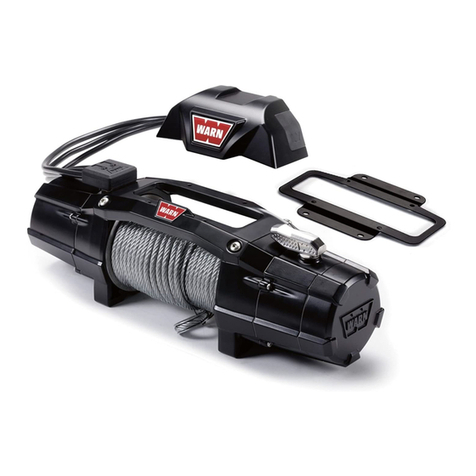
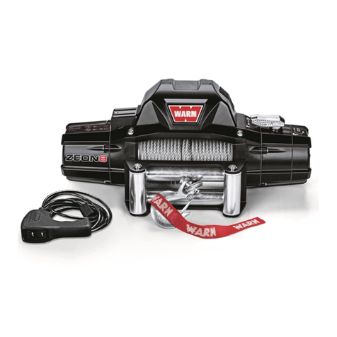
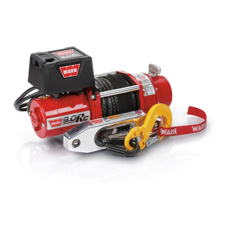
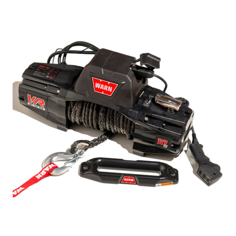
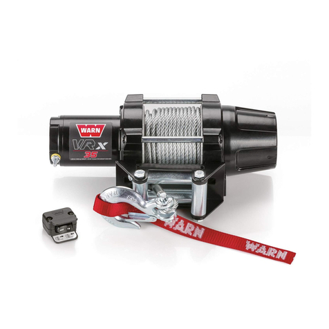
Warn ZEON Specifications

Warn Industries, Inc.
12900 S.E. Capps Road
Clackamas, OR USA 97015-8903
1-503-722-1200 FAX: 1-503-722-3000
www.warn.com
Customer Service / Service Clients: 1-800-543-9276
© 2016 Warn Industries, Inc.
WARN®, the WARN logo are registered trade-
marks of Warn Industries, Inc.
WARN® et le logo WARN sont des marques
déposées de Warn Industries, Inc.
ZEON® Platinum Winch and
Advanced Wireless Remote Control
INSTALLATION AND OPERATOR’S GUIDE
GUIDE D’INSTALLATION ET OPERATEUR
92821A4

English .......................................................................... 1
Français ......................................................................25
Español .......................................................................49
92821A4
92821A4

Every winching situation has the potential for personal injury. In order to minimize that risk,
it is important to read ALL instructions and safety information regarding your product. Please
familiarize yourself with the operation of your winch before using it and be constantly safety
oriented. These instructions provide important safety information and instructions on how to
install and operate your winch.
In this kit you will find the following pieces of literature:
• Winch Installation Guide/ First Time Operation Instructions
• Product Warranty
SAVE THIS MANUAL and other product literature for future reference and review frequently
for continuing safe operation.
Instruct all users of this product to review this manual before operating this product.
Additional Product Literature Available Online
:
• Basic Guide to Winching Techniques
• Provides a basic understanding of the winch and teaches basics of proper winching
techniques. It is a valuable resource to help winch safely and efficiently.
• Product Specification and Performance Data
• Provides product specifications, performance data and replacement parts information.
• Other product literature specific to some products
Go to
www.warn.com/corporate/literaturerequest.shtml
for additional or replacement
product literature available to view/download.
WARN INDUSTRIES
1
Warn Industries Inc.
12900 SE Capps Road
Clackamas, OR 97015
USA
Customer Service: (800) 543-9276
International Fax: (503) 722-3005
Fax: (503) 722-3000
www.warn.com
WARN® and the WARN logo are registered trademarks of Warn Industries, Inc.
© 2014 Warn Industries, Inc.
ZEON® Platinum Winch and
Advanced Wireless Remote Control
Installation and Operation Guide
TABLE OF CONTENTS:
SAFETY
Symbol Index .........................................................................................................................................................................3-4
General Safety Precautions/FCC & IC Regulations ...................................................................................................5-8
INSTRUCTIONS
Know Your Winch .............................................................................................................................................................. 9-10
Know Your Advanced Wireless Remote Control........................................................................................................ 11
Mounting ............................................................................................................................................................................12-13
Electrical Connections ......................................................................................................................................................... 14
System Check .......................................................................................................................................................................... 14
First Time Operation Instructions ..............................................................................................................................15-22
Getting Started ........................................................................................................................................................... 15
Home Menu Operation ............................................................................................................................................ 15
Winch Menu Operation .....................................................................................................................................15-18
Auxiliary Menu Operation....................................................................................................................................... 19
Setting Operation ................................................................................................................................................20-22
Trouble Shooting/Error Conditions ................................................................................................................................ 23
Final Analysis and Maintenance ..................................................................................................................................... 24
WARN INDUSTRIES
2
ORIGINAL INSTRUCTIONS
92821A4
92821A4

SYMBOL EXPLANATION
Read All Product Literature
* Some literature available only
onlinewww.warn.com/corporate/
literaturerequest.shtml.
Always Wear Hearing and
Eye Protection
Never Use Winch as a
Hoist
Properly Seat Load in
Throat of Hook
Wind Rope on Bottom of
Drum
Finger/Fairlead Crushing
Hazard
Hand Piercing/Cutting
Hazard
Explosion/Bursting
Hazard
Never Route Electrical
Cables through Sharp
Edges Hazard
Avoid Installing Electrical
Cables around Pinch and
Wear/Abrasion Points
SYMBOL EXPLANATION
Always Wear Leather
Gloves
Do Not Move People
Always Use Supplied
Hook Strap
Never Apply Load to
Hook Tip or Latch
Never Wind Rope Over
Top of Drum
Fairlead Pinch Point
Hot Surface Hazard
Fire and Burn Hazard
Never Route Electrical
Cables through or near
Moving Parts Hazard
Exposed Wiring Hazard,
Insulate Exposed Wiring
and Terminals
Never Hook Back on
Rope
WARN INDUSTRIES
3
SYMBOL INDEX
Symbol Index for Winch
WARN INDUSTRIES
4
SYMBOL INDEX
Symbol Index for Advanced Wireless Remote Control
SYMBOL EXPLANATION
Auxiliary (Aux)
1Auxiliary 1 (Aux 1)
2Auxiliary 2 (Aux 2)
Brightness
Clutch Disengaged
Clutch Engaged
Clutch Disengagement
Function Error
Dual Auxiliary (Dual Aux)
Home
Unlinked from High Beam
Linked to High Beam
SYMBOL EXPLANATION
Pairing
Power
Thermal Protection
Advanced Wireless
Remote Control Battery
Charge
Settings
Vehicle Battery Charge
Winching
Winch Motor Temperature
Winching In
Winching out
Wireless Signal Strength
92821A4
92821A4

FCC Regulation
This device complies with Part 15 of the FCC Rule. Operation is
subject to the following two conditions:
(1) this device may not cause harmful interference, and
(2) this device must accept any interference received,
including interference that may cause undesired operation.
This equipment has been tested and found to comply with the limits
for a Class B digital device, pursuant to part 15 of the FCC Rules. These
limits are designed to provide reasonable protection against harmful
interference in a residential installation. This equipment generates,
uses and can radiate radio frequency energy, and if not installed
and used in accordance with the instructions, may cause harmful
interference to radio communications. However, there is no guarantee
that interference will not occur in a particular installation. If this
equipment does cause harmful interference to radio or television
reception, which can be determined by turning the equipment off
and on, the user is encouraged to try to correct the interference by
one or more of the following measures:
• Reorient or relocate the receiving antenna.
• Increase the separation between the equipment and receiver.
• Connect the equipment into an outlet on a circuit diff erent from
that to which the receiver is connected.
• Consult the dealer or an experienced radio/TV technician for help.
§ 15.21 Information to user.
The users manual or instruction manual for an intentional or
unintentional radiator shall caution the user that changes or
modi cations not expressly approved by the party responsible
for compliance could void the user’s authority to operate the
equipment. In cases where the manual is provided only in a form
other than paper, such as on a computer disk or over the Internet, the
information required by this section may be included in the manual in
that alternative form, provided the user can reasonably be expected
to have the capability to access information in that form.
As you read these instructions,
you will see
WARNINGS,
CAUTIONS, NOTICES
and
NOTES
. Each message has a speci c
purpose. WARNINGS are safety messages that indicate a potentially
hazardous situation, which, if not avoided could result in serious
injury or death. CAUTIONS are safety messages that indicate a
potentially hazardous situation which, if not avoided, could result
in minor or moderate injury. A CAUTION may also be used to alert
against unsafe practice. CAUTIONS and WARNINGS identify the
hazard, indicate how to avoid the hazard, and advise of the probable
consequence of not avoiding the hazard. NOTICES are messages to
avoid property damage. NOTES are additional information to help
you complete a procedure.
PLEASE WORK SAFELY!
Warnings and Cautions Industry Canada
This device complies with Industry Canada license-exempt RSS
standard(s). Operation is subject to the following two conditions:
(1) this device may not cause interference, and
(2) this device must accept any interference, including
interference that may cause undesired operation
of the device.
Under Industry Canada regulations, this radio transmitter may only
operate using an antenna of a type and maximum (or lesser) gain
approved for the transmitter by Industry Canada. To reduce potential
radio interference to other users, the antenna type and its gain should
be so chosen that the equivalent isotropically radiated power (e.i.r.p.)
is not more than that necessary for successful communication.
This radio transmitter (identify the device by certi cation number, or
model number if Category II) has been approved by Industry Canada
to operate with the antenna types listed below with the maximum
permissible gain and required antenna impedance for each antenna
type indicated. Antenna types not included in this list, having a gain
greater than the maximum gain indicated for that type, are strictly
prohibited for use with this device.
WARN INDUSTRIES
5
GENERAL SAFETY PRECAUTIONS
MOVING PARTS ENTANGLEMENT HAZARD
Failure to observe these instructions could lead to
serious injury or death.
General Safety:
• Always Know Your Winch. Take time to fully read the
Instructions and/or Operations Guide, and/or Basic Guide
to Winching Techniques, in order to understand your
winch and its operations, found online at http://www.
warn.com/corporate/literaturerequest.shtml.
• Never exceed winch or winch rope rated capacity. Double
line using a snatch block to reduce winch load.
• Always wear heavy leather gloves when handling winch
rope.
• Never use winch or winch rope for towing. Shock loads
can damage, overload and break rope.
• Never use a winch to secure a load.
• Never operate this winch when under the in uence of
drugs, alcohol or medication.
• Never operate this winch if you are under 16 years of age.
Installation Safety:
• Always choose a mounting location that is suffi ciently
strong to withstand the maximum pulling capacity of your
winch.
• Always use class 8.8 metric (grade 5) or better hardware.
• Never weld mounting bolts.
• Always use factory approved mounting hardware,
components, and accessories.
• Never use bolts that are too long.
• Always con rm required bolt length to ensure proper
thread engagement.
• Always complete the winch installation and hook
attachment before installing the wiring.
• Always keep hands clear of winch rope, hook loop, hook
and fairlead opening during installation, operation, and
when spooling in or out.
• Always position fairlead with warning readily visible on
top.
• Always prestretch rope and respool under load before
use. Tightly wound rope reduces chances of “binding”,
which can damage the rope.
WARNING
MOVING PARTS ENTANGLEMENT HAZARD
Failure to observe these instructions could lead to
serious injury or death.
Winching Safety:
• Always inspect winch rope, hook, and slings before
operating winch. Frayed, kinked or damaged winch
rope must be replaced immediately. Damaged
components must be replaced before operation. Protect
parts from damage.
• Always remove any element or obstacle that may
interfere with safe operation of the winch.
• Always be certain the anchor you select will withstand
the load and the strap or chain will not slip.
• Always use supplied hook strap whenever spooling
winch rope in or out, during installation and during
operation.
• Always require operators and bystanders to be aware of
vehicle and or load.
• Always be aware of stability of vehicle and load during
winching, keep others away. Alert all bystanders of an
unstable condition.
• Always unspool as much winch rope as possible when
rigging. Double line or pick distant anchor point.
• Always take time to use appropriate rigging techniques
for a winch pull.
• Never touch winch rope or hook while someone else is
at the control switch or during winching operation.
• Never engage or disengage clutch if winch is under
load, winch rope is in tension or drum is moving.
• Never touch winch rope or hook while under tension or
under load.
• Always stand clear of winch rope and load and keep
others away while winching.
• Never use vehicle to pull load on winch rope. Combined
load or shock load can damage, overload and break
rope.
• Never wrap winch rope back onto itself. Use a choker
chain or tree trunk protector on the anchor.
• Never use remote when vehicle is not in line of sight of
operator.
• Never pair more than one winch and one remote
together at the same time.
WARNING
WARN INDUSTRIES
6
GENERAL SAFETY PRECAUTIONS
92821A4
92821A4

FALLING OR CRUSHING HAZARD
Failure to observe these instructions could lead to
serious injury or death.
•
Always
stand clear, keep hands clear, keep others away.
• Never operate winch with less than 5 wraps of wire
rope/10 wraps of synthetic rope around the drum. Rope
could come loose from the drum, as the rope attachment
to the drum is not designed to hold a load.
• Never use winch as a hoist or to suspend a load.
• Always be certain anchor will withstand load, use
appropriate rigging and take time to rig correctly.
• Never use winch to lift or move persons.
• Never use excessive eff ort to freespool winch rope.
•
Always
use proper posture/lifting technique or get lifting
assistance while handling and installing product.
• Always wind the winch rope on bottom (mountside) of
drum.
• Never wind rope over top of drum.
• Always spool the winch rope onto the drum in the
direction speci ed by the drum rotation labels on the
winch and/or in the documentation. This is required for
the automatic brake (if so equipped) to function properly.
CUT AND BURN HAZARD
Failure to observe these instructions could lead to
serious injury or death.
To avoid injury to hands and ngers:
• Always wear heavy leather gloves when handling winch
rope.
• Always be aware of possible hot surfaces at winch
motor, drum or rope during or after winch use.
WARNING
WARNING
MOVING PARTS ENTANGLEMENT HAZARD
Failure to observe these instructions could lead to
serious injury or death.
•
Always
ensure hook latch is closed and not supporting load.
•
Never
apply load to hook tip or latch. Apply load only to
the center of hook.
•
Never
use a hook whose throat opening has increased, or
whose tip is bent or twisted.
•
Always
use a hook with a latch.
•
Always
ensure the operator and bystanders are aware of
the stability of the vehicle and/or load.
•
Never
hook back on rope.
WARNING
CHEMICAL AND FIRE HAZARD
Failure to observe these instructions could lead to
serious injury or death.
•
Always
remove jewelry and wear eye protection.
•
Never
route electrical cables across sharp edges.
•
Never
route electrical cables near parts that get hot.
•
Never
route electrical cables through or near moving parts.
•
Always
place the supplied terminal boots on wires and
terminals as directed by the installation instructions.
•
Never
lean over battery while making connections.
•
Never
route electrical cables over battery terminals.
•
Never
short battery terminals with metal objects.
•
Always
verify area is clear of fuel lines, fuel tank, brake
lines, electrical wires, etc., when drilling.
•
Always
consult operator’s manual for proper wiring details.
•
Always
insulate and protect all exposed wiring and
electrical terminals.
•
Always
connect red (+) power cable ONLY to the positive
(+) terminal of the battery.
•
Always
connect black ground (-) power cable ONLY to the
negative (-) terminal of the battery.
•
Never
connect red (+) power cable to the negative (-)
terminal of the battery.
WARNING
WARN INDUSTRIES
7
GENERAL SAFETY PRECAUTIONS
AVOID WINCH AND EQUIPMENT DAMAGE
• Always avoid side pulls which can pile up winch rope
at one end of the drum. This can damage winch rope or
winch.
• Always ensure the clutch is fully engaged or disengaged.
• Always use care to not damage the vehicle frame when
anchoring to a vehicle during a winching operation.
• Never submerge winch in water, if not IP68 rated.
• Always store the remote control in a protected, clean,
dry area.
NOTICE
MOVING PARTS ENTANGLEMENT HAZARD
Failure to observe these instructions could lead to
minor or moderate injury.
To avoid injury to hands or ngers:
• Never leave winch remote control where it can be
activated during free spooling, rigging, or when the
winch is not being used.
• Never leave the wireless winch remote control turned on
when installing, freespooling, rigging or servicing winch,
or when the winch is not being used.
CUT AND BURN HAZARD
Failure to observe these instructions could lead to
minor or moderate injury.
• Never let winch rope slip through your hands.
CAUTION CAUTION
This manual provides instructions on how to install and operate your WARN® ZEON® Platinum
winch and operating your Advanced Wireless Remote Control.
Always read the Basic Guide To Winching Techniques for complete operational instructions
for your WARN® winch system.
Safety
When installing your WARN® winch system, read and follow all mounting and safety
instructions.
Always use caution when working with electricity and remember to verify that no exposed
electrical connections exist before energizing your winch circuit.
For specifications and performance data, refer to the specification sheet supplied with your winch.
WARN INDUSTRIES
8
GENERAL SAFETY PRECAUTIONS
92821A4
92821A4

Before you begin, you should familiarize yourself with your WARN® winch and each of its components:
Motor
: The winch motor is powered by the vehicle’s battery. The motor provides
power to the gear mechanism, which turns the winch drum and winds the
winch rope.
Winch Drum:
The winch drum is the cylinder onto which the winch rope feeds. The
drum is driven by the motor and drive train. Its direction can be changed
using the Advanced Wireless Remote Control.
Winch Rope:
The winch rope’s diameter and length are determined by the winch’s load
capacity and design. Wrapped around the winch drum and fed through
the fairlead, the winch rope is looped at the end to accept the hook’s
clevis pin.
For synthetic rope models, be sure to fully read these instructions to
familiarize yourself completely with the Advanced Wireless Remote
Control operation before you attempt to install the optional synthetic
rope. See your WARN® Synthetic Rope Installation Instruction Manual
for detailed synthetic rope installation instructions.
Transmission:
The reduction gear converts the winch motor power into a large pulling
force. The gear train design makes it possible for the winch to be lighter
and more compact.
Remote controlled clutch
:
The remote controlled clutch is concealed within the end cap housing.
It is controlled by the Advanced Wireless Remote Control. It allows
for engagement and disengagement of the clutch with the Advanced
Wireless Remote Control.
Control Pack:
Using electrical power from the vehicle’s battery, the control pack’s
contactor switches power to the motor, enabling the operator to change
the direction of the winch drum rotation.
For specific applications, the optional Control Pack Relocation Kit details
can be found at your WARN® Authorized Dealer or www.warn.
com.
Motor
Control Pack
Transmission
Winch Rope
Winch Drum
Remote Controlled Clutch
WARN INDUSTRIES
9
KNOW YOUR WINCH
Wireless Control Activation Switch:
The wireless control activation switch activates or deactivates the
wireless control unit.
This switch
must
be ‘ON’ (activated) in order
for the Advanced Wireless Remote Control to operate the winch.
The wireless control unit uses a very small but constant current from
the vehicle battery. It is recommended to turn the switch “OFF”
(deactivate) the unit to prevent draining the vehicle battery when not
operating the vehicle for an extended period of time.
Auxiliary Power Ports (1 and 2):
The auxiliary power ports allow you to connect and control two
separate auxiliary systems from the winch.
The optional Auxiliary Kit details can be found at your WARN®
Authorized Dealer or www.warn.com.
Remote Controlled Clutch Wire Harness
: The remote controlled clutch wire harness plugs into the winch
control pack.
Auxiliary Power Port 1
Wireless Control
Activation Switch
Remote Controlled
Clutch Wire Harness
Auxiliary Power Port 2
WARN INDUSTRIES
10
KNOW YOUR WINCH
92821A4
92821A4

Before you begin, you should familiarize yourself with your WARN® Advanced Wireless Remote Control
and each of its functions.
Advanced Wireless
Remote Control:
The Advanced Wireless Remote Control allows the operator to control the winch
and two auxiliaries.
LCD:
Display of function menus, important vehicle feedback and winch functions.
Select Button:
Press to confirm/activate selections.
Left Button:
Press to navigate left through each menu display.
Right Button:
Press to navigate right through each menu display.
Winch Power-out Button:
Press to control the power-out operation of the winch.
Winch Power-in Button:
Press to control the power-in operation of the winch.
Reset Button
: The reset button is used to restart your remote in rare cases when it functions
incorrectly. Resetting the remote will preserve your settings.
USB Charging Port:
Used to charge the internal battery.
USB Cable
(not shown)
: Used to connect Advanced Wireless Remote Control to
chargers or your computer to charge.
Car Charger Adapter
(not shown)
:
Car charger allows plugging into car’s DC socket to keep
your Advanced Wireless Remote Control powered when
you are on the go.
Helpful Hint:
Connect your remote
to a charging device now.
This will allow your remote
to charge while you are
installing your winch. Refer
to page 13 for charging
steps.
USB Charging Port
WARN INDUSTRIES
11
KNOW YOUR ADVANCED WIRELESS REMOTE
LCD Right
Button
Select
Button
Winch
Power-in
Button
Winch
Power-out
Button
Left
Button
Reset
Button
Mounting Orientation and Hardware
Feet down mounting:
• (4) M10 -1.5 anged hex locknut
• (4) M10-1.5 x 35 hex ange, 8.8, bolt
• (2) 7/16-14 x 1 hex bolt
For feet forward mounting:
• (4) M10x1.5 anged locknut 15mm hex
• (4) M10-1.5 x 35 hex ange, 8.8, bolt
• (2) M10-1.5 x 40 hex ange, 8.8, bolt (found
in separate plastic bag)
Step 1 - Mount the Winch
Winch mounting kits are available to satisfy nearly
all applications. For information on available kits,
contact your WARN® product dealer.
NOTICE For optimal performance and the results you expect,
WARN® mounting plates are strongly recommended.
CAUTION
To prevent accidental activation of the winch
and serious injury, complete the winch installation and attach
the hook before installing the wiring.
WARNING
Always choose a mounting location that is
suffi ciently strong enough to withstand the maximum pulling
capacity of your winch.
WARNING Never use bolts that are too long.
WARNING Always spool the winch rope onto the drum
in the direction speci ed by the drum rotation labels on the
winch and/or in the documentation. This is required for the
automatic brake (if so equipped) to function properly.
WARNING Always wind the winch rope on the bottom
(mount side) of the drum.
This winch should always be mounted in a
horizontal orientation with the rope winding on
and off the drum on the mount side (bottom) of the
drum.
Correct rotation is required for the automatic
brake to function properly. Horizontal mounting
helps prevent the rope from piling up on one end of
the drum which can damage the winch.
Always use recommended bolt and washer
combinations torqued to recommended levels.
Specifications listed below. Mounting system will
dictate bolt length.
Mounting Bolt Pattern:
Standard: 10”x 4.5” (54 mm x 114.3 mm)
Smooth and at mounting surface, minimum
thickness = 1/4” (6.4 mm)
(2) M10-1.5 x 35
(2) M10-1.5 x 40
(found in separate bag)
(4) M10-1.5 anged hex
locknut
(4) M10-1.5 anged hex
locknut
(4) M10-1.5 x 35
anged hex bolt
(2) 7/16-14 x 1 hex
bolt
WARN INDUSTRIES
12
MOUNTING
92821A4
92821A4

Mount Winch:
1. Choose a mounting location that is sufficiently
strong enough to withstand the maximum
pulling capacity of your winch.
2. Install your mounting bracket per your specific
mounting kit instructions.
3. Fasten fairlead to mounting bracket using
the (2) bolts specified above for your specific
mounting orientation. See the
Mounting
Orientation
section for hardware specifics
.
4. Set the (4) flanged nuts into pockets of winch
feet.
5. Thread the hook loop end of the rope through
the opening of mounting bracket and fairlead.
NOTE: Do not remove plastic wrap from
remaining rope on drum at this time.
6. Set winch in mount.
7. See table below to confirm required bolt length.
Plate Thickness Bolt Length
7 mm (1/4”) 32 mm
10 mm (3/8”) 40 mm
13 mm (1/2”) 40 mm
8. Review mounting orientation on page 10 for
bolt sizing.
9. Install bolts and tighten to 41 to 47 Nm (30-35
ft. lbs.).
WARNING Always con rm required bolt length to
ensure proper thread engagement.
10. Attach hook to winch rope loop.
11. Attach hook strap to hook.
12. Remove plastic wrap from remaining rope on
drum.
13. Mounting your winch is now complete. Check
all hardware to be sure it is tight and to torque.
You can now move on to Install the Wiring.
NOTE
OPTIONAL SYNTHETIC ROPE INSTALLATION
For synthetic rope models, be sure to fully read these
instructions to familiarize yourself completely with
the Advanced Wireless Remote Control operation
before you attempt to install the optional synthetic
rope. See your WARN® Synthetic Rope Installation
Instruction Manual for detailed synthetic rope
installation instructions.
WARN INDUSTRIES
13
MOUNTING
Step 2 - Install the Wiring
WARNING
To prevent serious injury or death. Always
place the supplied terminal boots on wires and terminals as
directed by the installation instructions.
WARNING
To prevent serious injury or death from
electrical re:
Never route electrical cables across sharp edges.
Never route electrical cables near parts that get
hot.
Never route electrical cables through or near
moving parts.
Avoid pinch and wear/abrasion points when
installing all electrical cables.
WARNING
Always insulate and protect all exposed wiring
and electrical terminals.
NOTICE A fully charged battery and good connections are
essential to the proper operation of your winch. The minimum
requirement for a 12 volt DC battery is 650 Cold Cranking Amps.
Route battery connection cables in areas which
will not cause them to chafe or cut through the
insulation causing a potential short circuit.
The winch power wire must be routed to the
battery. A direct battery connection of the power
(red) and ground (black) cable is required.
Do not
connect ground to vehicle chassis.
Routing the battery connection cables may
require removal of vehicle facia or body parts.
Always route battery cables along a path that
allows the cables to be secured with zip ties.
WARNING
Loose or unsecured power cables can cause
serious injury or death.
Always protect power cables from sharp edges,
areas that get too hot to touch with your hand and
any moving parts.
1. Plan the routing path.
2. Loosely secure power cables along path.
3. Confirm power cables are protected from sharp
edges, heat and moving parts. Consider chassis
flex and vibration which might damage cable.
4. Carefully inspect electrical cable routing. Zip tie
and secure electrical cables. Zip ties should be
snug, but not cutting into wire insulation. Use
electrical tape, pieces of rubber hose or electrical
conduit to protect electrical cables and wire
harness where needed to avoid electrical cable
insulation wear or abrasion.
5. FIRST, attach the winch power (red) cable to the
positive (+) battery terminal. SECOND, attach the
ground (black) cable to the negative (-) battery
terminal.
WARNING
Always connect red (+) power cable ONLY to the
positive (+) terminal of the battery.
WARNING
Always connect black ground (-) power cable ONLY
to the negative (-) terminal of the battery.
Step 3 - System Check
Perform system check:
1. Check fasteners and make sure they are tight and
to proper torque
2. Verify the wireless control activation switch light
turns ON. A flashing green light appears in the
switch. If light does not turn on, immediately
check to ensure power cables are correctly
connected to the battery, red to (+) and black to (-).
If not, disconnect and reconnect as instructed.
3. Verify all electrical wiring to all components is
correct and be certain that all connections are
tight.
4. Verify there is no exposed/bare wiring, terminals or
cable insulation damage.
5. Read The Basic Guide to Winching Techniques
completely before operating your winch.
6. Charge remote.
Once you have performed a system check, you are
ready to perform “First Time Operating Instructions”.
Ground (black) Cable
Power (red) Cable
Wireless Control
Activation Switch
Control Pack Ground
Wire
WARN INDUSTRIES
14
ELECTRICAL CONNECTIONS
92821A4
92821A4

Wireless Signal
Strength Battery Indicator
Icon
Winching Auxiliary
Settings Power Off
Left Right
Select
Fully charged battery (green)
Low charged battery (yellow)
Critically low battery (red)
No Signal Weak Signal Fair Signal Strong Signal
X
WARN INDUSTRIES
15
FIRST TIME OPERATING INSTRUCTIONS
The bars on the wireless signal strength icon will
light up in sequence to show signal strength.
The remote control’s battery indicator icon
indicates the state of the internal battery by
changing color and fill level of battery icon.
NOTE: If your battery icon shows at a critically low level,
you must charge the battery or plug into power source.
Home Menu
Turn on the remote by pressing any button. This
will automatically bring up the Home Menu.
From the Home Menu, you can access each of
the four operations.
Four Operations:
1) Winching 2) Auxiliary
3) System Settings 4) Power Off
1. Use the left and right buttons on your remote
to navigate through the operation menus.
2.
To activate an operation, press select.
NOTE: To return to the Home Menu from other
menus, navigate to the Home Icon ( ) in the menu
bar and press Select.
In this section, we’ll show you the first time operating
instructions for effective basic winch ing. For complete
winch operation and techniques read the Basic Guide to
Winching Techniques found online at http://www.warn.
com/corporate/literaturerequest.shtml.
Getting Started
Your ZEON® Platinum Winch is operated by the
new Advanced Wireless Remote Control.
The Advanced Wireless Remote Control is
designed to allow the operator to control the winch
and two auxiliaries remotely.
1. Verify the wireless control switch (located on
back of control pack) is “ON” (a green flashing
light appears inside switch). The switch
must
be ‘ON’ (activated) in order for the Advanced
Wireless Remote Control to operate the winch.
Charging the Battery
Your WARN® Advanced Wireless Remote Control
is powered by an internal rechargeable lithium ion
battery. Although the battery will arrive partially
charged, you must fully charge the battery or plug
into a power source before use.
1. Connect the included USB charger to the
Advanced Wireless Remote Control.
2. Plug other end of the USB charger into a power
source (such as the included auto charger, a
wall charger or a computer USB port).
NOTE:
Remote is operable while charging.
3. The remote control will power on and the
charging icon ( ) will appear inside the
battery indicator in the upper right corner of
the menu, indicating the remote is charging.
4. The remote is fully charged when the battery
indicator icon is filled.
NOTE: Allow a minimum
of two hours for battery to fully charge.
The Status Bar
The status bar allows the operator to keep track
of the wireless signal strength and the remote’s
battery life during all menu operations.
NOTE: A
strong wireless signal and a fully charged battery is
recommended for optimal performance.
Step 4 - First Time Operating Instructions
Wireless Control
Activation
Switch
Select
Left Right
Winch
Operation
Direction
Status
Vehicle
Battery
Level
Home
Winch
Motor
Temp.
Aux 1 Aux 2
Clutch
Disengage
Icon
Clutch Status
(Disengaged)
WARN INDUSTRIES
16
FIRST TIME OPERATING INSTRUCTIONS
Winch Menu
Your winch is completely controlled by the
WARN® Advanced Wireless Remote Control.
You should practice activating the Winch Menu
a few times to get familiar with its functions before
you move on to the “Winching” section of this
manual.
Activate Winch Operation Menu
1. Read The Basic Guide to Winching Techniques
thoroughly before you attempt to operate your
winch.
2. From the Home Menu, navigate to the Winch
Icon using the Left and Right buttons and press
Select.
3. Following the Winch Activation Menu prompt,
press and hold the Left and Right buttons
simultaneously for 3 seconds to activate the
Winch Operation menu.
Note: The Winch Activation Menu will revert back to
the Home Menu if at idle for one minute.
The main purpose of the Winch Operation
Menu is to operate your winch. However, you are
also able to control your auxiliary systems, keep
track of your vehicle battery level, winch motor
temperature, winch operation direction, clutch
status, wireless signal strength and the remote
battery life.
NOTE: The Winch Operation Menu is accessible
from any menu by pressing and holding the left and
right buttons simultaneously for three seconds.
Remote Controlled Clutch Basics
The WARN® ZEON® Platinum winch is equipped
with a remote controlled clutch. It allows for
engagement and disengagement of the clutch with
the Advanced Wireless Remote Control.
When the clutch is engaged, power is transferred
from the winch motor to the drum and winch rope,
resulting in the power-in or power-out operation.
NOTE: Your WARN® ZEON® Platinum winch clutch
will always default to the engaged position.
When the clutch is disengaged the drum is in
the freespool position, allowing the drum to rotate
freely. Freespooling is generally the quickest and
easiest way to spool out winch rope.
Disengaged Clutch
(Freespool)
Engaged Clutch
(Winching)
92821A4
92821A4

Clutch Status
(ERROR)
Clutch
Disengage
Icon
Winch
Power-out Winch
Power-in
Clutch Status
(ERROR)
Clutch
Disengage
Icon
Clutch
Disengage
Icon
Clutch Status
(Disengaged)
WARN INDUSTRIES
17
FIRST TIME OPERATING INSTRUCTIONS
Disengage Remote Controlled Clutch
WARNING
Never engage or disengage clutch if winch is
under load, winch rope is in tension or drum is moving.
1. Make sure the winch rope is not under tension.
NOTE: The clutch will not disengage if the winch
rope is under tension. If tension exists, power-
out enough rope to remove any tension from
the winch rope.
2. Activate the Winch Operation Menu (
refer to
page 14
).
3. Navigate to the clutch disengage icon ( ) in
the menu bar on the winch function menu and
press Select.
4. Once the clutch is successfully disengaged,
the gears in both the clutch status and clutch
disengage icon will change from “engaged”
() status to “disengaged” ( ) status.
If clutch does not disengage when requested, a
warning error will display within the clutch status
icon. See Trouble Shooting section in this manual
for possible solutions.
Engage Remote Controlled Clutch
WARNING
Never engage or disengage clutch if winch is
under load, winch rope is in tension or drum is moving.
After you have disengaged the clutch, there are
three ways the clutch can be engaged.
• Push the Winch Power-in
or
Winch Power-out
button.
• Return to the Home Menu and the clutch will
immediately return to engage status.
• After five minutes the clutch will automatically
engage.
Once clutch is successfully engaged, the
clutch status icon and the clutch disengage icon
will change from “disengaged” ( ) status to
“engaged” ( ) status.
If clutch does not engage when requested, a
warning error will display within the clutch status
icon. See Trouble Shooting section in this manual
for possible solutions.
WINCHING
WARNING
Always wear heavy leather gloves when
handling winch rope.
WARNING
Never exceed winch’s rated line pull.
WARNING
Always prestretch rope and respool under load
before use. Tightly wound rope reduces chances of “binding”,
which can damage the rope.
WARNING
Never operate winch with less than 5 wraps of
wire rope/10 wraps of synthetic rope around the drum. Rope
could come loose from the drum, as the rope attachment to the
drum is not designed to hold a load.
Select
Clutch
Disengage
Icon
Clutch Status
(Engaged)
5. Confirm clutch (disengage /freespool) status.
6. Freespool winch rope to anchor point and secure.
Pulling
1. Thoroughly read The Basic Guide to Winching
Techniques for complete Pulling Instructions.
2. Power-in to start winching.
3. Secure vehicle.
4. Power-out to release tension in winch rope.
5. Disconnect winch rope from anchor.
6. Power-in winch rope for storage.
WARNING
Never spool in rope hook against the fairlead.
Next, are condensed procedures for winching
operation. You
must
read the Basic Guide to
Winching Techniques manual for complete
procedure instructions.
Stretching Winch Rope
Tensioning the winch rope is critical to ensure
a long product life. Tensioning the winch rope will
prevent outer layers of winch rope from pinching
and deforming the inner layers.
1. Read your Basic Guide to Winching Techniques
for Stretching Winch Rope instructions.
Rigging
1. Thoroughly read The Basic Guide to Winching
Techniques for complete Rigging Instructions.
2. Select Winching function.
3. Activate winch.
4. Disengage Clutch.
NOTE: The clutch will not disengage if the winch
rope is under tension.
WARN INDUSTRIES
18
FIRST TIME OPERATING INSTRUCTIONS
92821A4
92821A4

Select
WARN INDUSTRIES
19
FIRST TIME OPERATING INSTRUCTIONS
Auxiliary Menu
Your WARN® Advanced Wireless Remote Control
can control up to two separate auxiliary systems*.
NOTICE *
Auxiliary systems must be rated for 12v and
draw less than 16 amps.
Auxiliary connection adapter kits are necessary
in order to operate the auxiliary system. For
information on available kits, contact your WARN®
product dealer, WARN Customer Service or www.
warn.com.
Activate Auxiliary Operation Menu
1. From the Home Menu, navigate to the Auxiliary
Icon and press Select.
Auxiliaries can be switched on and off together
using the Dual Auxiliary Icon or individually by
using the Auxiliary 1 and Auxiliary 2 Icon and then
pressing Select.
When an auxiliary is OFF the icons will show
outlined. When an auxiliary is ON, the icons will
appear solid.
Dual Auxiliary ON
Auxiliary 1 ON
Auxiliary 2 ON
Aux 1
Status Aux 2
Status
Dual
Aux
Icon
Aux 1
Icon Aux 2
Icon
Select
Brightness
Icon
Select
Auxiliary 1
Unlinked
Select
Auxiliary 1 Auxiliary 2
Select
Auxiliary 1
Linked
WARN INDUSTRIES
20
FIRST TIME OPERATING INSTRUCTIONS
Link Auxiliary High Beam
With your Advanced Wireless Remote, you are
able to link your auxiliaries to your vehicle high
beam setting.
1. To link the auxiliary (1 or 2) with your vehicle’s
high beam setting, navigate to the Auxiliary 1 or
2 Icon and press Select.
2. The auxiliaries default as unlinked.
3. Using your left or right button to highlight the
“linked” icon. A check mark will appear in the
box. Press select to confirm selection.
Note: Images show linking Auxiliary 1. Same process
will be used for Auxiliary 2 linking.
Settings Menu
From your Setting menu, you are able to adjust
screen brightness, pair your remote, link auxiliaries
to your high beam setting and turn on the thermal
shut-off option.
Activate the Settings Operation Menu
1. From the Home Menu, navigate to the Settings
Icon and press Select.
Adjust Brightness
1. To adjust the brightness, navigate to the
Brightness Icon and press Select.
2. Use the Left and Right buttons to adjust slider
to the desired brightness. Once the brightness
is at the desired level, press Select to close the
brightness adjust panel.
Select
92821A4
92821A4

Wireless
Control
Activation
Switch
Select
Pairing
Icon
WARN INDUSTRIES
21
FIRST TIME OPERATING INSTRUCTIONS
Pairing the Remote Control
WARNING
Never pair more than one winch and one
remote at a time.
Your Advanced Wireless Remote Control will
arrive already paired to your WARN® ZEON®
Platinum winch system, however, replacement
remotes will need to be paired.
1. To pair the remote to a winch, navigate to the
Pairing Icon and press Select.
2. Press and hold select and the right button
simultaneously for 3 seconds to bring up the
pairing confirmation menu.
3. To continue pairing, select the green check
mark icon by navigating with the left or right
buttons and press Select.
4. After selecting the green check mark icon,
a timer will begin counting down from 30
seconds.
5. During this time, turn the Wireless Control
Activation Switch on the back of the control
pack to OFF and then ON again.
6. If pairing is successful, a green check mark will
appear.
7. If pairing was unsuccessful, the red X mark will
remain, and the remote will remain unpaired.
Select
Right
Button
Select
Thermal
protection
deactivated
Select
Thermal
protection
Icon
Thermal
protection
activated
WARN INDUSTRIES
22
FIRST TIME OPERATING INSTRUCTIONS
8. If pairing was unsuccessful, repeat steps 1-5.
9. To close the pairing panel, press Select.
Thermal Protection Setting
Your Advanced Wireless Remote has a thermal
protection setting, giving you the option to have
the winch shut off automatically when it reaches a
high temperature protection point.
1. To activate the thermal protection setting,
navigate to the thermal Icon and press Select.
2. The thermal protection system defaults as
deactivated.
3. To activate the thermal protection setting, use
the left or right button to highlight the thermal
protection shut-off option. A check mark will
appear in the box. Press select to confirm
selection.
92821A4
92821A4

WARN INDUSTRIES
23
TROUBLESHOOTING
Trouble Shooting/Error Conditions
Problem Error Message Possible cause Corrective action
Winch is not
operating
Low wireless strength Make sure your Advanced
Wireless Remote Control is
within range.
Wireless Remote
Control Activation
Switch is in the OFF
position
Turn ON the Wireless Remote
Control Activation Switch
Winch control pack is
under water. Wireless
signal will not transmit
under water.
Winch control pack needs
to be above water to receive
wireless signal. See www.
warn.com for accessories.
Remote controlled
clutch does not
disengage when
requested
Tension or Load
exists on the winch,
preventing the clutch
from disengaging.
Power-out winch until winch
rope is no longer under load.
The remote controlled
clutch is disconnected
from the control pack.
Check the 4-pin remote
controlled clutch connector
on the back of the control
pack to be sure it is rmly
connected.
The remote controlled
clutch is damaged. Contact WARN® customer
service for further information.
Remote will not
operate The remote battery is
critically low.
Charge the remote battery
See charging instructions on
page 13.
Auxiliary will not
turn on Auxiliary is not
connected Check auxiliary connector and
cables.
Auxiliary short
circuit
Accessories wiring
faulty; Accessory
electrical load is
to high.
*
Auxiliary
systems must be rated
for 12v and draw less
than 16 amps.
Check wiring; reduce electrical
load.
Wireless signal
strength is low Decrease distance between
remote control and winch.
Check Before rst
operation After each
use Every 90 days
Take time to fully read the Instructions and/
or Operations Guide, and/or Basic Guide to
Winching Techniques, in order to understand
your winch and its operations
X
Check fasteners and make sure they are tight
and to proper torque.
Replace damaged fasteners.
X X
Verify wiring to all components is correct and
be certain that all connections are tight. X X
Verify there is no exposed/bare wiring,
terminals or cable insulation damage
(cha ng/cutting).
Cover any exposures with terminal boots.
Repair or replace damaged electrical cable.
X X
Inspect rope for damage.
Replace rope immediately if damaged. X X X
Keep winch, rope and switch control free
from contaminants.
Use a clean rag or towel to remove any dirt
and debris.
X
Charge Remote X X
Take time to fully understand your winch and the
winching operation by reviewing the Basic Guide
to Winching Techniques found online at:
http://www.warn.com/corporate/literaturerequest.shtml.
For further information or any questions
contact: WARN INDUSTRIES, INC.
12900 S.E. Capps Road, Clackamas
OR USA 97015-8903, 1-503-722-1200,
Customer Service: 1-800-543-9276
Dealer Locator Service: 1-800-910-1122
or visit www.warn.com.
Disposal
Batteries should not be disposed of in general
household waste. Observe the local waste disposal
regulations, details of which can be obtained from
your local authority.
All electrical and electronic equipment must
be disposed of separately from general
household waste using the sites designated
by local authorities.
If a product displays this symbol of a
crossed-out wheelie bin, the product is
subject to European Directive 2012/19/EC.
The appropriate disposal and separate collection of
used equipment serve to prevent potential harm to
the environment and health. They are a prerequisite
for the re-use and recycling of used electrical and
electronic equipment.
For further information on disposing of your used
equipment, please contact your local authority or
your refuse collection service.
WARN INDUSTRIES
24
FINAL ANALYSIS AND MAINTENANCE
92821A4
92821A4

Chaque situation de treuillage peut potentiellement occasionner des blessures. Afin
de minimiser ce risque, il est important de lire attentivement TOUTES les instructions
et informations de sécurité afférentes à votre produit. Veillez à vous familiariser avec le
maniement du treuil avant de l'utiliser et à vous préoccuper avant tout de la sécurité. Ces
instructions fournissent des informations et des consignes de sécurité importantes concernant
l’installation et l’utilisation du treuil.
Vous trouverez dans ce kit la documentation suivante:
• Guide d’installation du treuil / Instructions relatives à une première utilisation
• Garantie du produit
CONSERVEZ CE MANUEL et tous les autres documents relatifs au produit à titre de référence
et consultez-les fréquemment pour assurer un fonctionnement continu en toute sécurité.
Demandez à tous les utilisateurs de ce produit de lire le présent manuel avant de l'utiliser.
Autres documents relatifs au produit disponibles en ligne
:
• Manuel de base des techniques de treuillage
• Fournit une compréhension globale du treuil et vous enseigne les techniques de
treuillage. Il s’agit d’une ressource utile qui favorise l’utilisation efficace et sûre du
treuil.
• Caractéristiques du produit et données de performance
• Fournit les caractéristiques du produit, les données de performance et les
renseignements concernant les pièces de rechange.
• Autres documents relatifs à des produits spécifiques
Consultez le site
www.warn.com/corporate/literaturerequest.shtml
pour accéder à d’autres
documents ou à des documents sur les produits de remplacement, disponibles en consultation/
téléchargement.
WARN INDUSTRIES
25
Warn Industries Inc.
12900 SE Capps Road
Clackamas, OR 97015
États-Unis
Service à la clientèle: (800) 543-9276
No. de télécopie international: (503) 722-3005
Télécopie: (503) 722-3000
www.warn.com
Warn® et le logo WARN sont des marques déposées de Warn Industries Inc.
©2014 Warn Industries Inc.
Manuel d'utilisation et d'installation
du treuil ZEON® Platinum et de la
télécommande sans fil évoluée
TABLE DES MATIÈRES:
SÉCURITÉ
Index des symboles ........................................................................................................................................................27-28
Mesures générales de sécurité et Industrie Canada ...........................................................................................29-32
INSTRUCTIONS
Se familiariser avec le treuil .........................................................................................................................................33-34
Se familiariser avec la télécommande sans fil évoluée ........................................................................................... 35
Montage ..............................................................................................................................................................................36-37
Raccordements électriques ............................................................................................................................................... 38
Vérifications du système ..................................................................................................................................................... 38
Instructions relatives à une première utilisation .................................................................................................39-46
Premiers contacts....................................................................................................................................................... 39
Utilisation du menu principal ................................................................................................................................ 39
Utilisation du menu du treuil ..........................................................................................................................40-42
Utilisation du menu des systèmes auxiliaires .................................................................................................. 43
Utilisation du menu des paramètres ............................................................................................................44-46
Dépannage/conditions d'erreur ...................................................................................................................................... 47
Dernière analyse et entretien .......................................................................................................................................... 48
WARN INDUSTRIES
26
INSTRUCTIONS
92821A4
92821A4

SYMBOLE EXPLICATION
Lire tous les documents
relatifs au produit
Certains littérature disponible
uniquement onlinewww.warn.com/
corporate/literaturerequest.shtml.
Toujours porter un
dispositif de protection
auditive et oculaire
Ne jamais utiliser le treuil
comme palan
Positionner correctement
la charge dans la gorge
du crochet
Enrouler le câble sur le
dessous du tambour
Danger d’écrasement
des doigts dans le guide-
câble
Risque de percement/
coupure des mains
Risque d’explosion/
rupture
Ne jamais faire passer
les câbles électriques
par-dessus des bords
tranchants.
Éviter les points de
pincement et d’usure/
abrasion lors de
l’installation des câbles
électriques
SYMBOLE EXPLICATION
Toujours porter des
gants de cuir
Ne pas déplacer des
personnes
Toujours utiliser la sangle
de crochet fournie
Ne jamais appliquer la
charge sur l’extrémité ou
le loquet du crochet
Ne jamais enrouler le
câble sur le dessus du
tambour
Point de pincement du
guide-câble
Risque de surface
chaude
Risque d’incendie et de
brûlure
Ne jamais faire passer
les câbles électriques
à travers des pièces
mobiles ou à proximité.
Danger de ls nus,
isoler les ls nus et les
terminaux
Ne jamais accrocher le
câble à lui-même
WARN INDUSTRIES
27
INDEX DES SYMBOLES
Index des symboles pour le treuil
WARN INDUSTRIES
28
INDEX DES SYMBOLES
Index des symboles pour la télécommande sans l
SYMBOLE EXPLICATION
Appairage
Alimentation
Protection thermique
Charge de la batterie de
la télécommande sans l
Paramètres
Câble de batterie du
véhicule
De treuil
Température du moteur
de treuil
Enroulement
Déroulement
Force du signal de la
télécommande
SYMBOLE EXPLICATION
Auxiliaire (Aux)
1Auxiliaire 1 (Aux 1)
2Auxiliaire 2 (Aux 2)
Luminosité
Débrayé
Embrayé
Erreur de fonctionnement
du débrayage
Auxiliaire double (Aux
double)
Menu principal
Lien avec les phares non
établi
Lien avec les phares
établi
92821A4
92821A4

Les directives suivantes comprennent
des indications intitulées AVERTISSEMENTS, ATTENTION,
AVIS et REMARQUES. Chacune d’entre elles comporte un
objectif bien précis: AVERTISSEMENT présente des consignes
de sécurité soulignant un danger potentiel qui, s’il n’est
pas évité, peut entraîner des blessures graves ou la mort.
ATTENTION comprend des consignes de sécurité signalant
un danger potentiel qui, s’il n’est pas évité, peut entraîner
des blessures légères ou modérées. ATTENTION sert aussi
à signaler une utilisation dangereuse. ATTENTION et
AVERTISSEMENT identi ent un danger, indiquent comment
l’éviter et montrent ses conséquences possibles si on l’ignore.
AVIS présente des consignes visant à éviter les dommages
matériels. REMARQUE donne des renseignements
additionnels qui aident à accomplir une procédure.
TRAVAILLEZ PRUDEMMENT!
Avertissements et mises en garde
Industrie Canada
Le présent appareil est conforme aux CNR d’Industrie Canada
applicables aux appareils radio exempts de licence. L’exploitation
est autorisée aux deux conditions suivantes:
(1) l’appareil ne doit pas produire de brouillage, et
(2) l’utilisateur de l’appareil doit accepter tout brouillage
radioélectrique subi, même si le brouillage est
susceptible d’en compromettre le fonctionnement.
Conformément à la réglementation d’Industrie Canada, le
présent émetteur radio peut fonctionner avec une antenne
d’un type et d’un gain maximal (ou inférieur) approuvé pour
l’émetteur par Industrie Canada. Dans le but de réduire les
risques de brouillage radioélectrique à l’intention des autres
utilisateurs, il faut choisir le type d’antenne et son gain de
sorte que la puissance isotrope rayonnée équivalente (p.i.r.e.)
ne dépasse pas l’intensité nécessaire à l’établissement d’une
communication satisfaisante.
L’émetteur radio (identi er l’appareil par son numéro de
certi cation ou par son numéro de modèle si la catégorie est II)
a été approuvé par Industrie Canada pour fonctionner avec les
types d’antennes gurant dans la liste ci-dessous et l’impédance
d’antenne maximum requise est indiquée pour chaque type
d’antenne. Il est strictement défendu d’utiliser avec cet appareil
des types d’antennes qui ne sont pas incluses dans cette liste
et qui ont un gain supérieur au gain maximum indiqué pour ce
type d’antenne.
DANGER DE HAPPEMENT PAR DES PIÈCES MOBILES
Le non-respect des consignes peut entraîner des
blessures graves ou la mort.
Consignes de sécurité générales:
• Il faut toujours avoir une bonne connaissance du treuil. Prendre
le temps de bien lire le manuel d’utilisation, et/ou le manuel
de base des techniques de treuillage, a n de comprendre le
treuil et son fonctionnement, trouvés en ligne à
http://www.
warn.com/corporate/literaturerequest.shtml.
•
Ne jamais
excéder la capacité nominale du treuil ou du câble
de treuil. Un câblage double avec poulie ouvrante permet de
réduire la charge subie par le treuil.
•
Toujours
porter des gants de cuir épais durant la manipulation
du câble du treuil.
•
Ne jamais
utiliser le treuil ou le câble du treuil pour faire du
remorquage. Cela peut endommager, surcharger et casser le
câble.
•
Ne jamais
se servir du treuil pour maintenir une charge.
•
Ne jamais
faire fonctionner l'appareil sous l'eff et de drogues,
de l'alcool ou de médicaments.
•
Ne jamais
laisser des personnes âgées de moins de 16 ans
utiliser ce treuil.
Consignes de sécurité se rapportant à l’installation:
•
Toujours
choisir une surface de montage suffi samment
résistante pour supporter la capacité de traction maximale du
treuil.
•
Toujours
utiliser un matériel de montage de catégorie 8.8 ou
supérieure.
•
Ne jamais
souder les boulons de montage.
•
Toujours
utiliser un matériel de montage, des composants et
des accessoires homologués par le fabricant.
•
Ne jamais
utiliser des boulons trop longs.
•
Toujours
con rmer la longueur de boulon requise pour
garantir un letage adéquat.
•
Toujours
achever le montage du treuil et la xation du crochet
avant d'eff ectuer le câblage.
•
Toujours
garder les mains éloignées du câble du treuil,
de la boucle du crochet, du crochet et de l'ouverture du
guide-câble durant l'installation et l’utilisation de l'appareil et
l'enroulement ou le déroulement du câble.
•
Toujours
positionner le guide-câble avec l'avertissement
visible sur le dessus.
•
Toujours
étirer au préalable le câble et l’enrouler sous charge
avant de l’utiliser. Un câble enroulé de manière serrée réduit le
risque qu'il coince et soit endommagé.
AVERTISSEMENT
WARN INDUSTRIES
29
MESURES GÉNÉRALES DE SÉCURITÉ
DANGER DE HAPPEMENT PAR DES PIÈCES
MOBILES
Le non-respect des consignes peut entraîner des
blessures graves ou la mort.
Consignes de sécurité concernant le treuillage:
• Toujours inspecter le câble du treuil, le crochet et
les élingues avant de faire fonctionner le treuil. Tout
câble de treuil effi loché, tordu ou endommagé doit
être remplacé immédiatement. Tous les composants
endommagés doivent être remplacés avant d'utiliser le
produit. Protéger toutes les pièces contre le risque de
dommages.
• Toujours s'assurer que tout objet ou obstacle pouvant
gêner la bonne utilisation du treuil est écarté.
• Toujours s'assurer que le point d'ancrage choisi peut
supporter la charge et que la sangle ou la chaîne ne
glisse pas.
• Toujours utiliser la sangle de crochet fournie pour
enrouler ou dérouler le câble du treuil, durant
l'installation ou l'utilisation.
• Toujours exiger de l'opérateur et des personnes
présentes d’être attentifs au véhicule et à la charge.
• Toujours être conscient de la stabilité du véhicule et de
la charge durant le treuillage. Veiller à ce que personne
ne s'approche. Alerter toutes les personnes alentour en
cas d'instabilité.
• Toujours dérouler autant de câble que possible avant
de procéder au câblage. Utiliser une ligne double ou
choisir un point d’ancrage distant.
• Toujours prendre le temps d'utiliser des techniques de
câblage adaptées avant d'utiliser le treuil pour tirer.
• Ne jamais toucher le câble du treuil ou le crochet
lorsqu'une autre personne se trouve à l'interrupteur de
commande ou durant le fonctionnement du treuil.
• Ne jamais essayer d'embrayer ou débrayer si le treuil
est sous charge, si le câble du treuil est en tension ou si
le tambour est en train de tourner.
• Ne jamais toucher le câble ou le crochet lorsque le
câble est tendu ou sous charge.
• Toujours se tenir à l'écart du câble du treuil et de la
charge durant l'utilisation et ne jamais laisser personne
s'approcher.
• Ne jamais se servir d'un véhicule pour tirer une charge
sur le câble du treuil. La charge combinée ou un choc
peut endommager, surcharger et casser le câble.
• Ne jamais replier le câble du treuil sur lui-même.
Utilisez une chaîne ou une protection de tronc d'arbre
sur le point d'ancrage.
• Ne jamais utiliser la télécommande quand l'opérateur
n'a pas le véhicule en vue.
• Ne jamais Paire plus d’un treuil et une télécommande
ensemble en même temps.
AVERTISSEMENT
RISQUES ASSOCIÉS AUX PRODUITS CHIMIQUES
ET RISQUE D'INCENDIE
Le non-respect des consignes peut entraîner des
blessures graves ou la mort.
• Toujours retirer les bijoux et porter des lunettes de
sécurité.
• Ne jamais faire passer les câbles électriques par-dessus
des bords tranchants.
• Ne jamais faire passer les câbles électriques à proximité
de pièces qui s'échauff ent.
• Ne jamais faire passer les câbles électriques à travers
des pièces mobiles ou à proximité.
• Toujours placer les capuchons fournis sur les ls et les
bornes, conformément aux instructions d'installation.
• Ne jamais se pencher au-dessus de la batterie en
procédant aux connexions.
• Ne jamais faire passer les câbles électriques par-dessus
les bornes de la batterie.
• Ne jamais court-circuiter les bornes de la batterie avec
des objets métalliques.
• Toujours s’assurer que la zone ne contient pas de
conduites de carburant, de réservoir de carburant, de
conduites de frein, de câblage électrique, etc., avant de
percer.
• Toujours consulter le manuel de l'utilisateur pour les
informations correctes de câblage.
• Toujours isoler et protéger tous les ls et bornes
électriques exposés.
• Connectez toujours rouge (+) câble d’alimentation
uniquement à la borne positive (+) la borne de la
batterie.
• Connectez toujours noir à la masse (-) câble
d’alimentation uniquement à la borne négative (-) de la
batterie.
• Ne jamais connecter rouge (+) Le câble d’alimentation à
la borne négative ( -) de la batterie.
AVERTISSEMENT
WARN INDUSTRIES
30
MESURES GÉNÉRALES DE SÉCURITÉ
92821A4
92821A4

DANGER DE CHUTE OU D'ÉCRASEMENT
Le non-respect des consignes peut entraîner des
blessures graves ou la mort.
•
Toujours
rester à l'écart, en gardant les mains et les autres
personnes à l'écart également.
• Ne jamais utiliser le treuil avec moins de 5 spires de
câble enroulées autour du tambour ou 10 spires, s’il s’agit
d’un câble synthétique. Le câble pourrait se dérouler du
tambour, étant donné que l’ancrage du câble n’est pas
conçu pour retenir une charge.
• Ne jamais utiliser le treuil comme palan ou pour
suspendre une charge.
• Toujours s'assurer que le point d'ancrage peut supporter
la charge, et prendre le temps d'employer des techniques
de câblage appropriées.
• Ne jamais utiliser le treuil pour soulever ou transporter
des personnes.
• Ne jamais forcer trop fort pour dérouler le câble du
treuil.
•
Toujours
utiliser une posture/technique de levage
adéquate ou demander de l'aide lors de la manipulation ou
de l'installation du produit.
• Toujours enrouler le câble du treuil sur le dessous (côté
support) du treuil.
• Ne jamais enrouler le câble sur le dessus du tambour.
• Toujours enrouler le câble du treuil sur le tambour dans
le sens spéci é par les étiquettes de rotation du tambour
apposées sur le treuil et/ou par la documentation du
treuil. Cela est nécessaire pour que le frein automatique
(le cas échéant) fonctionne correctement.
RISQUE DE COUPURE ET DE BRÛLURE
Le non-respect des consignes peut entraîner des
blessures graves ou la mort.
Pour éviter de se blesser les mains et les doigts:
• Toujours porter des gants de cuir épais durant la
manipulation du câble du treuil.
• Toujours penser aux surfaces chaudes au niveau du
moteur du treuil, du tambour ou du câble durant ou après
l'utilisation du treuil.
AVERTISSEMENT
AVERTISSEMENT
DANGER DE HAPPEMENT PAR DES PIÈCES MOBILES
Le non-respect des consignes peut entraîner des
blessures graves ou la mort.
•
Toujours
s’assurer que le loquet du crochet est fermé et qu’il ne
soutient aucune charge.
•
Ne jamais
appliquer la charge sur l’extrémité ou le loquet du
crochet. Appliquer la charge uniquement au centre du crochet.
•
Ne jamais
utiliser un crochet dont l’ouverture de la gorge a
augmenté ou dont l’extrémité est courbée ou tordue.
•
Toujours
utiliser un crochet muni d’un loquet.
• Toujours s'assurer que l'opérateur et les personnes
présentes sont conscients de la stabilité du véhicule et/ou
de la charge.
• Ne jamais accrocher le câble à lui-même
AVERTISSEMENT
WARN INDUSTRIES
31
MESURES GÉNÉRALES DE SÉCURITÉ
ÉVITER D’ENDOMMAGER LE TREUIL ET
L'ÉQUIPEMENT
• Toujours éviter de tirer sur le côté, ce qui a pour eff et
d'empiler le câble du treuil sur l'une des extrémités du
tambour. Cela peut endommager le câble du treuil ou le
treuil.
• Toujours s’assurer d’avoir complètement embrayé ou
complètement débrayé.
• Toujours faire attention à ne pas endommager le châssis
du véhicule si l'on décide de s'arrimer à un véhicule pour
pouvoir travailler avec le treuil.
• Ne jamais immerger le treuil s'il n'est classé IP68.
• Toujours ranger la télécommande dans un endroit sûr,
propre et sec.
AVIS
DANGER DE HAPPEMENT PAR DES PIÈCES
MOBILES
Le non-respect des instructions peut entraîner des
blessures mineures ou modérées.
Pour éviter de se blesser les mains ou les doigts:
• Ne jamais laisser la télécommande du treuil dans un
emplacement où elle peut être activée durant la mise en
roue libre, le câblage ou quand le treuil n'est pas utilisé.
• Ne jamais laisser le treuil sans l de la télécommande
est activée lors de l’installation, freespooling, le gréement
ou l’entretien du treuil ou lorsque le treuil n’est utilisé.
RISQUE DE COUPURE ET DE BRÛLURE
Le non-respect des instructions peut entraîner des
blessures mineures ou modérées.
•
Ne jamais
laisser le câble du treuil glisser dans les mains.
MISE EN GARDE
MISE EN GARDE
Le présent manuel fournit des instructions pour l'installation et l'utilisation du treuil WARN® ZEON®
Platinum et l'utilisation de la télécommande sans fil évoluée.
Veuillez toujours consulter les Techniques de base du treuillage pour des instructions d'utilisation
complètes relatives au système de treuil WARN®.
Sécurité
Lire et suivre les instructions de montage et de sécurité lors de l’installation du système de treuil WARN®.
Toujours faire attention lorsqu’on travaille avec l’électricité et ne pas oublier de s’assurer qu’aucune
connexion électrique n’est exposée avant de mettre le circuit du treuil sous tension.
Pour les spécifications et les données de performance, veuillez vous référer à la fiche technique
fournie avec le treuil.
WARN INDUSTRIES
32
MESURES GÉNÉRALES DE SÉCURITÉ
92821A4
92821A4

Avant de commencer, vous devez vous familiariser avec votre treuil WARN® et chacun de ses composants :
Moteur
: Le moteur du treuil est alimenté par la batterie du véhicule. Le moteur
fournit de la puissance au système de rapports qui fait tourner le tambour
et enroule le câble du treuil.
Tambour du treuil :
Le tambour du treuil est le cylindre sur lequel s'enroule le câble. Le
tambour est entraîné par le moteur et le train d'engrenage. Son sens peut
être changé en utilisant la télécommande sans fil.
Câble du treuil :
Le diamètre du câble du treuil et sa longueur sont déterminés par la
structure et la puissance de traction du treuil. Enroulé autour du tambour
du treuil, le câble passe par le guide-câble et se termine par une boucle
pour l'axe de chape du crochet.
Pour les modèles dotés d'un câble synthétique, veillez à lire
attentivement les instructions pour vous familiariser parfaitement avec
le fonctionnement de la télécommande sans fil avant toute tentative
d'installation du câble synthétique (en option). Consultez le manuel
d'instructions pour l'installation du câble synthétique WARN® pour des
consignes détaillées.
Transmission :
Le rapport de démultiplication convertit la puissance du moteur en une
force de traction considérable. La conception du train d'engrenages
permet au treuil d'être compact et léger.
Embrayage télécommandé
:
L'embrayage télécommandé est dissimulé dans le logement du capuchon
d'extrémité. Il est contrôlé par la télécommande sans fil. Il permet
d'embrayer et de débrayer au moyen de la télécommande sans fil.
Coff ret de commande :
En utilisant le courant de la batterie du véhicule, le contacteur du coffret
de commande commute l'alimentation vers le moteur, permettant ainsi à
l'opérateur de changer le sens de rotation du tambour.
Pour des applications spécifiques, consultez les informations relatives au
Kit de repositionnement du coffret de commande en option chez votre
concessionnaire agréé WARN® ou sur www.warn.
com.
Moteur
Coff ret de commande
Transmission
Câble du treuil
Tambour du treuil
Embrayage télécommandé
WARN INDUSTRIES
33
SE FAMILIARISER AVEC LE TREUIL
Commutateur d'activation de la
télécommande sans fil :
Le commutateur d'activation de la télécommande sans fil permet
d'activer et de désactiver la télécommande sans fil.
Il
doit
être en
position « ON » (activé) pour pouvoir faire fonctionner le treuil au
moyen de la télécommande sans fil.
La télécommande sans fil est
alimentée par un très petit courant constant, produit par la batterie
du véhicule. Il est recommandé de placer le commutateur en position
« OFF » (désactivé) pour éviter de décharger la batterie du véhicule,
quand ce dernier n'est pas utilisé pendant une période prolongée.
Ports d'alimentation auxiliaire (1 et 2) :
Les ports d'alimentation auxiliaire vous permettent de brancher et de
contrôler deux systèmes auxiliaires distincts à partir du treuil.
Vous trouverez des informations relatives au Kit auxiliaire en
option chez votre concessionnaire agréé WARN® ou sur www.warn.
com.
Faisceau de fils de l'embrayage
télécommandé
: Le faisceau de fils de l'embrayage télécommandé se branche sur le
coffret de commande du treuil.
Alimentation auxiliaire
Port 1
Télécommande sans l
Commutateur d'activation
Faisceau de ls de
l'embrayage télé-
commandé
Alimentation auxiliaire
Port 2
WARN INDUSTRIES
34
SE FAMILIARISER AVEC LE TREUIL
92821A4
92821A4

Avant de commencer, vous devez vous familiariser avec votre télécommande à distance WARN® et
chacun de ses composants.
Télécommande sans
l évoluée :
La télécommande sans fil permet à l'opérateur de contrôler le treuil et deux
systèmes auxiliaires.
Affichage à cristaux
liquides :
Il permet d'afficher les menus de fonctions, les données importantes du
véhicule et les fonctions du treuil.
Bouton de sélection :
Appuyez pour confirmer/activer les sélections.
Bouton gauche :
Appuyez pour déplacer le curseur vers la gauche dans chaque menu.
Bouton droite :
Appuyez pour déplacer le curseur vers la droite dans chaque menu.
Bouton de déroulement
du treuil :
Appuyez pour contrôler le déroulement du treuil.
Bouton d'enroulement
du treuil :
Appuyez pour contrôler l'enroulement du treuil.
Bouton de réinitialisation
: Le bouton de réinitialisation sert à redémarrer votre
télécommande dans les cas rares où elle ne fonctionne pas
correctement. Sa réinitialisation préserve vos paramètres.
Port de chargement USB :
Il sert à charger la batterie interne.
Câble USB
(non illustré)
: Il sert à brancher la télécommande sans fil sur des
chargeurs ou sur votre ordinateur pour la charger.
Adaptateur de chargeur
automobile
(non illustré)
:
L'adaptateur de chargeur automobile permet de brancher
la télécommande sans fil sur la prise CC du véhicule pour
maintenir sa charge pendant que vous roulez.
Conseil utile :
branchez dès maintenant
votre télécommande sur
un chargeur. Cela vous
permettra de charger votre
télécommande pendant que
vous installez votre treuil.
Reportez-vous à la page
13 pour la méthode de
chargement.
WARN INDUSTRIES
35
SE FAMILIARISER AVEC LA TÉLÉCOMMANDE SANS FIL DE POINTE
Port de chargement USB
Affi chage à cristaux
liquides Bouton
droite
Bouton
de
sélection
Bouton
d'enroulement
du treuil
Bouton de
déroulement
du treuil
Bouton
gauche
Bouton
de réinitiali-
sation
Orientation et matériel de montage
Montage des pieds vers le bas :
• (4) contre-écrou M10 -1,5 hexagonal
• (4) boulon à embase hexagonale M10-1,5 x
35, 8,8
• (2) 1 boulon hexagonal 7/16-14
Montage des pieds vers l'avant :
• (4) Contre-écrou M10x1,5 15 mm hexagonal
• (4) boulon à embase hexagonale M10-1,5 x
35, 8,8
• (2) boulon à embase hexagonale M10-1,5
x 40, 8,8, (fourni à part dans un sachet en
plastique)
Étape 1 - Monter le treuil
Vous trouverez des kits de montage de treuil
capables de satisfaire pratiquement tous vos
besoins. Pour de plus amples informations sur les
kits disponibles, contactez votre concessionnaire de
produits WARN®.
AVIS Pour obtenir une performance optimale et les résultats que
vous attendez, les plaques de montage WARN® sont fortement
recommandées.
MISE EN GARDE
A n de prévenir toute activation
accidentelle du treuil et blessures graves, terminez
l'installation du treuil et xez le crochet avant d'installer le
câblage.
AVERTISSEMENT
Toujours choisir une surface de montage
suffi samment résistante pour supporter la capacité de traction
maximale du treuil.
AVERTISSEMENT Ne jamais utiliser des boulons trop
longs.
AVERTISSEMENT Toujours enrouler le câble du treuil
sur le tambour dans le sens spéci é par les étiquettes de
rotation du tambour apposées sur le treuil et/ou par la
documentation du treuil. Cela est nécessaire pour que le
frein automatique (le cas échéant) fonctionne correctement.
AVERTISSEMENT Toujours enrouler le câble du treuil sur
le dessous (côté support) du treuil.
Ce treuil doit toujours être monté à l'horizontale
et le câble doit se dérouler et s'enrouler du tambour
par-dessus (côté support).
Le sens de rotation correct est nécessaire pour
que le frein automatique fonctionne correctement.
Le montage à l'horizontale permet d'éviter que le
câble s'accumule à une extrémité du tambour, ce
qui pourrait endommager le treuil.
Toujours utiliser les associations recommandées
de boulons et rondelles, serrés au couple
recommandé. Les caractéristiques techniques
sont présentées ci-après. Le système de montage
détermine la longueur des boulons.
Entraxe de xation:
Standard: 54 mm x 114,3 mm (10po x 4,5po)
Surface de montage lisse et plane, épaisseur
minimum = 6,4 mm (1/4po)
(2) M10-1,5 x 35
(2) M10-1,5 x 40
(fournis à part dans un
sachet)
(4) contre-écrou M10-1,5
hexagonal
(4) contre-écrou M10-1,5
hexagonal
(4) boulon à embase
hexagonale M10-1,5 x 35
(2) 1 boulon hexa-
gonal 7/16-14
WARN INDUSTRIES
36
MONTAGE
92821A4
92821A4
Other manuals for ZEON
1
Table of contents
Languages:
Other Warn Winch manuals
Popular Winch manuals by other brands

ARB
ARB MHWU owner's guide

CBS
CBS C-1070 Operating and maintenance manual

Britpart
Britpart PULLING POWER DB12000i Installation & operation manual

Warn Industries
Warn Industries 12-A-48 Series quick start guide

Dutton-Lainson
Dutton-Lainson Strongarm TW4000 owner's manual

Multi
Multi 3000 Instructions for use and maintenance