Westfalia HST-250-110 User manual

Westfalia Bedienungsanleitung
Nr. 108214

Bedienungsanleitung
Instruction Manual
Schwenkarm für Seilhebezug
HST-250-110
A
rtikel Nr. 26 70 39
Swing Arm for Tackle
HST-250-110
A
rticle No. 26 70 39

II
Use the swing arm tackle connected with our Westfalia cable winches. So you
are able to move heavy loads without any problems. Whether in agriculture or
in the workshop or at road works – the cable winch is the perfect aid.
Please familiarize yourself with the proper usage of the device by reading and
following each chapter of this manual, in the order presented. Keep these
operating instructions for further reference.
This operating instruction contains important details for handling the device.
Please pass it on along with the unit if it is handed over to a third party!
Please also read all safety notes!
These instructions will make it easier for you to handle the unit and help
prevent misunderstandings and possible damages or injuries.
Nutzen Sie den Schwenkarm in Verbindung mit unseren Westfalia Seilhebe-
zügen. So ist das Bewegen von Lasten für Sie kein Problem. Ob in der
Landwirtschaft, in der Werkstatt, auf Baustellen – der Seilzug ist das ideale
Hilfsmittel.
Bitte machen Sie sich in der Reihenfolge der Kapitel mit dem Gerät vertraut
und bewahren Sie diese Bedienungsanleitung für spätere Zwecke gut auf.
Diese Bedienungsanleitung enthält wichtige Hinweise zur Inbetriebnahme und
Handhabung. Legen Sie die Anleitung dem Produkt bei, wenn Sie es an Dritte
weitergeben!
Bitte lesen Sie auch alle Sicherheitshinweise!
Diese sollen Ihnen den sachgemäßen Umgang erleichtern und Ihnen helfen,
Missverständnissen und Schäden vorzubeugen.
Sehr
g
eehrte Damen und Herren
Dear Customers

III
Übersicht
|
Overvie
w
1 (5x) 2 34 (2x)
6 (2x)
5
7
8

IV
1 Sechskantschraube M12 60 mm
Federring Ø 18,8 mm
Unterlegscheibe Ø 23,7 mm
Sechskantmutter M12
Hex Screw M12 60 mm
Spring Ring Ø 18.8 mm
Washer Ø 23.7 mm
Hex Nut M12
2 Scharnierstift groß Large Hinge Pin
3 Scharnierstift klein Small Hinge Pin
4 Rohrmanschette Sleeve
5 Stabilisierungshülse Stabilising Sleeve
6 Sicherungssplint Securing Pin
7 Vierkantausleger Square Tube Arm
8 Stützarm Support Arm
Übersicht
|
Overvie
w

1
Safety Notes........................................................................................ Page 5
Mounting.............................................................................................. Page 6
Operating............................................................................................. Page 7
Cleaning and Maintenance.................................................................. Page 7
Sicherheitshinweise............................................................................. Seite 2
Montage............................................................................................... Seite 3
Betrieb ................................................................................................. Seite 4
Reinigung und Wartung....................................................................... Seite 4
Table of Contents
Inhaltsverzeichnis

2
Sicherheitshinweise
Personen mit eingeschränkten physischen, sensorischen oder geistigen
Fähigkeiten dürfen das Gerät nicht benutzen, es sei denn, sie werden durch
eine für ihre Sicherheit zuständige Person beaufsichtigt oder erhalten von der
zuständigen Person Anweisungen, wie das Gerät zu benutzen ist.
Der Schwenkarm dient zur Aufnahme eines Seilhebezuges und darf nur für
diesen Einsatzzweck verwendet werden.
Überlasten Sie den Schwenkarm nicht. Setzen Sie den Schwenkarm nur bis
zur maximalen Tragkraft ein. Siehe hierzu die Technischen Daten.
Transportieren Sie keine Personen mit dem Schwenkarm.
Achten Sie darauf, dass sich keine Personen unter dem Schwenkarm bzw.
Seilhebezug aufhalten.
Stehen oder arbeiten Sie niemals unter einer angehobenen Last.
Das Gerät ist nicht für den gewerblichen Dauereinsatz vorgesehen.
Veränderungen an dem Schwenkarm sind nicht erlaubt.
Beachten Sie bitte auch die Sicherheitshinweise des Seilhebezugherstellers.
Falls am Gerät Schäden wie z. B. gerissene Schweißnähte oder verbogene
Teile auftreten, benutzen Sie das Gerät nicht mehr und lassen es durch einen
Fachmann in Stand setzen oder wenden Sie sich an unsere Kundenbetreu-
ung. Unternehmen Sie keine eigenen Reparaturversuche.
Beachten Sie bitte zur Vermeidung von Fehlfunktionen, Schäden
und gesundheitlichen Beeinträchtigungen die folgenden Hinweise:

3
Inbetriebnahme
Montage
Zur Befestigung des Schwenkarms benötigen Sie ein Stahlrohr mit 48 mm
Durchmesser und einer Mindestwandstärke von 3 mm. Die Stange muss
ausreichend stabil verankert werden, um den auftretenden Kräften standhalten zu
können. Im Zweifel ziehen Sie einen Fachmann zu Rate.
Bei der Montage des Seilhebezuges am äußeren Rand des Schwenkarms darf
der Seilhebezug bis maximal 600 kg belastet werden.
1. Befestigen Sie die Rohrmanschette (4) und den großen Scharnierstift (2) mit
jeweils zwei Sechskantschrauben (1) an dem Stahlrohr.
2. Richten Sie den Scharnierstift auf der gewünschten Höhe des Schwenkarms
aus, bevor Sie die Schrauben festziehen.
3. Fetten Sie den Scharnierstift mit Schmierfett ein.
4. Hängen Sie den Vierkantausleger (7) an den Scharnierstift und schieben Sie
den Splint (6) durch das Loch im Scharnierstift.
5. Biegen Sie die beiden Schenkel des Splintes auseinander, um ein Herausrut-
schen zu verhindern.

4
Betrieb
|
Reini
g
un
g
und Wartun
g
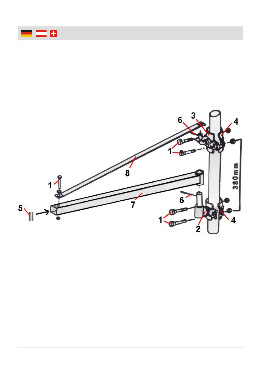
6. Befestigen Sie den kleinen Scharnierstift (3) und die zweite Rohrmanschette
(4) mit zwei Sechskantschrauben (1) oberhalb des großen Scharnierstiftes.
7. Hängen Sie nun den Stützarm (8) mit der großen Bohrung am kleinen
Scharnierstift ein und sichern Sie die Verbindung mit einem Splint (6).
8. Richten Sie die Höhe der oberen Rohrmanschette und des Stützarmes so
aus, dass der Abstand zwischen Stützarmaufhängung (8) und Vierkantausle-
ger (7) genau 380 mm beträgt.
9. Ziehen Sie nun die Schrauben an den Rohrmanschetten mit mindestens
70 Nm an.
10. Verbinden Sie den Stützarm (8) mit dem Vierkantausleger (7).
11. Plazieren Sie zuerst die Stabilisierungshülse (5) innerhalb des Vierkantausle-
gers auf Höhe der vorderen Bohrung.
Die Hülse verhindert, dass durch den Schraubenanpressdruck die Rohre
verformt werden.
12. Schieben Sie eine Sechskantschraube durch die Bohrung des Stützarms und
die Bohrung im Vierkantausleger und ziehen Sie die Schraube an.
Die Schraube (1) muss durch die Bohrungen von Schwenkarm und Vierkant-
ausleger und auch durch die Stabilisierungshülse (5) geführt werden.
Betrieb
Nach der Montage und vor dem ersten Einsatz sollten unbedingt einige Probeläu-
fe vorgenommen werden. Beginnen Sie ohne Last und steigern Sie die Last
kontinuierlich bis zur maximal zulässigen Last, die entweder durch den Schwenk-
arm oder durch den Seilhebezug vorgegeben ist.
Halten Sie dabei im Blick, ob die Konstruktion den Belastungen gewachsen ist.
Überprüfen Sie den festen Sitz der Schraubverbindungen.
Reinigung und Wartung
Setzen Sie den Schwenkarm nicht dauerhaft der Nässe aus.
Um den Schwenkarm beweglich zu halten, sollten die Scharniere von Zeit zu
Zeit gefettet werden.

5
Safet
y
Notes
Persons with limited physical, sensorial or mental abilities are not allowed to
use the unit, unless they are supervised for their safety by a qualified person
or are briefed by the responsible person how to use the unit.
The swing arm is intended to be used with a winch and is only allowed to be
used for the intended purpose.
Do not overload the swing arm. Only use the cable winch up to its maximum
load capacity. Concerning this, see Technical Data.
It is forbidden to use the swing arm to transport persons.
Take care that no persons stay under the swing arm or under the winch.
Never stand or work beneath a raised load.
The unit is not designed for continuous, professional use.
Modifications on the swing arm are not allowed.
Please also mind the safety notes of the cable winch manufacturer.
If the unit has damages as e. g. cracked welds or bent parts, do not use it and
have it repaired by a professional or contact our customer service. Do not try
repairing it yourself.
Please mind the included General Safety Notes and the following
safety notes to avoid malfunctions, damages or physical injuries:

6
Start-u
p
Mounting
To attach the swing arm you need a steel pipe with a diameter of 48 mm and a
wall thickness of at least 3 mm. The pipe must be solidly mounted to withstand
the forces involved. When in doubt, consult a professional.
If the winch is mounted at the outer end of the arm, a maximum weight of 600 kg
can be attached.
1. Use two hex screws (1) to attach the sleeve (4) and the large hinge pin (2) to
the steel pipe.
2. Before tightening the screws, align the hinge pin to the desired height of the
swing arm.
3. Apply lubricating grease to the hinge pin
4. Slide the square tubing arm (7) over the pin and guide the securing pin (6)
through the hole in the hinge pin.
5. Spread the wires of the pin to prevent it from falling out.

7
O
p
eration
|
Cleanin
g
and Maintenance
6. Now mount the small hinge pin (3) and the second sleeve (4) with two hex
screws (1) above the larger hinge pin.
7. Hook the large borehole of the support arm (8) in the small hinge pin and
secure the joint with a pin (6).
8. Adjust the upper sleeve in such a way that the distance between the hinge of
the support arm (8) and the square tube arm (7) is exactly 380 mm.
9. Tighten all screws on the sleeves with at least 70 Nm.
10. Now attach the support arm (8) to the square tube arm (7).
11. First place the stabilising sleeve (5) inside the square tube arm in height of
the front drill hole.
The sleeve avoids deforming of the tubes by the screw clamping force.
12. Push a hex screw (1) through the borehole in the support arm and through
the drilling in the square tube arm and tighten it.
The screw (1) must be guided through the drillings of the swing arm and
square tube arm and also through the stabilising sleeve (5).
Operation
After installation and before first use, take absolutely some test runs. Start out
without load and gradually work up to the highest load, which is determined by the
maximum load of the arm or the winch.
Monitor while test running, if the construction of the swing arm is up to its load
and check, if the screw connections are fitted firmly.
Cleaning and Maintenance
Do not expose the swing arm continuously to moisture.
To keep the hinges well lubricated, regularly apply grease.

8
Notizen
|
Notes

V
Notizen
|
Notes

Gestaltung urheberrechtlich geschützt VI © Westfalia 09/09
Notizen
|
Notes
Deutschland Österreich
Westfalia Westfalia
Werkzeugstraße 1 Moosham 31
D-58093 Hagen A-4943 Geinberg OÖ
Telefon: (0180) 5 30 31 32 Telefon: (07723) 4 27 59 54
Telefax: (0180) 5 30 31 30 Telefax: (07723) 4 27 59 23
Internet: www.westfalia.de Internet: www.westfalia-versand.at
Schweiz UK
Westfalia Westfalia
Utzenstorfstraße 39 Freepost RSBS-HXGG-ZJSC
CH-3425 Koppigen 8 Fairfax Road, N. Abbot TQ12 6UD
Telefon: (034) 4 13 80 00 Phone: (0844) 5 57 50 70
Telefax: (034) 4 13 80 01 Fax: (0870) 0 66 41 48
Internet: www.westfalia-versand.ch Internet: www.westfalia.net
Kundenbetreuun
g
|
Customer Services
Werter Kunde,
bitte helfen Sie mit, Abfall zu vermeiden.
Sollten Sie sich einmal von diesem Artikel trennen wollen, so bedenken Sie
bitte, dass viele seiner Komponenten aus wertvollen Rohstoffen bestehen und
wiederverwertet werden können.
Entsorgen Sie ihn daher nicht in die Mülltonne, sondern führen Sie ihn bitte
Ihrer Sammelstelle für Wertstoffe zu.
Dear Customer,
Please help avoid waste materials.
If you at some point intend to dispose of this article, then please keep in mind
that many of its components consist of valuable materials, which can be
recycled.
Please do not discharge it in the rubbish bin, but check with your local council
for recycling facilities in your area.
Entsor
g
un
g
|
Dis
p
osal
This manual suits for next models
1
Table of contents
Languages:
Other Westfalia Winch manuals

Westfalia
Westfalia Electric Winch User manual

Westfalia
Westfalia 24 99 20 User manual

Westfalia
Westfalia 26 67 75 User manual

Westfalia
Westfalia 32 15 21 User manual

Westfalia
Westfalia 80 29 68 User manual

Westfalia
Westfalia 80 29 47 User manual

Westfalia
Westfalia 812217 User manual

Westfalia
Westfalia 82 45 37 User manual

Westfalia
Westfalia 72 83 52 User manual

Westfalia
Westfalia 824536 User manual