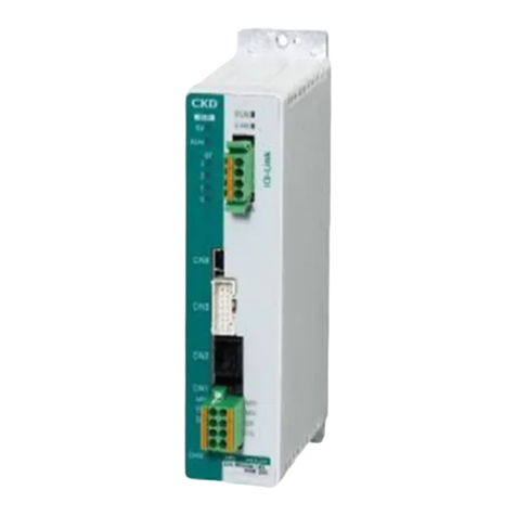
CKD OMC2-10 User manual

SM-50661-A
Instruction Manual
Sequential control component for pulse jet valve
OMC2-10
OMC2-6
●Before operating the product, read this
instruction manual without fail.
Among all, carefully read safety-related
descriptions.
●Keep this instruction manual in a safe place so
that it can be referred to whenever necessary.
CKD Corporation

SM-50661-A
- 1 -
For safe operation of product
1. General precautions
This instruction manual covers basic items related to the handling of the product
including an outline of actions, control method, cable connection procedure and
maintenance.
Description about cable connection procedures in this instruction manual is for
electricians.
Request professional electricians for the work.
Carefully read before designing or fabricating to assure safety of the machine and
equipment and handle the product adequately.
Full performance may not be achieved in some applications or methods, or even
accidents may be caused. Product specification check and determination of the
operation method matching the customer's applications and methods are up to the
customer.
2. Safety precautions
Handling precautions are provided at places so that personal injuries and damage to
property can be avoided. Absolutely follow these precautions.
While various safety measures are provided for the product, handling errors will cause
accidents. To avoid errors, read through the instruction manual and be familiar
with the description when operating the product.
We will not assume responsibility for accidents caused by handling errors.
Use care of the following in addition to other handling precautions written in this
manual.
CAUTION Electric shock will hit you if you touch wiring connections (bare
live parts) of the pulse jet controller.
Be sure to turn the power off when conducting wiring work.
Keep away from parts other than switches, terminal blocks and
jumpers.
!

SM-50661-A
- 2 -
[ Contents ]
1. Outline of Actions---------------------------------------------------- 3
2. Name of Each Part --------------------------------------------------- 4
3. Fixing Method --------------------------------------------------------- 5
4. Wiring Method--------------------------------------------------------- 5
5. Pre-operation Check ------------------------------------------------ 7
6. Adequate Operation Method ------------------------------------- 7
7. Initial Setting and Action
7.1 Independent action --------------------------------------------- 8
7.2 Master/Slave action --------------------------------------------- 9
7.3 Specifying the number of steps ---------------------------- 10
7.4 Pulse ON time setting------------------------------------------ 11
7.5 Pulse OFF time setting ---------------------------------------- 12
7.6 Double hammering setting ----------------------------------- 13
7.7 Interval timer setting ------------------------------------------- 14
7.8 Stopping action -------------------------------------------------- 16
8. Specifications of Product ----------------------------------------- 18
9. Inspection -------------------------------------------------------------- 19
10. Accessories------------------------------------------------------------ 19

SM-50661-A
- 3 -
1. Outline of Actions
The pulse jet controller conducts sequence control of pulse jet valves of the dust collector
according to the number of valves.
You can designate an arbitrary number of steps between 1 and 10 (1 and 6) according to
the number of connected valves, and indicators show the operating valves.
The ON and OFF time can be designated independently of each other as shown in Fig
1-1.
(Fig. 1-1)
The pulse ON time and pulse OFF time of the second and later steps are the same
as those of the first step.
First step Second step
Pulse ON
time
Pulse OFF
time
Variable
between 0.01
and 990
seconds
Variable
between 1 and
990 seconds

SM-50661-A
- 4 -
2. Name of Each Part
①DIP switch (SW3) Switches among the independent, master and slave actions.・・・・・・・> 8,9
②DIP switch (SW2) Specify double hammering or interval timer. ・・・・・・・・・・・・・・・・・・・・・> 13,14
③LED(LED1 to 10(6)) Lights up upon a pulse.
④Jumper(J1 to 5) Specify each function. (J6: Unused)・・・・・・・・・・・・・・・・・・・・・・・・・・・・・> 11 to 17
⑤DIP switch (step) Specify the number of steps.・・・・・・・・・・・・・・・・・・・・・・・・・・・・・・・・・・・> 10
⑥DIP switch (ON x 10) Specify the pulse ON time.・・・・・・・・・・・・・・・・・・・・・・・・・・・・・・・・・・・・・> 11
⑦DIP switch (ON x 1) Specify the pulse ON time.・・・・・・・・・・・・・・・・・・・・・・・・・・・・・・・・・・・・・> 11
⑧DIP switch (OFF x 10) Specify the pulse OFF time.・・・・・・・・・・・・・・・・・・・・・・・・・・・・・・・・・・・・> 12
⑨DIP switch (OFF x 1) Specify the pulse OFF time.・・・・・・・・・・・・・・・・・・・・・・・・・・・・・・・・・・・・> 12
⑩LED (POWER) Keeps lit while the power is turned on.
⑪Terminal block (TB4) Ganged operation and stop input terminal・・・・・・・・・・・・・・・・・・・> 9,16
⑫Power switch Power switch
⑬Fuse 250V 3A
⑭Terminal block (TB1) Valve output terminals (SV1 to 6) and AC input terminal・・・・・・・・・・・・> 6
⑮Terminal block (TB2) Valve output terminals (SV7 to 10) (Not provided for OMC2-6)

SM-50661-A
- 5 -
3. Fixing Method
CAUTION : Install the product free from dust and water splashes.
Round holes (at four places: a) are provided for the pulse jet controller as shown in Fig.
3-1. Use M4 screws to fix securely. Use accessory spacers when necessary.
(Fig. 3-1)
4. Wiring Method
CAUTION : Be sure to turn the source power off when conducting.
①Terminal block (for TB4) cable
Use 0.75mm2to 2mm2vinyl sheath cable.
②Termination method
Install a crimp terminal at the terminal of the AC input and valve output (TB1 and TB2)
cables.
Applicable crimp terminal (example)
●The applicable cable varies
according to the crimp
terminal.
!
4-Ø4.5(a)
130
(Mounting pitch)
Ø
4.2
Ø
8
20
130 (Mounting pitch)
Accessory spacer (4 pieces)
!
Manufacturer Model Applicable cable
J.S.T. Mfg. V2-MS3 1.04 to 2.63mm
2

SM-50661-A
- 6 -
③AC source voltage input and grounding
CAUTION : Connect the grounding cable without fail to avoid electric shock.
Check the voltage of the valve to be used, and connect the conforming voltage to the AC
input terminals (V1 and V2).
V1 V2 FG
(Fig. 4-1)
④Valve output
Connect by the number of valves in order at the valve output terminal block, starting at SV1.
(Fig. 4-2)
CAUTION : Fit the transparent terminal cover in the original state after
connecting cables. (TB1 Only)
100VAC to 220VAC
Ground
SV1 SV2 SV3 SV4 SV5 SV6 COM SV7 SV8 SV9 SV10
SV1 SV2 SV3 SV4 SV5 SV6 SV7 SV8 SV9 SV10
!
!

SM-50661-A
- 7 -
5. Pre-operation Check
5.1 Appearance check
CAUTION : Turn the source power off.
● Check that the pulse jet controller is securely fixed.
5.2 Wiring check
CAUTION Turn the source power off.
After checking wiring, fit the terminal cover
in the original state. (TB1 Only)
● Check that screws at the terminal block are tight.
● Check the source voltage, using a multimeter or the like.
Operate the product at voltage fluctuation within ±10% of the rated voltage.
6. Adequate Operation Method
CAUTION Do not touch with wet hands.
To change the setting at the jumper or DIP switch, turn the
power switch off without fail to avoid electric shock.
Do not disassemble or remodel.
Do not insert a socket to jumper J6.
● Do not operate the product at ambient temperatures below -10°C or above +60°C.
!
!
!

SM-50661-A
- 8 -
7. Initial Setting and Action
7.1 Independent action
①Outline
Operate the valve according to the set step with a single pulse jet controller.
②Set DIP switch (SW3) as shown in Fig. 7-1.
(Use the tip of a precision regular screwdriver or the like to manipulate.)
(Fig. 7-1)
③Action sequence
(Fig. 7-2)
●SVn: Valve of the specified number of steps
OFF
ON
ON
OFF
Power supply
SV1
SV2
SV3
SVn
1 cycle The cycle is
repeated.
ON time
OFF time
Power SW ON
(Valve output start)
Power SW OFF
(Valve output stop)

SM-50661-A
- 9 -
7.2 Master/Slave action
①Outline
While a single pulse jet controller can issue up to 10 output points, expansion can be
made to 20 or 30 points through connection shown in Fig. 7-3.
(Fig. 7-3)
②Set DIP switch (SW3) as shown in Fig. 7-4.
(Use the tip of a precision regular screwdriver or the like to switch.)
(Fig. 7-4)
Master setting
(Controller No. 1)
OFF
ON
OFF
OFF
Controller No. 1
Master setting
Controller No. 2
Slave setting
Controller No. n
Slave setting
Slave setting
(Controller No. 2 to No. n)

SM-50661-A
- 10 -
③Action sequence
● Turn the master and slave on simultaneously or turn the slave on first.
(Fig. 7-5)
●SVn: Valve of the specified number of steps
7.3 Specifying the number of steps
①Adjust the DIP switch (step) to the number of valves.
1 →1 valve (SV1)
2 →2 valves (SV1, SV2)
0 →10 valves (SV1 to SV10)
Example: Step 10
●With OMC2-6, settings 7, 8, 9 and 10 indicate six
valves.
●The number of steps must be specified at all controllers
both in the independent action mode and master/slave
action mode.
Power supply
No.1
(Master)
No.2
(Slave)
No.n
(Slave)
P.8 (Fig. 7-2)
1 cycle
Power SW ON
(Valve output start)
( f i g. 7 - 6)
ス テ ッ プ
5
2
3
4
7
8
6
9
0
1

SM-50661-A
- 11 -
7.4 Pulse ON time setting
①Use the DIP switch (ON) to specify the pulse ON time.
(Use the tip of a precision regular screwdriver or the like.)
●Specify in the two-digit number x 0.01 seconds (time range).
Example: 0.25 sec.
②The time range changes according to jumper combination (J3 and J4).
J3 J4 Time range Setting time
OFF OFF × 0.01 sec. 0.01 to 0.99 sec.
OFF ON × 0.1 sec. 0.1 to 9.9 sec.
ON OFF × 1 sec. 1 to 99 sec.
ON ON × 10 sec. 10 to 990 sec.
● Insert a socket over jumper pins to activate.
(This rule applies to the other jumpers, too.)
(Fig. 7-8)
Socket
Jumper pin
( f i g . 7- 7 )
O N
× 1 0 × 1
5 5
7
8
6
9
0
4
1
0
2
3
4
1
2
3
7
8
6
9

SM-50661-A
- 12 -
7.5 Pulse OFF time setting
①Use the DIP switch (OFF) to specify the pulse OFF time.
(Use the tip of a precision regular screwdriver or the like.)
● Specify in the two-digit number x 1 second (time range).
Example: 30 sec.
②The time range changes according to the setting of jumper (J2).
J2 Time range Setting time
OFF × 1 sec. 1 to 99 sec.
ON × 10 sec. 10 to 990 sec.
( f i g . 7 - 9 )
5 5
× 1 0× 1 0 0 × 1
O F F
0
2
3
4
1
2
3
4
1
7
8
7
8
6
9
0
6
9

SM-50661-A
- 13 -
7.6 Double hammering setting
①Use DIP switch (SW2) to specify double or single hammering.
Example: Double hammering at SV3 and 6 only
(Fig. 7-10)
②Action sequence
(Fig. 7-11)
● SW2 is common for "double hammering" and "interval timer" settings, and it can be
used for either purpose. For details, refer to Section "7.7 Interval Timer Setting."
Double hammering
Double hammering

SM-50661-A
- 14 -
7.7 Interval timer setting
①Insert jumper (J5) to specify the interval timer (pause in each cycle). (1 to 99 min.)
J5 Function of SW2
OFF Double hammering
ON Interval timer
②Specify the interval timer with DIP switch (SW2).
● The interval timer is the sum of units digit and tens digit shown in Table 7-12.
● The settings shown in other than Table 7-12 is 0 minutes.
Table 7-12
Element number of SW2 Interval timer
(units digit)
Element number of SW2 Interval timer
(tens digit)
1 2 3 4 5 6 7 8
OFF OFF OFF OFF 0 min. OFF OFF OFF OFF 0 min.
ON OFF OFF OFF 1 min. ON OFF OFF OFF 10 min.
OFF ON OFF OFF 2 min. OFF ON OFF OFF 20 min.
ON ON OFF OFF 3 min. ON ON OFF OFF 30 min.
OFF OFF ON OFF 4 min. OFF OFF ON OFF 40 min.
ON OFF ON OFF 5 min. ON OFF ON OFF 50 min.
OFF ON ON OFF 6 min. OFF ON ON OFF 60 min.
ON ON ON OFF 7 min. ON ON ON OFF 70 min.
OFF OFF OFF ON 8 min. OFF OFF OFF ON 80 min.
ON OFF OFF ON 9 min. ON OFF OFF ON 90 min.
Example: 35 minutes ( marks in Table 7-12)
(Fig. 7-13)
The interval timer is not accepted at
the controller operating in the slave
action mode.
Setting of units digit Setting of tens digit Unused

SM-50661-A
- 15 -
③Action sequence
③-1. Independent action
(Fig. 7-14)
③-2. Master/Slave action
(Fig. 7-15)
●SVn: Valve of the specified number of steps
1 cycle
Power supply
Power SW ON
A: Interval timer
Power supply
No.1
(Master)
No.2
(Slave)
P.8 (Fig. 7-2)
1 cycle
Power SW ON A: Interval timer

SM-50661-A
- 16 -
7.8 Stopping action
①Short circuit across C and C2 of the terminal block (TB4) to turn off the valve output.
Open to output from the next step. (Immediate stop)
ON: Stop (valve output OFF)
(Fig. 7-16. Immediate stop/Cycle stop in independent action mode)
ON: Stop (valve output OFF)
(Fig. 7-17. Immediate stop in master/slave action mode)
②Action sequence for immediate stop
(Fig. 7-18)
Connect cables to stop
the master and slave
simultaneously.
Master Slave
Stop
Stopped

SM-50661-A
- 17 -
③Insert the jumper (J1) to stop at each cycle.
(Cycle stop)
J1 Stopping action
OFF Immediate stop
ON Cycle stop
●Connect the stop input to the master only in the master/slave action mode after
cycle stop.
ON: Stop (valve output OFF)
(Fig. 7-19. Cycle stop in master/slave action mode)
④Action sequence at cycle stop
(Fig. 7-20)
Cycle stop is not accepted at the controller
operating in the slave action mode.
Master Slave
Stop
No.1
(Master)
No.2
(Slave) 1 cycle Stopped

SM-50661-A
- 18 -
8. Specifications of Product
Number of output steps: 6 (OMC2-6), 10 (OMC2-10)
Source voltage: 100 to 220VAC ±10% 50/60Hz
Current consumption: Within 5VA (controller only)
Power supply fuse: 3A 250V
Operating ambient temperature: -10 to +60°C
Relative humidity: 30 to 80%RH
Storage ambient temperature: -20 to +70°C
Pulse ON time setting range: (01 to 99) × (0.01sec. or 0.1sec. or 1sec. or 10sec.)
Pulse OFF time setting range: (01 to 99) × (1sec. or 10sec.)
Setting time accuracy: (Setting time) × (±5%) + 10msec or less
Action mode
a) Independent: Continuous operation mode of single unit
b) Interlock: Series connection interlock mode of controllers operating in
master and slave modes
Pulse repetition frequency: Single/Double hammering (Interval time setting mode: single
hammering only)
Stop: Immediate stop/Cycle stop (either one selected)
Interval time: 1 to 99 min. (valid only in single hammering mode)
Isolation resistance: 10MΩminimum (500VDC)
Dielectric strength: 1500VAC for 1 min.

SM-50661-A
- 19 -
9. Inspection
Perform periodic inspection every six months to operate the product in the best
condition.
For details of inspection, refer to Section 5 "Pre-operation Check."
10. Accessories
The following parts are attached as accessories.
Part name Model Quantity
Spacer CX-420 made by Hirosugi Keiki (marketed product) 4
Jumper socket Model XJ8A-0211 made by Omron (marketed product) 5
Fuse FGMB 3A 250V made by Fuji Tanshi (marketed product) 1
This manual suits for next models
1
Table of contents
Other CKD Controllers manuals

CKD
CKD ECG Series User manual

CKD
CKD SC1-6N User manual

CKD
CKD RCS2 Series User manual

CKD
CKD GCKW Series User manual

CKD
CKD ER300 User manual

CKD
CKD AX1000T Series User manual

CKD
CKD KBX-10E-U Series User manual

CKD
CKD FLCR-G Series User manual

CKD
CKD ECR Series User manual

CKD
CKD KBX-50-UR Series User manual