Water Specialist WS2H User manual

Water Specialist
WS2H and WS3 Control Valve
Manual
HYDROCARBONS SUCH AS VASELINE®, PETROLEUM JELLY, KEROSENE, BENZENE,
GASOLINE, ETC., WILL DAMAGE PRODUCTS THAT CONTAIN O-RINGS OR PLASTIC
COMPONENTS. EXPOSURE TO SUCH HYDROCARBONS MAY CAUSE THE PRODUCTS
TO LEAK. DO NOT USE CLACK CONTROL VALVE PRODUCT(S) ON WATER SUPPLIES
THAT CONTAIN HYDROCARBONS SUCH AS KEROSENE, BENZENE, GASOLINE, ETC.

Page 2 WS2H and WS3 Manual

WS2H and WS3 Manual Page 3
General Specications and Pre-Installation Checklist .................................................... 4
Wiring for custom Power Adapter .................................................................................... 5
Custom Meter Wiring ....................................................................................................... 5
Main PC Board................................................................................................................. 6
Typical System Examples................................................................................................. 7
Button Function and Programming Key Sequence.......................................................... 9
Programming Quick Reference ...................................................................................... 10
Typical User Screens...................................................................................................... 12
Setting Time of Day and Date ........................................................................................ 14
Notications ................................................................................................................... 14
Errors.............................................................................................................................. 14
Main Menu...................................................................................................................... 15
System Setup Screens................................................................................................... 16
Cycle Setup Screens...................................................................................................... 21
Expansion Setup Screens .............................................................................................. 23
Installer Setup Screens .................................................................................................. 26
Diagnostic Screens ........................................................................................................ 28
Valve History................................................................................................................... 31
Custom Motorized Drive Timing..................................................................................... 32
Modbus Information ....................................................................................................... 33
Installation ...................................................................................................................... 34
Installation Summary...................................................................................................... 37
Cycle Positions / Flow Diagrams.................................................................................... 38
Front Cover and Drive Assembly.................................................................................... 41
WS2H Drive Cap Assembly, Downow Piston, Regenerant Piston,
Spacer Stack Assembly, Drive Back Plate, Main Body and Meter ................................ 42
WS3 Drive Cap Assembly, Downow Piston, Regenerant Piston,
Spacer Stack Assembly, Drive Back Plate and Main Body............................................ 43
WS2H and WS3 Brine Valve Body and Injector Components ....................................... 44
Standard Injector Graphs............................................................................................... 45
V3064 WS2H/2QC 4 INCH BASE ASY........................................................................... 47
V3055 WS2H/2QC 6 INCH FLANGE BASE ASY............................................................ 47
WS2H/2QC SIDE MOUNT BASE ASSEMBLY................................................................ 47
V3260BSPT-02 WS2H/2QC SIDE MOUNT BASE BSPT ASSEMBLY ............................ 47
Drain Line Flow Controls ................................................................................................ 48
M X F STAINLESS STEEL, 0.7 – 150 GPM..................................................................... 49
M X F STAINLESS STEEL, 9 – 225 GPM........................................................................ 50
Drain Line Flow Control Washers ................................................................................... 51
WS2H/ WS3 Trouble Shooting Guide............................................................................. 52
TABLE OF CONTENTS

Page 4 WS2H and WS3 Manual
GENERAL SPECIFICATIONS AND PRE-INSTALLATION CHECKLIST
TABLE 1
Minimum/Maximum Operating Pressures 20 psi (138 kPa) -125 psi (862 kPa)
Minimum/Maximum Operating
Temperatures 40°F (4°C) – 110°F (43°C)
Power Adapter:
Supply Voltage
Supply Frequency
Output Voltage
Output Current
U.S. and International
120/230V AC
50/60 Hz
24V DC (see Table 2)
800 mA
No user serviceable parts are on the PC board, the motor, or the Power adapter. The means of disconnection from
the main power supply is by unplugging the Power adapter from the wall.
Service ow rate WS2H Valve: 125 gpm (473 lpm, 28.4 m3/h) @ 15 psig (103 kPa) drop
WS3 Valve: 250 gpm (946 lpm, 56.8 m3/h) @ 15 psig (103 kPa) drop
Backwash ow rate WS2H Valve: 125 gpm (473 lpm, 28.4 m3/h) @ 25 psig (172 kPa) drop
WS3 Valve: 220 gpm (833 lpm, 50.0 m3/h) @ 25 psig (172 kPa) drop
CV Service WS2H Valve: 32.3
WS3 Valve: 64.6
CV Backwash WS2H Valve: 25.0
WS3 Valve: 44.0
Meter:
Accuracy
Flow Range
WS2H Valve:
Internal Meter
+ 5 %
1.5 – 125 gpm
(5.7 – 473 lpm)
WS3 Valve: Optional External Meter
+ 5 %
3.5 – 350 gpm (13.3 – 1325 lpm)
Regenerant Rell Rate WS2H and WS3 Valves: Variable - Shipped from Factory with 2.2 gpm
(8.33 lpm)
Injectors WS2H & WS3 Valves: See Injector Graphs V3010-2A through 2H
Brine Line Adapters Included 1” Male NPT Elbow & ¾” x 1” Solvent Weld Elbow
Inlet, Outlet and Drain Line Openings WS2H Valve: 2” Female NPT or BSPT
WS3 Valve: 3” Female NPT or BSPT, No Groove Lock
*Distributor Tube Sizing:
WS2H Valve
WS3 Valve
Female NPT Inlet & Outlet Female BSPT Inlet & Outlet
2.375” OD (2.0” NPS)
3.5” OD (3” NPS)
+2.25” -
+2.5”
+2.5” – 2.75”
63 mm OD
90 mm OD
+57 mm - +64
mm
+64 mm - + 70
mm
Tank Connection:
WS2H Valve
WS3 Valve
4”-8UN, 6” Flange, Side Mount (2” Female NPT or BSPT)
6” Flange or Side Mount (3” Female NPT or BSPT)
Shipping Weight WS2H Valve with Meter: 50 lbs. (22.7 kg)
WS3 Valve: 57 lbs. (25.9 kg) Meter Sold Separately
PC Board Memory Nonvolatile EEPROM (electrically erasable programmable read only
memory)
Compatible with the following typical
concentrations of regenerants/chemicals
Sodium chloride, potassium chloride, potassium permanganate,
sodium bisulte, chlorine and chloramines
*Height is based off the top of tank. Installer to verify proper engagement and allowance for tank expansion

WS2H and WS3 Manual Page 5
1) Terminate end with a Molex series 2695 housing, part num-
ber 22-01-3037 and (3) Molex series 41572 (or 40445) pins,
part number 08-65-0805 (or 97-00-44).
2) Auxilliary meter must be able to operate on 5VDC
Pin 1 = +5VDC
Pin 2 (Center) = Signal
Pin 3 = Ground
3) Acceptable pulse input is .1 – 999 pulses/gallon, or
.4 –519 pulses / liter.
WIRING FOR CUSTOM POWER ADAPTER
1. Cable should be one unshielded pair of 22AWG, UV resistant
UL2464 compliant wire.
2. Connector details:
a. Terminate end with one Hirose black housing,
P/N DF3-4S-2C and four Hirose pins, P/N DF3-22SC.
b. Pin 1 = Ground from power supply (Black)
Pin 2 = Jumper to Pin 3
Pin 3 = Jumper to Pin 2
Pin 4 = +24V DC from power supply (White)
CUSTOM METER WIRING
Molex
Housing
Pin 1
Pin 1
Black wire

Page 6 WS2H and WS3 Manual
MAIN PC BOARD
Power Supply
Flow Meter
POD Display
Connection
AUX Input
COMM OUT
Drive Motor USB Port
Battery
Programming Port
Expansion port 1
Item Board label Description
1 POWER Connect to proper power supply
2 FLOW Input for the unit’s ow meter
3 REGEN Motor circuit used to power the main drive of the unit during regeneration
4 AUX DRIVE 2nd Drive circuit for factory motorized isolating valve (MAV or NoHBP)
5 BYPASS Drive circuit for factory motorized isolating valve (MAV or NoHBP)
6 AUX IN Connect to external dry contacts to control functionality based on the unit’s settings
**Wiring units inputs in parallel requires matching each units polarity**
7 DISPLAY Connection for POD display
8 USB USB connection for future use. Must use adapter cable to convert from micro-USB
connection to USB female adapter
9 COMM IN/MODBUS RJ45 communication port for communication to Master or previous Slave. Must
use straight through RJ45 cable with T-568B wiring for communication to Master or
previous Slave.
If setup as Master, can be used for Modbus communication with proper cable wiring
and RS485 communication adapter.
10 COMM OUT RJ45 communication port for communication to Slave units. Must use straight through
RJ45 cable with T-568B wiring for communication to Slave.
11 BAT1 CR2032 battery for keeping clock powered during power loss
12 EXP1 Connection for the optional expansion boards
13 EXP2 Connection for the optional expansion boards
14 DATA Factory use only
AUX Drive Motor Bypass Motor Expansion port 2
COMM IN
26
1
7
10
9
11
14
3
45
812 13
WS2H and WS3 Manual Page 7
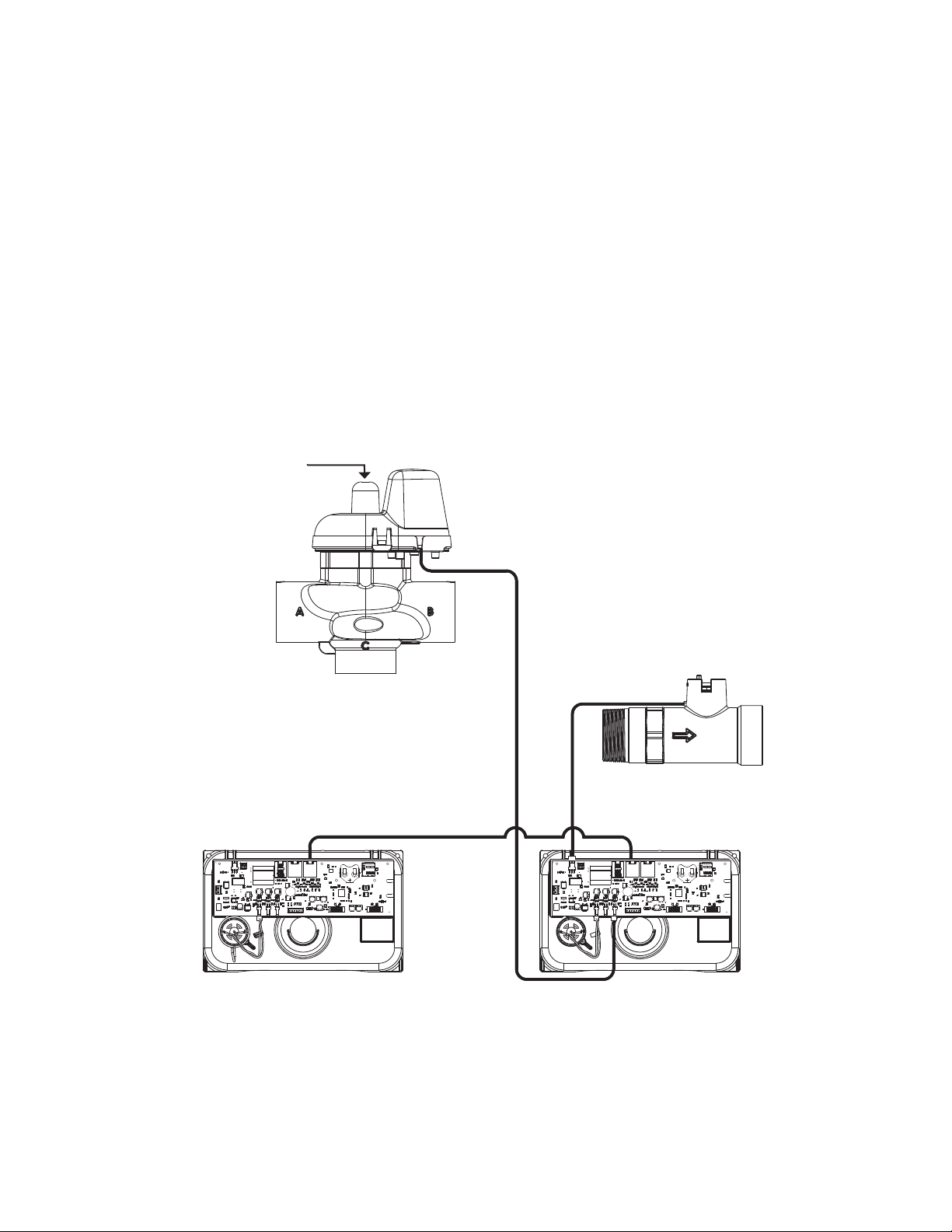
TYPICAL SYSTEM EXAMPLES
Twin Tank System, Simple Alternator (Sharing a MAV)
System consists of 2 power heads, 1 communication cable and 1 MAV
Electrical Connections:
• The MAV’s motor wire is connected to the 2-pin connector labeled BYPASS on Unit 2 (Unit B) PC board
• Using a standard straight through RJ45 cable (T-568B wiring), connect the “COMM OUT” of the MASTER control to
the “COMM IN” of the SLAVE control (See Page 6 for connector locations)
• If a single external meter is used, it should be connected to the 3-pin connector on Unit 2 (Unit B) labeled FLOW.
NOTE: When using a single external meter, “SYSTEM PULSES” and the proper pulse rate must be selected in the
programming section.
Plumbing Connections:
• To regenerate with raw/untreated water, the outlet of each unit is piped to the MAV. Port A will be piped to the Master
(Unit A) , Port B to the slave (Unit B), and Port C to the common supply outlet.
• To regenerate with soft/treated water, the inlet of each unit is piped to the MAV. Port A will be piped to the Master
(Unit A), Port B to the slave (Unit B) and Port C to the common supply outlet.
Alternator systems with a single MAV
or meter will connect to the B unit
If the piston rod is not visible, the
current path of ow is between the
“A” and “C” ports.
Port A Port B
Port C
Master (Unit A) Slave (Unit B)

Page 8 WS2H and WS3 Manual
TYPICAL SYSTEM EXAMPLES (CONTINUED)
Multi-tank System, 3 Unit shown
System consists of 3 power heads, 2 communication cables and 3 No Hard Water Bypass (Isolation) valves
Electrical Connections:
• Each unit’s isolation valve motor wire is connected to the 2-pin connector labeled BYPASS on each unit’s PC board.
• Using two standard straight through RJ45 cables (T-568B wiring), connect the “COMM OUT” of the MASTER control
to the “COMM IN” of SLAVE 1 and the “COMM OUT” of SLAVE 1 to the “COMM IN” of SLAVE 2 (See Page 6 for
connector locations)
Plumbing Connections:
• To regenerate with raw/treated water, the isolation valve is piped into the outlet of each unit.
• To regenerate with soft/treated water, the isolation valve is piped into the inlet of each unit.
Visibility of the piston rod indicates
the online status of the unit.
The piston rod drive “In” or not
visible indicates the unit is ofine,
in Standby or Regen.
Master Slave 1 Slave 2
WS2H and WS3 Manual Page 9
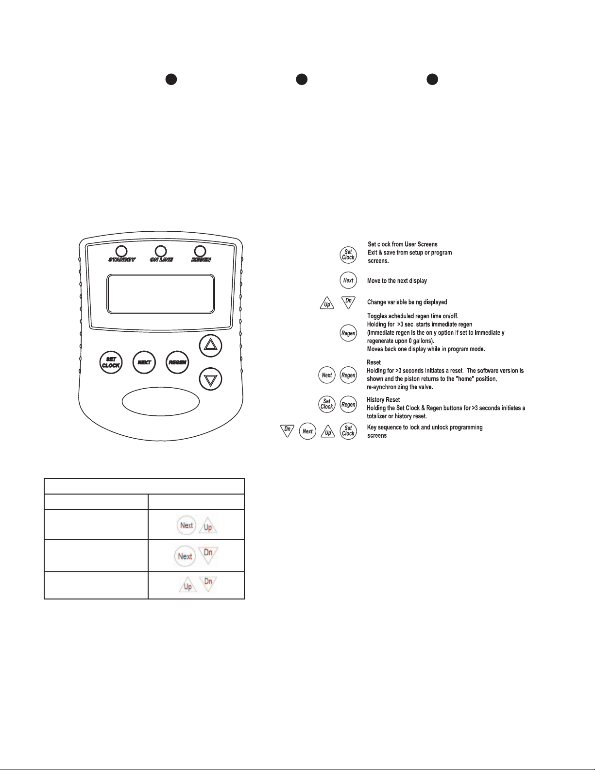
BUTTON FUNCTION AND PROGRAMMING KEY SEQUENCE
Programming Key Sequences
Programming Level Buttons
Installer
Main Setup Menu
Diagnostics and
History
Standby LED
• Signals that a unit
is not in service, or
regen
• Flashes to alert status
conditions
- 1 per second
indicates ow had
been detected
while the unit was
ofine
Online LED
• Signals that a unit is
currently in service
Regen LED
• Signals that a unit is
currently in regen
STANDBY ON LINE REGEN
Page 10 WS2H and WS3 Manual
PROGRAMMING QUICK REFERENCE
Recommended System Setup Sequence
1. Connect all wiring and communication cables.
2. Apply power.
3. Select System Setup from the Main Setup Menu.
4. Select the correct language to use in System Setup 1.
5. Select the correct unit of measurement in System Setup 2.
6. Select the correct number of units in System Setup 3.
a. Setting this value assigns master status to that unit
b. The master unit will establish communication with the remaining units and
transfer the remaining settings to them.
7. Step through the remainder of the System Setup screens and set appropriately.
8. Select Installer Setup from the Main Setup Menu and set the installer settings
appropriately.
9. Select Cycle Setup from the Main Setup Menu and set the regenerations cycles
appropriately.
10. If using the relay board, select Expansion Setup from the Main Setup Menu and
set the relays as needed.
WS2 Programming Screen Quick Reference
1. Individual screen descriptions and settings are detailed on the following pages.
2. Some screens have been omitted for clarity.
GRAINS
x1000

WS2H and WS3 Manual Page 11
PROGRAMMING QUICK REFERENCE
List Of Error Codes
Code Description
1001 No Encoder Pulses
1002 Unexpected Stall, Main Drive
1003 Run Time Too Long, Main Drive
14001 Message Queue Full
15003 Run Time Too Long, Bypass Drive
15010 Run Time Too Short, Bypass Drive
Could Not Drive Ofine
15011 Run Time Too Short, Bypass Drive
Could Not Drive Online
16001 Communication Lost With Unit 2
16002 Communication Lost With Unit 3
16003 Communication Lost With Unit 4
18000 Reset Performed
18001 Power Loss
18002 Power Restored
20001 Run time too long, AUX drive
20002 Run time too short during unwind, AUX
drive
20011 Run time too short, AUX drive
21xxx System recovery from memory error
Page 12 WS2H and WS3 Manual
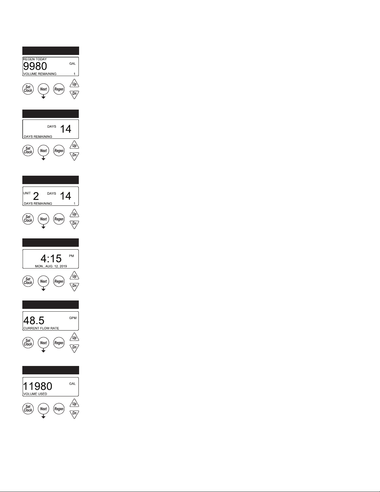
USER 1
USER 2
USER 3
USER 4
USER 5
TYPICAL USER SCREENS
USER 1 - Capacity Remaining
• Displays the units current capacity remaining
• This screen does not display on units with volumetric capacity turned off
• Can be manually decremented by holding the down arrow
USER 2 - Days Remaining, Single Unit
• Displays a single units days until a regeneration, based on the day override setting
• This screen does not display on units with day override turned off
• On systems the master unit displays the days remaining on the lead unit
• Days can be manually reduced by holding the down arrow
USER 3 - Time
• Displays the current date and time of day
USER 4 - Flow Rate, Unit
• Displays that units current ow rate
USER 5 - Volume Totalizer, Unit
• Displays the total volume since install / reset
• Re-settable to zero, while in this screen, by holding the “Set Clock” & “Regen” buttons
USER 2B USER 2B - Days Remaining, System
• The master in a system displays the days until a regeneration, based on the day override
settings.
• The displays also indicates which unit the day over ride is currently pertaining to
- Series regen systems do not display a unit as they will regenerate all units sequentially

WS2H and WS3 Manual Page 13
USER 6
USER 7
USER 6 – Flow Rate, System
• Displays the current combined ow rate of all the units in the system
• This screen does not display on single tank units, or systems with volumetric capacity turned
off
USER 7 – Volume Totalizer, System
• Displays the total volume of the system since install / reset
• Re-settable to zero, while in this screen, by holding the “Set Clock” & “Regen” buttons
• This screen does not display on single tank units
TO USER 1
TYPICAL USER SCREENS (CONTINUED)

Page 14 WS2H and WS3 Manual
SETTING TIME OF DAY AND DATE
SET TIME AND DATE
Accessed by pressing Set Clock while in the User
Screens. Use UP or DOWN arrows to scroll through
the available settings.
• REGEN TODAY
- Flashing indicates a regeneration has been manually set and can be turned off
by pressing and releasing the REGEN button
- A solid display indicates the regeneration has been scheduled by input
requirements and can’t be manually turned off
NOTIFICATIONS
• REGENERATION HOLD / REGENERATION START
- The display will ash “DP REGENERATION HOLD” or “DP REGENERATION
START”, depending on settings, to indicate an external switch closure to the
Aux. Input
• HIGH VOLUME
- Screen ashes indicating setpoint was reached when using relay outputs to
signal high water usage. All LED lights ash and the relay with that setpoint
closes.
•Screen and the relay are re-set by pressing any button
•System operates as normal behind the indicator screen.
- Only active if Timer 2 or Timer 3 is set to “Day & Gal” or “Day & Gal & System”
• NUMBER OF UNITS ERROR
- The master unit of a system would ash an error screen alerting of a loss of
communication with a unit
- Check for proper operation and connectivity of the unit specied as lost
communications
- Pressing any button will return the user to the # units set up screen to correct /
verify the value of units in the system. Exiting will re-establish communications
- Each unit of the system will regenerate, based on its settings, with hard water
bypass
ERRORS
• FUNCTIONAL ERROR
- “Error” and its code will ash on the display with a red backlight
- The unit attempts to return to service but will not regenerate until the error is
cleared
- See troubleshooting section for a description of possible error codes.
RETURN TO
NORMAL OPERATION
HIGH VOLUME
ERROR

WS2H and WS3 Manual Page 15
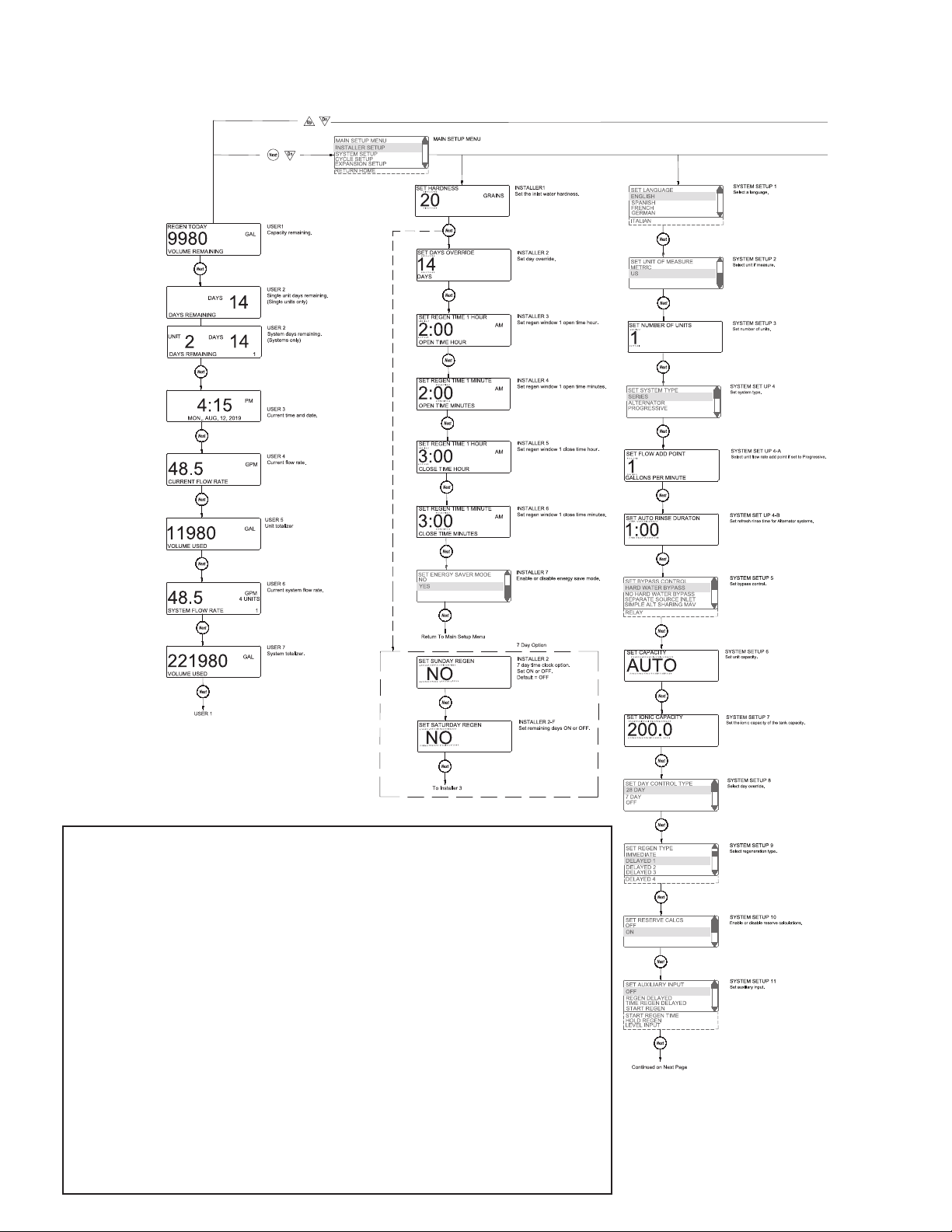
Accessed the Main Menu is done by pressing NEXT and DOWN simultaneously for >3
seconds while in one of the user screens.
INSTALLER SETUP - Setup items under the Installer Setup Screens section
SYSTEM SETUP - Setup items in the System Setup Screens section
CYCLE SETUP - Setup the primary and secondary regeneration cycles
EXPANSION SETUP - Setup expansion port options if expansion boards are installed
RETURN HOME - Return back to the user screens
• Once you are in any of the submenus, use the REGEN button to back out to the Main
Menu
• The SET CLOCK button will typically exit from any menu and return to the user screens
MAIN MENU SCREEN
MAIN MENU

Page 16 WS2H and WS3 Manual
SYSTEM SETUP 1
SYSTEM SETUP 3
SYSTEM SETUP 4
SYSTEM SETUP SCREENS
Accessed by pressing NEXT and DOWN simultaneously for >3 seconds and selecting
SYSTEM SETUP from the Main Menu.
• System setup screens will be locked on units determined to be a slaves of a system
- Slave units need to be reset, “Next” & “Regen” from any screen to have their slave
status turned off.
SYSTEM SETUP 1 – Select language
Select one of the available languages to be used when displaying text on the display.
SYSTEM SETUP 3 - Set number of units
Up to 16 units can be daisy chained using the communication in and out ports on the
controls.
SYSTEM SETUP 4 – Select System Type / Operation
This screen is only available if the number of units selected is greater than 1.
Series: All units are always online unless they are regenerating.
• Units in a series ow system will determine the need to regenerate based on:
- Any one unit reaching 0 capacity
- Day over ride
• Any one units need to regenerate will initiate sequential regenerations of all units (series
regeneration)
• Immediate systems will regenerate all unit in series upon the rst unit reaching 0 capacity
• Delayed units will regenerate during one or more of the delayed regeneration windows
Alternator: Operates the system as an alternator, having one unit off line at all times
either regenerating or fully regenerated.
• A unit in an alternator system will determine the need to regenerate based on:
- The current “lead” unit reaching 0 capacity
• Immediate systems immediately regenerate and alternate the exhausted unit with a
fully regenerated standby unit.
• Delayed systems will immediately alternate the exhausted unit with a fully regenerated
standby unit, and regenerate at the next available time slot.
- “Lead” unit regenerates based on “Lag” units
• The rst “lag” unit depleting down to 15% less than its ratio of system capacity
- 1/3 for a 4 unit; ½ for a 3 unit
- The second “lag” unit depleting down to 15% less than its ratio of system capacity
• 2/3 for a 4 unit
SYSTEM SETUP 2 SYSTEM SETUP 2 - Set unit of measure
Select either Metric units or US units for measurements.
SYSTEM SETUP 3A - Enable or disable Modbus
Enable or disable the Modbus communication protocol.

WS2H and WS3 Manual Page 17
SYSTEM SETUP SCREENS (CONTINUED)
SYSTEM SETUP 4B
SYSTEM SETUP 4A
SYSTEM SETUP 4B – Set Pre-Service Rinse
- Only available on Alternator systems
- Standby units will run through a rinse cycle before coming into service
SYSTEM SETUP 4A - Set ow add point
– Only available on Progressive systems
– Sets the ow rate which controls the point at which more valves are brought online or
taken ofine based on the ow rate
• Delayed systems will ag “lead” units based on “lag” capacity, but will not alternate with
remaining capacity until the next available delayed time.
- Day over ride
• 1 day; 1 unit will regen
• Day triggered regens will run at the time set set for the rst regeneration window
Progressive (Demand Recall): one unit is always online & additional units are added as the
online units exceed the ow add point.
• Additional units are brought online when:
- The adder point is exceeded for 30 seconds
- All required units required to cover the ow conditions will be brought into service
immediately if the ow exceeds 120% of the adder point.
• Units will go ofine when
- System ow reduces to 95% of the set adder point / unit for 1 minute.
• Any unit in a demand recall system will determine the need to regenerate based on:
- Each unit individually reaching 0 capacity
• Immediate systems will regenerate depleted units immediately after current ow
conditions allow depleted units ofine.
• Delayed units will alternate lead units immediately upon exhaustion & regenerate them
at the next available time slot.
- Day Override
• One unit will be regenerated per delayed time slot (i.e. a 4 unit system will need 4
delayed times to regenerate all units / set number of days).
• Day triggered regens will run at the time set in the rst regeneration window
- Units cannot regenerate if ow demands them to remain online
• Immediate units regen immediately after ow allows them ofine
• Delayed units regen at the next available time slot
• Day units regen at the next time slot
SYSTEM SETUP 5 SYSTEM SETUP 5 - Select bypass control
• Selections allow enabling and timing control of motorized drive
• Selection availability can vary by the type of system
• Custom timing sequences can be congured under “Custom Motorized Drive Timing” at
the end of the programming section
Hardwater Bypass
• Only available on single units
• Unit will internally bypass hard water to the service lines while in regeneration
No Hardwater Bypass
• Each unit has isolation to control system operation and will not supply service water
during regeneration
• Drive timing will bring the unit into service during ll

Page 18 WS2H and WS3 Manual
SYSTEM SETUP 7 SYSTEM SETUP 7 - Set the ionic capacity of the tank
• Only available for US based measurements
• Used for auto caculation of unit capacity
SYSTEM SETUP 6 – Set unit capacity
• Only available for US based measurements
• Allows for automatic calculation of tank capacity or user entered capacity
SYSTEM SETUP 6
SYSTEM SETUP SCREENS (CONTINUED)
SYSTEM SETUP 8 - Day override control
• 28 day time clock: Used to regenerate units based on a set number of days between
regenerations
• 7 Day Time Clock: Used to control regeneration based on specic days
• OFF: Days have no control on regenerations, and will not be a selection if volumetric
capacity is set to OFF
SYSTEM SETUP 8
Separate Source
• Each unit has isolation to control system operation and will not supply service water during regeneration
• Drive timing will keep units isolated through the entire regeneration sequence
Simple Alt Sharing MAV
• Only available when set to a 2 unit alternator
• A “Simple 2 Unit” shares one MAV to be electrically connected to the bypass connection of the “B” (slave) unit
Relay
• Only available when when the optional relay exansion module is installed and one or both of the relays is set for
Standby
• Isolation will be done through the optional relay expansion module and does not initialize the BYPASS motorized
drive circuit
Simple Alt Sharing MAV
• Only available when set to a 2 unit alternator
• A “Simple 2 Unit” shares one MAV to be electrically connected to the bypass connection of the “B” (slave) unit
WS2H and WS3 Manual Page 19
SYSTEM SETUP SCREENS (CONTINUED)
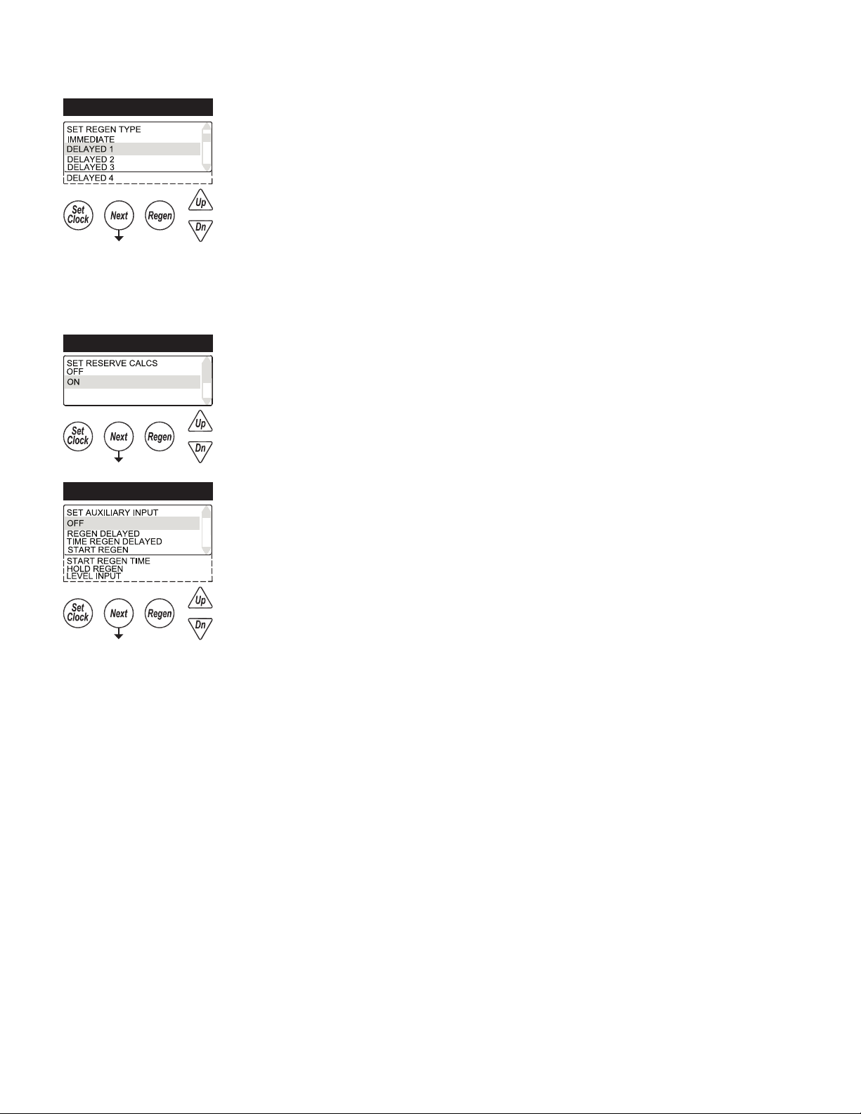
SYSTEM SETUP 9 SYSTEM SETUP 9 - Regeneration control
Delayed 1 – 4
• Delays regeneration of units upon reaching 0 gallons capacity
• Allows setting of up to 4 regeneration windows per day
• Systems with delayed regen will remove a unit from service based upon 0 capacity and
regenerate at the scheduled regen time.
- Any unit needing regeneration while the window of time is available will be able to
regenerate. Only one unit will regen at a time
• Day driven regens will regen at the Delayed 1 window time
• Depleted units will regen at the next available delayed time slot
Immediate-Immediate regeneration of units upon reaching 0 capacity
-Series regeneration systems set to Immediate will sequentially regenerate all units at the
delayed time based on day override
SYSTEM SETUP 10 SYSTEM SETUP 10 – Automatic reserve calculation
This screen will not display on units set to Immediate, capacity set to Off, or any multi-unit
systems
On: Unit will regenerate before reaching 0 capacity, based on previous usage trends
Requires delayed regeneration
OFF: Regeneration is scheduled after reaching 0 capacity
SYSTEM SETUP 11 SYSTEM SETUP 11 - Auxiliary Input
OFF
• Auxiliary input is disabled
REGEN DELAYED
• Control will immediately schedule a regen upon switch closure
• Systems follow “Delayed Logic” regenerating agged units in available time slots
TIME REGEN DELAYED
• Control will immediately schedule a regeneration upon accumulating 2 minutes of
intermittent switch closures
• Systems follow “Delayed Logic” regenerating agged units in available time slots
START REGEN
• Control will start an immediate regeneration upon switch closure
• Systems follow “Immediate logic” regenerating all agged units sequentially
START REGEN TIME
• Control will immediately regenerate upon accumulating 2 minutes of intermittent switch
• Systems follow “Immediate logic” regenerating all agged units sequentially
HOLD REGEN
• Regeneration will not be allowed as long as there is switch closure
- On0 units will regenerate immediately after the hold switch opens
- Delayed regenerations will be delayed until the next scheduled time if the hold is active
when the scheduled time passes
LEVEL INPUT
• Only available on single units
• External switching can be used to control the On Line / Standby status
- Switch closure will trigger the unit to go to a standby condition

Page 20 WS2H and WS3 Manual
SYSTEM SETUP 13 SYSTEM SETUP 13– Auxiliary Drive
• Selections allow enabling and timing control of the Auxilliary motorized drive circuit
• Requires a factory motorized drive to be connected to the AUX DRIVE connector
• Custom timing sequences can be congured under “Custom Motorized Drive Timing” at
the end of the programming section
Off
• The auxiliary drive output is disabled
No Hard Water Bypass
• Each unit has isolation to control system operation and will not supply service water
during regeneration
• Drive timing will bring the unit into service during ll
Separate Source
-Each unit has isolation to control system operation and will not supply service water
during regeneration
-Drive timing will keep units isolated through the entire regeneration sequence
SYSTEM SETUP SCREENS (CONTINUED)
SYSTEM SETUP 11A - Level Input option selected
Set a time duration of switch closure when Level option is selected
SYSTEM SETUP 12 - Meter Size Selection
2” METER: Setting for using a factory 2” meter
3” METER: Setting for using a factory 3” meter
VARIABLE METER: Used to set meter input off custom pulse rate, typically for non-factory
meters
VARIABLE SYSTEM METER: Only available on 2 unit alternators. The system shares 1
external meter which is connected to the slave unit’s meter connection.
3” SYSTEM METER: Only available on 2 unit alternators. The system shares 1 external
meter which is connected to the slave unit’s meter connection.
SYSTEM SETUP 12A SYSTEM SETUP 12A - Set Meter Pulses / Gallon
-Only displays if “VARIABLE METER” or “VARIABLE SYSTEM METER” is selected in the
previous screen
-Set to the desired pulse rate of the installed metering device
SYSTEM SETUP 12
SYSTEM SETUP 11A
SET METER PULSES
8.0
PULSES PER GALLON
SET METER PULSES
8.0
PULSES PER GALLON
Other manuals for WS2H
1
This manual suits for next models
1
Table of contents
Other Water Specialist Control Unit manuals

Water Specialist
Water Specialist WS2HF User manual

Water Specialist
Water Specialist WS1TC Guide

Water Specialist
Water Specialist WS1CC Guide

Water Specialist
Water Specialist WS1CT User manual

Water Specialist
Water Specialist WS1TT User manual

Water Specialist
Water Specialist WS1HR User manual

Water Specialist
Water Specialist EE User manual

Water Specialist
Water Specialist CK User manual


