Water Specialist CK User manual

Water Specialist CK and EQ
Control Valve
Programming and Cover Drawing Manual

Page 2 CK and EQ Manual

CK and EQ Manual Page 3
Table of Contents
CK Front Cover and Drive Assembly............................................................................................................................4
OEM General Programming Instructions ......................................................................................................................5
OEM Cycle Sequence....................................................................................................................................................7
OEM Softener System Setup .......................................................................................................................................13
Setting Options Table...................................................................................................................................................16
OEM Filter System Setup ............................................................................................................................................ 17
Installer Display Settings .............................................................................................................................................20
User Display Settings...................................................................................................................................................21
Diagnostics...................................................................................................................................................................24
Valve History ...............................................................................................................................................................26

Page 4 CK and EQ Manual
CK and EQ Front Cover and Drive Assembly
Drawing No. Order No. Description Quantity
1 V3692-01GD WS1LP FRONT COVER ASSEMBLY GD 1
2 V3107-01 WS1 MOTOR ASY 1
3 V3106-01 WS1 DRIVE BRACKET & SPRING CLIP 1
4V3757CK-02BOARD WS1 THRU 2 CK PC BRD REPL 1
V3757EQ-02BOARD WS1 THRU 2 EQ PC BRD REPL
5 V3110 WS1 DRIVE REDUCING GEAR 12X36 3
6 V3109 WS1 DRIVE GEAR COVER 1
Not Shown
V3186 WS1 AC ADAPTER 120V-12V
1
V3186AUS WS1 AC ADAPTER 220-240V-12V AUST
V3186EU WS1 AC ADAPTER 220-240V-12V EU
V3186UK WS1 AC ADAPTER 220-240V-12V UK
V3186-01 WS1 AC ADAPTER CORD ONLY
Not Shown V3690 WS1 LP DRIVE BACK PLATE 1
Wiring For Correct On/Off Operation
PC Board Relay Terminal Block Relay
RLY 1 Coil -
V + Coil +
RLY 2 Coil -
Relay Driver Output Type – Dual Solid-State 12VDC “wet” contacts - N.O.
Relay Driver Output Capacity - 12VDC @100mA per relay output (total current
through both outputs not to exceed 200mA).
NOTE: Check for proper mounting dimensions on valve backplate prior to
mounting an external relay under control cover.
AC Adapter U.S. International
Supply Voltage 120 V AC 230V AC
Supply Frequency 60 Hz 50 Hz
Output Voltage 12 V AC 12 V AC
Output Current 500 mA 500 mA
Refer to Control Valve Service Manual
for other drawings and part numbers.
6
1
23
5
Battery replacement is
3 volt lithium coin cell
type 2032.
Correct
Battery
Orientation
Battery Fully Seated
When replacing the battery, align
positives and push down to fully seat.
4
See page 6 for this
button’s function

CK and EQ Manual Page 5
OEM General Programming Instructions
The control valve offers multiple procedures that allow the valve to be modied to suit the needs of the installation. These
procedures are:
• OEM Cycle Sequence • User Display Settings
• OEM Softener System Setup • Diagnostics
• OEM Filter System Setup • Valve History
• Installer Display Settings
Downow Regenerant
Rell After Rinse
Downow Regenerant
Prell
Upow Regenerant
Rell After Rinse
Upow Regenerant
Prell
1st Cycle: Backwash
2nd Cycle: dn Brine
3rd Cycle: Backwash
4th Cycle: Rinse
5th Cycle: Fill
6th Cycle: End
1st Cycle: Fill
2nd Cycle: Softening
3rd Cycle: Backwash
4th Cycle: dn Brine
5th Cycle: Backwash
6th Cycle: Rinse
7th Cycle: End
1st Cycle: UP Brine
2nd Cycle: Backwash
3rd Cycle: Rinse
4th Cycle: Fill
5th Cycle: End
1st Cycle: Fill
2nd Cycle: Softening
3rd Cycle: UP Brine
4th Cycle: Backwash
5th Cycle: Rinse
6th Cycle: End
Table 1: Regeneration Cycles Softening
Tables 1 and 2 show examples when the valve is set up as a softener or lter.
The control valve with a water meter can be set for Demand Initiated Regeneration (DIR) only, Time Clock operation only or DIR and Time Clock which ever
comes rst, depending upon what settings are selected for Day Override and Volume Capacity.1See Table 3.
If a control valve does not contain a meter, the valve can only act as a time clock, and day override should be set to any number and volume capacity should be set
to off.
Downow Regenerant Rell After Rinse Downow Regenerant Prell No Regenerant
1st Cycle: Backwash
2nd Cycle: dn Brine
3rd Cycle: Backwash
4th Cycle: Rinse
5th Cycle: Fill
6th Cycle: End
1st Cycle: Fill
2nd Cycle: Filtering
3rd Cycle: Backwash
4th Cycle: dn Brine
5th Cycle: Backwash
6th Cycle: Rinse
7th Cycle: End
1st Cycle: Backwash
2nd Cycle: Rinse
3rd Cycle: Backwash
4th Cycle: Rinse
5th Cycle: End
Table 2: Regeneration Cycles Filtering
Table 3
DIR/Time Clock Options
DIR Time
Clock Reserve Capacity Softener
Filter Settings2
Regenerant Backwash Only Days to REGEN Volume
Capacity
Yes Automatically calculated Yes Off Auto
Yes If desired enter a value less than
estimated capacity Yes Yes Yes Off Any Number
Yes Yes Automatically calculated Yes Any Number Auto
Yes Yes If desired enter a value less than
estimated capacity Yes Yes Yes Any Number Any number
Yes None Yes Yes Yes Any Number Off
For DIR Softeners, there are two options for setting the Volume Capacity. The Volume Capacity is automatically calculated if set to AUTO. Reserve Capacity is
automatically estimated based on water usage if AUTO is used. The other option is to set the Volume Capacity to a specic number. If a specic number is set,
reserve capacity is zero, unless the value is manually set (i.e. the manufacturer intentionally sets the volume capacity number below the calculated capacity of the
system).
A unique feature of this control valve is the ability to display actual water usage for the last 63 days. The values are initially stored as “----”. This means
the value is unknown. As days pass values are stored as “0” for no ow or the actual number of cubic meters. The counting of the cubic meters starts at
the regeneration time. If no regeneration time can be set (i.e. when the valve is set for immediate regeneration) the counting of cubic meters starts at 12
a.m. Day 1 is yesterday, day 2 the day before yesterday, etc.
Another unique feature is that the valve automatically calculates a reserve capacity when set up as a softener with “m3Capacity” set to “AUTO” and the
“Regeneration Time Option” set to “DELAY REGEN” or “BOTH”. The actual reserve capacity is compared to the capacity remaining immediately prior
to the preset regeneration time. A regeneration will occur if the actual reserve capacity is less than the capacity remaining. The actual reserve capacity is
calculated by using the estimated reserve capacity and adjusting it up or down for actual usage.
The estimated reserve capacity for a given day of the week is the maximum value stored for the last three non-trivial water usages (i.e. more than 0.08
m3/day) in seven day intervals.
1 See Installer Display Settings, OEM Softener System Setup and OEM Filter System Setup for explanations of Day Override and Volume Capacity.
2 Days to REGEN and Volume Capacity can not both be set to “OFF” at the same time.

Page 6 CK and EQ Manual
Once the OEM Cycle Sequence has been set, the other procedures can be accessed in any order. Details on each of the procedures
are provided on the following pages.
To “lock out” access to diagnostic and valve history displays and modications to settings except hardness, day override, time
of regeneration and time of day by anyone but the manufacturer, press ▼, NEXT, ▲, and CLOCK in sequence after settings are
made. To “unlock”, so other displays can be viewed and changes can be made, press ▼, NEXT, ▲, and CLOCK in sequence.
When in operation normal user displays such as time of day, volume remaining before regeneration, present ow rate or days
remaining before regeneration are shown. When stepping through a procedure, if no buttons are pressed within ve minutes, the
display returns to a normal user display. Any changes made prior to the ve minute time out are incorporated.
To quickly exit OEM Softener Setup, OEM Filter Setup, Installer Display Settings, Diagnostics or Valve History press CLOCK.
Any changes made prior to the exit are incorporated.
When desired, all programming and information in Diagnostics may be reset to defaults when the valve is installed
in a new location. To reset, press NEXT and ▼simultaneously to go to the Softening/Filtering screen. Press ▲and ▼
simultaneously to reset programming and diagnostic values. Screen will return to User Display.
Sometimes it is desirable to have the valve initiate and complete two regenerations within 24 hours and then return to the preset
regeneration procedure. It is possible to do a double regeneration if the control valve is set to “DELAYED REGEN” or “BOTH”
in OEM Softener System Setup or OEM Filter System Setup. To do a double regeneration:
1. Press the “REGEN” button once. REGEN TODAY will ash on the display.
2. Press and hold the “REGEN” button for three seconds until the valve regeneration initiates.
Once the valve has completed the immediate regeneration, the valve will regenerate one more time at the preset regeneration time.
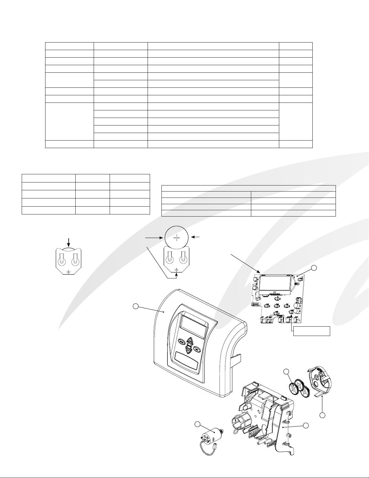
For Valve Type 1.0T, press and hold CLOCK and ▲for about 3 seconds to initiate an exchange of the tank in Service without
cycling the regeneration valve. After tank switch, days remaining and capacity remaining status is retained for each tank until the
next regeneration.
Prior to selecting the upow regeneration cycle, verify that the correct body, main piston, regenerant piston and stack are being
used, and that the injector plug(s) are in the correct location. Refer to the Service Manual for drawings and part numbers.
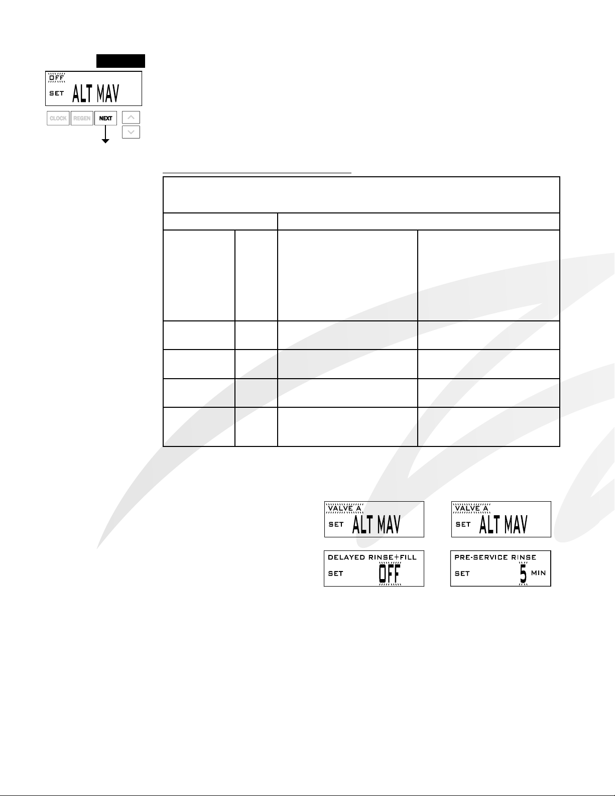
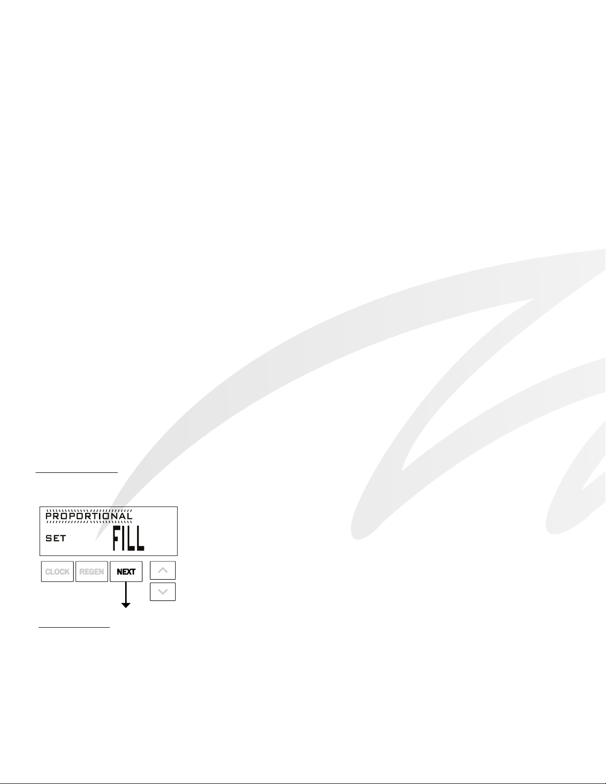
Proportional Brining
If the system is set up as a prell upow softener the control valve can also be set to normal or proportional brining.
This step will appear after Step 7S and before Step 8S if the system is set up as a prell
upow softener. The following options can be selected:
• NORMAL FILL - System always prells with the salt level selected.
• PROPORTIONAL FILL - If proportional brining is selected, the actual salt ll time will
be calculated by dividing the actual volume of treated water used by the full volumetric
capacity, then multiplying this value by the maximum salt ll time.
Press NEXT to go to the next step. Press REGEN to return to the previous step.
Backlight Control
As an energy-saving feature, the control will automatically turn off the display illumination after 5 minutes of inactivity. Any
further keypad activity will temporarily re-illuminate the display for 5 minutes. The Energy Saver feature default is ON.
The Master Illumination button is located in the lower right hand portion of the board. The purpose of the button is to manage
the keypad backlights and the Energy Saver feature. When the keypad backlights are OFF, pressing and holding this button for
about 5 seconds will turn the lights ON, and turn the energy-saver feature OFF, which will be indicated with a display “ENERGY
SAVER OFF”. If the button is not held until the Energy Saver Off display is shown, the backlights for the display and the
keypad will both go OFF after 5 minutes of no keypad activity. (The keypad backlights will remain OFF until either the Master
Illumination or any keypad button is pressed to turn them back ON.)

CK and EQ Manual Page 7
STEP 1CS
OEM Cycle Sequence
OEM Cycle Sequence instructions allows the OEM to set the order of
the cycle. The OEM Softener System Setup or the OEM Filter System
Setup allow the OEM to set how long cycles will last. The OEM may
choose up to 9 cycles in any order. END must be used as the last
cycle option. The SERVICE cycle should only be used in brine prell
applications.
The following is an example of how to set a valve so that when regeneration is initiated BACKWASH occurs rst, dn BRINE
occurs second, RINSE occurs third, and FILL occurs fourth.
Step 1CS – Press NEXT and ▼simultaneously for 3 seconds and release. Then press NEXT and ▼
simultaneously for 3 seconds and release. If screen in Step 2CS does not appear in 5 seconds the lock
on the valve is activated. To unlock press ▼, NEXT, ▲, and CLOCK in sequence, then press NEXT
and ▼ simultaneously for 3 seconds and release. Then press NEXT and ▼simultaneously for 3
seconds and release.
Step 2CS – Use ▲or ▼to select 1.0 for 1” valve, 1.25 for 1.25” valve, 1.5 for 1.5” valve, 2.0 for 2”
valve, or 1.0T for twin valve.
Press NEXT to go to Step 3CS. Press REGEN to return to exit OEM Cycle Sequence.
Step 3CS – When 2.0 is selected, an additional screen will appear. It is used to select which size ow
meter is to be used with the valve, 1.5, 2.0 or 3.0.
Press NEXT to go to Step 4CS.
Press REGEN to return to previous step.
STEP 2CS
Cycle Options
BACKWASH DN BRINE FILL
END
RINSE UP BRINE SOFTENING
OR FILTERING
STEP 3CS

Page 8 CK and EQ Manual
Step 4CS – Allows selection of one of the following using ▲or ▼ :
• the Control Valve to act as an alternator; or
• the Control Valve to have a no hard water bypass: or
• the Control Valve to have a Separate Source during the regeneration cycle; or
• the Control Valve to operate with the Clack System Controller.
Select OFF when none of these features are used.
Only use Clack No Hard Water Bypass Valves or Clack Motorized Alternating Valves (MAV) with these
selections. Clack No Hard Water Bypass Valves (1” or 1.25” V3070FF or V3070FM) are not designed
to be used with the alternator function or separate source mode.
Selecting the Control Valve to act as an alternator:
Prior to starting the programming steps, connect the communication cable to each control valve board’s
three pin connector labeled ‘COMM CABLE’. Also connect the meter cord to either control valve to the
three pin connector labeled ‘METER’.
Softener Valve Programming Steps
OEM Cycle
Sequence
Step
4CS
Set to VALVE A
Connect the outlet plumbing of
VALVE A to the MAV’s A port and
connect the MAV’s two pin wire
connector to the two pin connector
labeled “DRIVE” on VALVE A
Set to VALVE V
Connect the outlet plumbing of
VALVE B to the MAV’s B port. No
electrical connections are required
between the VALVE B and the
M AV.
OEM Softener
System Setup Step 7S Set System Capacity Set System Capacity
OEM Softener
System Setup Step 8S Set to ‘AUTO’ Set to ‘AUTO’
OEM Softener
System Setup Step 9S Set regeneration time option to
‘IMMEDIATE REGEN’.
Set regeneration time option to ‘
IMMEDIATE REGEN ’.
Installer
Display
Settings
Step 5I Set Day Override to “OFF” Set Day Override to “OFF”
STEP 4CS
If set up for a lter, in Step 7F set
Volume Capacity in m3; in Step 8F
select Regeneration Time Option
“Immediate”; and in Step 3I select Day
Override “oFF”.
For Clack Corporation alternator
systems using WS1, WS1.25 or WS1.5
valves there will be an option to delay
the last two cycles of regeneration
(only “Rinse” and “Fill”). This feature
splits the regeneration into two portions. The rst portion of the regeneration will start immediately and
all programmed cycles before the “Rinse” and “Fill” cycles will be performed. After all programmed
cycles before “Rinse” and “Fill” are completed the control valve will drive to the service position
(displaying “Delayed Rinse + Fill Pending”). When the volume of the on-line unit is depleted to
10% of its programmed capacity, the control valve will be triggered to nish the second portion of
the regeneration. Once “Rinse” and “Fill” are completed, the valve will re-enter Standby mode until
requested to come on-line for Service.
For Clack Corporation alternator systems using the WS2 valve, when NEXT is pressed after selecting
VALVE A or VALVE B, a display will allow the user to set the amount of pre-service rinse time for the
stand by tank just prior to returning to service.
WS1, WS1.25
and WS1.5 Valves
WS2
Valve

CK and EQ Manual Page 9
Conguring the Control Valve for Separate Source Operation:
Select Separate Source for control operation. For separate source operation, the three wire connector
is not used. Selection requires that a connection to a Clack Motorized Alternator Valve (MAV) is made
to the two pin connector labeled MAV MTR located on the printed circuit board. The C port of the
MAV must be connected to the valve inlet and the A port connected to the separate source used during
regeneration. The B port must be connected to the feed water supply.
When set to Separate Source the MAV will be driven closed before the rst regeneration cycle, and be
driven open after the last regeneration cycle.
NOTE: If the control valve enters into an error state during regeneration mode, the MAV will either
remain in Service or be returned to Service until the error is corrected and reset.
Conguring the Control Valve for No Hard Water Bypass Operation:
Select NO HARD BYPASS for control operation. For no hard water bypass operation the three wire
connector is not used. Selection requires that a connection to MAV or a Clack No Hard Water Bypass
Valve is made to the two pin connector labeled MAV MTR located on the printed circuit board. If using
a MAV, the A port of the MAV must be plugged and the valve outlet connected to the B port. When set
to No Hard Water Bypass the MAV will be driven closed before the rst regeneration cycle that is not
FILL or SOFTENING or FILTERING, and be driven open after the last regeneration cycle that is not
FILL.
NOTE: If the control valve enters into an error state during regeneration mode, the no hard water
bypass valve will either remain in Service or be returned to Service until the error is corrected and
reset.
Retracted
Valve “A” in Service Position =
MAV piston rod Retracted
Extended
Valve “B” in Service Position = MAV
piston rod Extended
Note: Clack Twin Alternator Operations
• Twin alternating systems can be programmed with a day override setting combined with the normal volume-based regeneration
programming. A twin alternating system in this conguration will then regenerate based on the volume used or the day override if there is
a period of low water usage.
• Twin alternating systems can be programmed as a time clock only based regenerating system. In this conguration, the days remaining are
counted only on the unit that is in service. The unit in Stand-by Mode only notes days in diagnostics, which results in time clock only twin
regeneration initiation.
• Twin alternating systems can be programmed for a delayed regeneration time. The system will allow an immediate transfer of the MAV
to switch tanks and place a fully regenerated unit in service once a unit becomes exhausted. The exhausted unit will then be placed into
Stand-by Mode and allowed to have a delayed regeneration at the pre-set time.
Conguring the Control Valve to operate with Clack System Controller:
Select SYSTEM CONTROLLER to link the Control Valve to the Clack System Controller. For
communication between the Control Valve and the System Controller, a three-wire communication
cable is required. Selection requires that a connection to a Clack No Hard Water Bypass (V3070FF
or V3070FM) be made to the two-pin connector labeled MAV located on the printed circuit board for
WS1and WS1.25 control valves. For valve types WS1.5 and WS2, a connection from a Clack No Hard
Water Bypass (V3097/BSPT or V3098/ BSPT) to the two pin connector labeled MAV located on the
printed circuit board is required.
Press NEXT to go to Step 5CS. Press REGEN to return to previous step.

Page 10 CK and EQ Manual
STEP 5CS Step 5CS – Set Auxiliary Drive Output (MAV only) to operate in one of three modes:
• Set TIME: Allows Auxiliary MAV to switch positions at a set time in relation to the start of
regeneration for a preset duration, independently of the actual regeneration status.
• Set SEPARATE SOURCE: Allows Auxiliary MAV to switch positions before the start of
regeneration and then switch back at the end of regeneration.
• Set OFF: Deactivates this output.
Only use Clack Motorized Alternating Valves (MAV) with these selections. Clack No Hard Water
Bypass Valves (1” or 1.25” V3070FF or V3070FM) are not designed to be used with the “TIME” or
“SEPARATE SOURCE” modes.
Press NEXT to go to Step 6CS. Press REGEN to return to previous step.
Displays if TIME
is selected
Displays if SEPARATE SOURCE
is selected

CK and EQ Manual Page 11
Step 6CS – This allows the use of an outside signal to control the initiation of a regeneration.
Selection only matters if a connection is made to the two pin connector labeled DP SWITCH
located on the printed circuit board. Following is an explanation of the options:
oFF – Feature not used.
NOTE: In a twin alternating system each control must have a separate dP signal or dP
switch. One dP signal or one dP switch cannot be used for both controls. For Alternator
Systems only - the DP input is ignored on units while they are in Regeneration or
Standby.
IMMED REG – If the dP switch is closed for an accumulative time of 2 minutes a regeneration
will be signaled to the unit. In a twin alternating system the MAV will transition rst to switch
units so that the signaled unit can start regeneration. After the MAV is fully transitioned the
regeneration begins immediately. Note: For WS1 – WS1.5 control valves programmed for twin
alternating: if the dP function “IMMED REG” is set, the Delayed Rinse and Fill feature is not
available.
DELAY REG – If the dP switch is closed for an accumulative time of 2 minutes a regeneration
will occur at the scheduled delayed regeneration time. In a twin alternating system once the dP
switch is triggered the PC Board will display “REGEN TODAY” and when the delayed regen
time comes the control will switch tanks and the triggered unit will then go into regeneration.
Note: For WS1 – WS1.5 control valves programmed for twin alternating: if the dP function
“DELAY REG” is set, the Delayed Rinse and Fill feature is not available.
HOLD REG – If the dP switch is closed a regeneration will be prevented from occurring while
there is switch closure. In a twin alternating system the regeneration of a unit can be prevented
upon switch closure. If the unit depletes the capacity down to zero it will not be allowed to
switch tanks to regenerate until the switch is open. Note: For WS1 – WS1.5 control valves
programmed for twin alternating the Delayed Rinse and Fill feature can be set in conjunction
with the “HOLD REG” if desired.
Press NEXT to go to Step 7CS. Press REGEN to return to previous step.
STEP 6CS
Step 7CS – Determine the measurement to calculate volumetric capacity. The
choices are:
PPM parts per million
FH French degrees
dH German degrees
Press NEXT to go to Step 8CS. Press REGEN to return to previous step.
STEP 7CS

Page 12 CK and EQ Manual
STEP 10CS
STEP 11CS
Step 10CS - Press ▲or ▼until RINSE appears. Press NEXT to go to Step 11CS. Press REGEN to
return to previous step.
Step 11CS - Press ▲or ▼until FILL appears. Press NEXT to go to Step 12CS. Press REGEN to return
to previous step.
Step 12CS - Press ▲or ▼until END appears. Press NEXT to exit OEM Cycle Sequence. Press
REGEN to return to previous step.
RETURN TO NORMAL MODE
STEP 12CS
STEP 9CS Step 9CS - Press ▲or ▼ until Regenerant Draw DN appears. Prior to selecting the upow regeneration
cycle, verify that the correct body, main piston, regenerant piston and stack are being used, and that the
injector plug(s) are in the correct location. Refer to the Service Manual for drawings and part numbers.
Press NEXT to go to Step 10CS. Press REGEN to return to previous step.
Step 8CS – Press ▲or ▼until BACKWASH appears. Press NEXT to go to Step 9CS. Press REGEN
to return to previous step.
STEP 8CS
Fill Units: if Step 2CS is set to 1.5, and FILL is part of the Regeneration Cycle Sequence,
FILL UNITS of MIN or kg can be selected.
Last Step of OEM Cycle Sequence

CK and EQ Manual Page 13
OEM Softener System Setup
In OEM Softener System Setup the OEM chooses the time for the cycles selected in OEM Cycle Sequence and species other
operating parameters for the system. The upper and lower limits of the allowable values for the cycles are as follows:
If an upow control valve is programmed for prell the proportional brining display will appear after the system capacity display
(Step 7S).
Cycle Options Units Lower/Upper Limit
Backwash Minutes 1 to 120
Rinse (fast) Minutes 1 to 120
Regenerant DRAW DN (combination of brining and slow rinse) Minutes 1 to 180
Regenerant DRAW UP (combination of brining and slow rinse) Minutes 1 to 180
Fill for all valves except WS2 Kg 0.05 to 100
Fill for WS2 valves or WS1.5 set to “MIN” Minutes 0.1 to 99
Service Minutes 1 to 480
STEP 1S
Step 1S – Press NEXT and ▼simultaneously for 3 seconds and release. If screen in Step 2S does not
appear in 5 seconds the lock on the valve is activated. To unlock press ▼, NEXT, ▲, and CLOCK in
sequence, then press NEXT and ▼simultaneously for 3 seconds and release.
STEP 2S
Step 2S – Choose SOFTENING using ▲or ▼. Press NEXT to go to Step 3S. Press REGEN to exit
OEM Softener System Setup.
STEP 3S
Step 3S – Select the time for the rst cycle (which in this example is BACKWASH) using ▲or ▼.
Press NEXT to go to Step 4S. Press REGEN to return to previous step.
STEP 4S
Step 4S – Select the time for the second cycle (which in this example is DRAW) using ▲or ▼. Press
NEXT to go to Step 5S. Press REGEN to return to previous step.
STEP 5S
Step 5S – Select the time for the third cycle (which in this example is RINSE) using ▲or ▼. Press
NEXT to go to Step 6S. Press REGEN to return to previous step.
Since no time is associated with the END cycle, the END cycle will not appear in the OEM Softener System Setup sequence.

Page 14 CK and EQ Manual
STEP 6S Step 6S – Select the kg for the fourth cycle (which in this example is FILL) using ▲or ▼. When 2.0
is selected in Step 2CS, FILL is in minutes. If 1.5 is selected in Step 2CS, setting the last step of the
OEM Cycle Sequence determines if the value here is kg or minutes. Press NEXT to go to Step 7S. Press
REGEN to return to previous step.
STEP 7S Step 7S –Set System Capacity using▲or ▼. See chart. The System Capacity setting should be based on the
volume of resin and kg of salt ll set in Step 6S. The system capacity
and hardness levels entered are used to determine the Volume Capacity.
Press NEXT to go to Step 8S. Press REGEN to return to previous step.
STEP 8S Step 8S – Set Regeneration Trigger using ▲or ▼. If value is set to:
• “AUTO” capacity will be automatically calculated and reserve capacity will be automatically estimated;
• “OFF” regeneration will be based solely on the day override set (see Installer Display Settings Step 3I); or
• a number, regeneration initiation will be based off the value specied.
If “OFF” or a number is used, hardness display will not be allowed to be set in Installer Display Settings Step 2I.
If “OFF” is selected, Regeneration Time is automatically “Delayed”, so Step 9S will not appear.
See Setting Options Table for more detail. Press NEXT to go to Step 9S. Press REGEN to return to previous step.
STEP 9S Step 9S – Set Regeneration Time Options using ▲or ▼. If value is set to:
• “DELAYED REGEN” means regeneration will occur at the preset time;
• “IMMEDIATE REGEN” means regeneration will occur immediately when the volume capacity reaches 0 (zero);
or
• “BOTH” means regeneration will occur at one of the following:
— the preset time when the volume capacity falls below the reserve or the specied number of days between
regenerations is reached whichever comes rst; or
— immediately after 10 minutes of no water usage when the volume capacity reaches 0 (zero).
“DELAYED REGEN” is the default if Step 4CS is set to VALVE A or VALVE B, and “BOTH” will not be
available.
“IMMEDIATE REGEN” is the default if Step 2SC is set to 1.0T, and “BOTH” is not available.
This step will not appear if Step 8S is set to OFF or Step 4CS is set to “SYSTEM CONTROLLER”.
See Setting Options Table for more detail. Press NEXT to go to Step 10S. Press REGEN to return to previous step.
Step 10S: Set Relay 1 operation using ▲or ▼. The choices are:
• Set REGEN TIME: Relay activates after a set time at the beginning of a regeneration and then deactivates after
a set period of time. The start of regeneration is dened as the rst backwash cycle or Regenerant Draw UP (1”
only) or DN, which ever comes rst.
• Set VOLUME: Relay activates after a set number of liters have been used while in service and then deactivates
after a set period of time or after the meter stops registering ow, whichever comes rst.
• Set REGEN VOLUME: Relay activates after a set number of liters have been used while in service or during
regeneration and then deactivates after a set period of time or after the meter stops registering ow, whichever
comes rst.
• Set OFF: If set to Off, Steps 11S and 12S will not be shown.
Press NEXT to go to Step 11S. Press REGEN to return to previous step.
STEP 10S
Setting Units Limits Default
PPM kg 0.10-200 1.50
°fH m³ 1-6000 160 m³
°dH m³ 1-6000 80 m³

CK and EQ Manual Page 15
STEP 11S
Step 11S: Set Relay 1 SETPOINT Time or Volume using ▲or ▼. The choices are:
• Relay Actuation Time: After the start of a regeneration the amount of time that should pass prior to activating
the relay. The start of regeneration is dened as the rst backwash cycle or Regenerant Draw UP (1” only) or DN,
which ever comes rst. Ranges from 0 to 500 minutes.
• Relay Actuation Volume: Relay activates after a set number of liters have passed. Ranges from 1 to 200 liters.
Press NEXT to go to Step 12S. Press REGEN to return to previous step.
STEP 12S
Step 12S: Set Relay DURATION TIME using ▲or ▼.
• If TIME is selected in Step 10S, the relay will deactivate after the time set has expired. Ranges from 0:01 to
500:00 minutes.
• If Volume or REGEN Volume is selected in Step 10S, the relay will deactivate after the time set has expired.
Press NEXT to go to Step 13S. Press REGEN to return to previous step.
Step 13S: Set Relay 2 operation using ▲or ▼. The choices are the same as Step 10S, with the addition of
Error Monitor. When Error Monitor is selected, Relay 2 closes whenever the valve enters the Error Mode, and
immediately deactivates when Error Mode is exited.
• If set to Off, Steps 14S and 15S will not be shown.
Press NEXT to go to Step 14S. Press REGEN to return to previous step.
STEP 13S
STEP 14S
Step 14S: Set Relay 2 SETPOINT Time or Volume using ▲or ▼. The choices are the same as Step 11S.
Press NEXT to go to Step 15S. Press REGEN to return to previous step.
STEP 15S
Step 15S: Set Relay DURATION TIME using ▲or ▼.
• If TIME is selected in Step 13S the relay will deactivate after the time set has expired.
• If Volume or REGEN Volume is selected in Step 13S the relay will deactivate after the time set has expired or
after the meter stops registering ow, whichever comes rst.
Press NEXT to go to Step 16S. Press REGEN to return to previous step.
Step 16S: Set Service Alarm using ▲or ▼. The choices are Time, m³, BOTH or OFF. Selecting OFF disables
this feature. If OFF is selected press NEXT to exit OEM System Setup. If TIME, m³ or BOTH is selected press
NEXT to select the TIME and/or m³ values. Press REGEN to return to previous step.
STEP 16S
RETURN TO NORMAL MODE

Page 16 CK and EQ Manual
Setting Options Table
Filters should only use shaded options.
Volume
Capacity
Regeneration
Time Option
Day
Override Result3
AUTO DELAYED
REGEN OFF
Reserve capacity automatically estimated.
Regeneration occurs when volume capacity falls below the reserve
capacity at the next Regen Set Time
AUTO DELAYED
REGEN
Any
number
Reserve capacity automatically estimated.
Regeneration occurs at the next Regen Set Time when volume capacity
falls below the reserve capacity or the specied number of days between
regenerations is reached.
Any
number
DELAYED
REGEN OFF
Reserve capacity not automatically estimated.
Regeneration occurs at the next Regen Set Time when volume
capacity reaches 0.
OFF DELAYED
REGEN
Any
number
Reserve capacity not automatically estimated.
Regeneration occurs at the next Regen Set Time when the specied
number of days between regenerations is reached.
Any
number
DELAYED
REGEN
Any
number
Reserve capacity not automatically estimated.
Regeneration occurs at the next Regen Set Time when volume
capacity reaches 0 or the specied number of days between
regenerations is reached.
AUTO IMMEDIATE
REGEN OFF
Reserve capacity not automatically estimated.
Regeneration occurs immediately when volume capacity reaches 0.
Time of regeneration will not be allowed to be set because regeneration
will always occur when volume capacity reaches 0.
Any
number
IMMEDIATE
REGEN OFF
Reserve capacity not automatically estimated.
Regeneration occurs immediately when volume capacity reaches 0.
Time of regeneration will not be allowed to be set because regeneration
will always occur when volume capacity reaches 0.
AUTO BOTH OFF
Reserve capacity automatically estimated.
Regeneration occurs when volume capacity falls below the reserve
capacity at the next Regen Set Time or regeneration occurs after 10
minutes of no water usage when volume capacity reaches 0.
AUTO BOTH Any
number
Reserve capacity automatically estimated.
Regeneration occurs at the next Regen Set Time when volume capacity
falls below the reserve capacity or the specied number of days between
regenerations is reached or regeneration occurs after 10 minutes of no
water usage when volume capacity reaches 0.
Any
number BOTH Any
number
Reserve capacity not automatically estimated.
Regeneration occurs at the next Regen Set Time when the specied
number of days between regenerations is reached or regeneration occurs
after 10 minutes of no water usage when volume capacity reaches 0.
3Reserve Capacity estimate is based on history of water usage. Reserve Capacity estimate is not available with
alternator systems or Twin Tank Valve.

CK and EQ Manual Page 17
OEM Filter System Setup
In OEM Filter System Setup the OEM chooses the time for the cycles selected in OEM Cycle Sequence and species other
operating parameters for the system. The upper and lower limits of the allowable values for the cycles are as follows:
Since no time is associated with the END cycle, the END cycle will not appear in the OEM Filter System Setup sequence.
STEP 1F
STEP 2F
STEP 3F
STEP 4F
STEP 5F
Step 1F – Press NEXT and ▼simultaneously for 3 seconds and release. If screen in Step 2F does not
appear in 5 seconds the lock on the valve is activated. To unlock press ▼, NEXT, ▲, and CLOCK in
sequence, then press NEXT and ▼simultaneously for 3 seconds and release.
Step 2F – Choose FILTERING using ▼or ▲. Press NEXT to go to Step 3F. Press REGEN to exit
OEM Filter System Setup.
Step 3F – Select the time for the rst cycle (which in this example is BACKWASH) using ▼or ▲.
Press NEXT to go to Step 4F. Press REGEN to return to previous step.
Step 4F – Select the time for the second cycle (which in this example is DRAW) using ▼or ▲. Press
NEXT to go to Step 5F. Press REGEN to return to previous step.
Step 5F – Select the time for the third cycle (which in this example is RINSE) using ▼or ▲. Press
NEXT to go to Step 6F. Press REGEN to return to previous step.
Cycle Options Units Lower/Upper Limit
Backwash Minutes 1 to 120
Rinse (fast) Minutes 1 to 120
Regenerant Draw DN (combination of regenerant and slow rinse) Minutes 1 to 180
Fill for all valves except WS2 Liters 0.2 to 76.00
Fill for WS2 valves Minutes 0.1 to 99
Service Minutes 1 to 480

Page 18 CK and EQ Manual
STEP 6F Step 6F – Select the liters for the fourth cycle (which in this example is FILL) using ▼or ▲. When
2.0 is selected in Step 2CS, FILL is in minutes. Press NEXT to go to Step 7F. Press REGEN to return
to previous step.
Step 7F – Set Regeneration Trigger using ▲or ▼. If value is set to:
• “OFF” regeneration will be based solely on the day override set (see Installer Display/Settings
Step 3I); or
• a number, regeneration initiation will be based off the value specied.
See Setting Options Table for more detail. Press REGEN to return to previous step.
STEP 7F
Step 8F – Set Regeneration Time Options using ▲or ▼. If “OFF” was selected in Step 7F, this screen
will not appear.
If value is set to:
• “DELAYED REGEN” means regeneration will occur at the preset time;
• “IMMEDIATE” means regeneration will occur immediately when the volume capacity reaches 0
(zero); or
• “BOTH” means regeneration will occur at one of the following:
-the preset time when the volume capacity falls below the reserve or the specied number of days
between regenerations is reached whichever comes rst; or
-immediately after 10 minutes of no water usage when the volume capacity reaches 0 (zero).
“DELAYED REGEN is the default if Step 4CS is set to VALVE A or VALVE B, and “BOTH” will not
be available.
“IMMEDIATE REGEN” is the default if Step 2SC is set to 1.0T, and “BOTH” is not available.
This step will not appear if Step 7F is set to OFF or Step 4CS is set to “SYSTEM CONTROLLER”.
See Setting Options Table for more detail. Press NEXT to go to Step 9F.
STEP 8F
Step 9F – Set Relay 1 operation using ▲or ▼. The choices are:
• Set REGEN TIME: Relay activates after a set time at the beginning of a regeneration and then
deactivates after a set period of time. The start of regeneration is dened as the rst backwash cycle or
Regenerant Draw UP (1” only) or DN, whichever comes rst.
• Set VOLUME: Relay activates after a set number of liters have been used while in service and then
deactivates after a set period of time or after the meter stops registering ow, whichever comes rst.
• Set REGEN VOLUME: Relay activates after a set number of liters have been used while in
service or during regeneration and then deactivates after a set period of time or after the meter stops
registering ow, whichever comes rst.
• Set OFF: If set to Off, Steps 10F and 11F will not be shown.
Press NEXT to go to Step 10F. Press REGEN to return to previous step.
STEP 9F

CK and EQ Manual Page 19
Step 10F – Set Relay 1 SETPOINT Time or Volume using ▲or ▼. The choices are:
• Relay Actuation Time: After the start of a regeneration the amount of time that should pass prior
to activating the relay. The start of regeneration is dened as the rst backwash cycle or Regenerant
Draw UP (1” only) or DN, whichever comes rst. Ranges from 0 to 500 minutes.
• Relay Actuation Volume: Relay activates after a set number of liters have passed. Ranges from 1 to
200 liters.
Press NEXT to go to Step 11F. Press REGEN to return to previous step.
STEP 10F
Step 11F: Set Relay DURATION TIME using ▲or ▼.
• If TIME is selected in Step 9F, the relay will deactivate after the time set has expired. Ranges from
0:01 to 500:00 minutes.
• If Volume or REGEN Volume is selected in Step 9F, the relay will deactivate after the time set has
expired.
Press NEXT to go to Step 12F. Press REGEN to return to previous step.
STEP 11F
STEP 12F Step 12F: Set Relay 2 operation using ▲or ▼. Set Relay 1 operation using ▲or ▼. The choices are:
• Set REGEN TIME: Relay activates after a set time at the beginning of a regeneration and then
deactivates after a set period of time. The start of regeneration is dened as the rst backwash cycle or
Regenerant Draw UP (1” only) or DN, whichever comes rst.
• Set VOLUME: Relay activates after a set number of liters have been used while in service and then
deactivates after a set period of time or after the meter stops registering ow, whichever comes rst.
• Set REGEN VOLUME: Relay activates after a set number of liters have been used while in
service or during regeneration and then deactivates after a set period of time or after the meter stops
registering ow, whichever comes rst.
• ERROR MONITOR: When Error Monitor is selected, Relay 2 closes whenever the valve enters the
Error Mode, and immediately deactivates when Error Mode is exited.
• If set to OFF or ERROR MONITOR, Steps 13F and 14F will not be shown.
Press NEXT to go to Step 13F. Press REGEN to return to previous step.
STEP 13F Step 13F: Set Relay 2 SETPOINT Time or Volume using ▲or ▼. The choices are the same as Step
10F.
Press NEXT to go to Step 14F. Press REGEN to return to previous step.
STEP 14F Step 14F: Set Relay DURATION TIME using ▲or ▼.
• If TIME is selected in Step 12F the relay will deactivate after the time set has expired.
• If Volume or REGEN Volume is selected in Step 12F the relay will deactivate after the time set has
expired or after the meter stops registering ow, whichever comes rst.
Press NEXT to go to Step 15F. Press REGEN to return to previous step.
STEP 15F Step 15F: Set Service Alarm using ▲or ▼. The choices are Time, m³, BOTH or OFF. Selecting OFF
disables this feature. If OFF is selected press NEXT to exit OEM System Setup. If TIME, m³ or BOTH
is selected press NEXT to select the TIME and/or m³ values. Press REGEN to return to previous step.
RETURN TO NORMAL MODE

Page 20 CK and EQ Manual
Installer Display Settings
STEP 1I
STEP 1I - Press NEXT and ▲simultaneously for 3 seconds.
STEP 3I
STEP 3I – Hardness: Set the amount of inuent hardness
using ▼or ▲. See Table. This display will not appear if
“FILTERING” is selected in Step 2F OR if “OFF” or a
number was selected in Step 8S. Press NEXT to go to step
4I. Press REGEN to exit Installer Display Settings.
STEP 5I STEP 5I – Day Override: When volume capacity is set to “OFF”, sets the number of days between
regenerations. When volume capacity is set to AUTO or to a number, sets the maximum number of
days between regenerations. If value set to “OFF”, regeneration initiation is based solely on volume
used. If value is set as a number (allowable range from 1 to 28) a regeneration initiation will be
called for on that day even if sufcient volume of water were not used to call for a regeneration. Set
Day Override using ▼or ▲:
• number of days between regeneration (1 to 28); or
• “OFF”.
See Setting Options Table for more detail on setup. Press NEXT to go to step 6I. Press REGEN to
return to previous step.
STEP 6I
STEP 6I – Next Regeneration Time (hour): Set the hour of day for regeneration using ▼or ▲. The
default time is 2:00. This display will show not to be viewed if “IMMEDIATE” is selected in Set
Regeneration Time Option in OEM Softener System Setup Step 9S or OEM Filter System Setup Step
8F. Press NEXT to go to step 7I. Press REGEN to return to previous step.
STEP 7I
STEP 7I – Next Regeneration Time (minutes): Set the minutes of day for regeneration using ▼or
▲. This display will not be shown if “IMMEDIATE” is selected in Set Regeneration Time Option
in OEM Softener System Setup Step 9S or OEM Filter System Setup Step 8F. Press NEXT to exit
Installer Display Settings. Press REGEN to return to previous step.
RETURN TO NORMAL MODE
STEP 2I
STEP 2I – Set Display Language. Select between English, German, French or Spanish.
Press NEXT to go to Step 3I. Press REGEN to exit Installer Display Settings.
STEP 4I
STEP 4I – Service Water Hardness. Setting range is always less than the setting in Step 3I. This
screen will not be displayed when valve is set as a Filter, or if “Auto” is not selected in step 8S.
Press NEXT to go to Step 5I. Press REGEN to return to previous step.
Setting Limits Default
PPM 1-2500 340
°fH 1-250 34
°dH 1-150 18
This manual suits for next models
1
Table of contents
Other Water Specialist Control Unit manuals

Water Specialist
Water Specialist WS1CT User manual

Water Specialist
Water Specialist WS1HR User manual

Water Specialist
Water Specialist WS1TT User manual

Water Specialist
Water Specialist EE User manual

Water Specialist
Water Specialist WS1TC Guide

Water Specialist
Water Specialist WS2HF User manual

Water Specialist
Water Specialist WS2H User manual

Water Specialist
Water Specialist WS1CC Guide