Water Specialist EE User manual
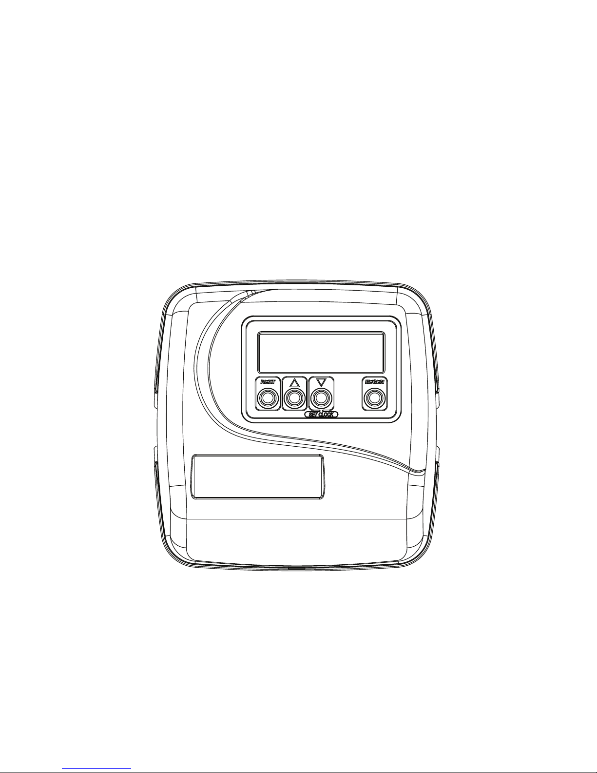
Water Specialist EE
Control Valve
Programming and Cover Drawing Manual

Page 2 EE Manual

EE Manual Page 3
Table of Contents
EE Front Cover and Drive Assembly.................................................................................................................................. 4
Regeneration and Error Screens, Button Operations and Functions................................................................................... 5
User Displays...................................................................................................................................................................... 6
Configuration Settings ........................................................................................................................................................ 7
OEM Softener System Setup ............................................................................................................................................ 11
Setting Options Table........................................................................................................................................................ 14
OEM Filter System Setup ................................................................................................................................................. 15
Installer Display Settings - Regeneration Type Auto........................................................................................................ 17
Installer Display Settings - 28 Day Regeneration............................................................................................................. 18
Installer Display Settings - 7 Day Regeneration............................................................................................................... 19
Diagnostics........................................................................................................................................................................ 20
Page 4 EE Manual
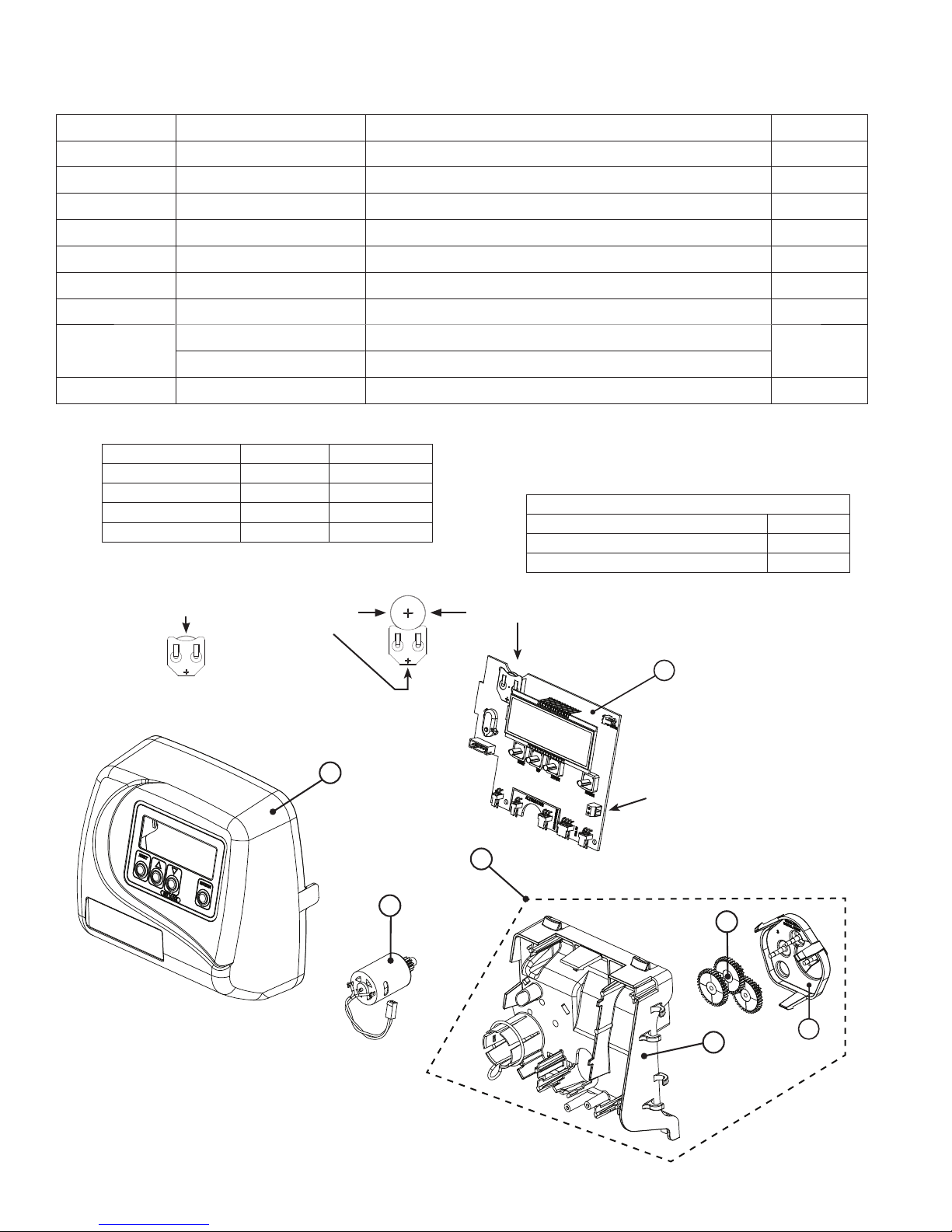
Drawing No. Order No. Description Quantity
1 V3175EE-01 WS1EE FRONT COVER ASSEMBLY 1
2 V3107-01 WS1 MOTOR 1
3 V3002-A WS1 DRIVE BRACKET ASY 1
4 V3408EE-04BOARD WS1THRU/2 EE PCB 5 DIGIT REPL 1
5 V3110 WS1 DRIVE GEAR 12X36 3
6 V3109 WS1 DRIVE GEAR COVER 1
7 V3106-01 WS1 DRIVE BRACKET & SPRING CLIP 1
Not Shown V3186-05 WS1 POWER SUPPLY US 15VDC VI 1
V3186-01 WS1 POWER CORD ONLY
Not Shown V3178 WS1 DRIVE BACK PLATE 1
EE Front Cover and Drive Assembly
4
AC Adapter U.S. International
Supply Voltage 120 V AC 230V AC
Supply Frequency 60 Hz 50 Hz
Output Voltage 15VDC 15VDC
Output Current 500 mA 500 mA
Refer to Control Valve Service Manual for other drawings and part numbers.
Relay Specifications: 12V DC Relay with a coil resistance
not less than 80 ohms. If mounting relay under the cover
check for proper mounting dimensions on the backplate.
Wiring for Correct On/Off Operation
PC Board Relay Terminal Block Relay
RLY 1 Coil -
+ COM Coil +
Battery replacement is 3 volt
lithium coin cell type 2032.
Correct
Battery
Orientation
Battery Fully Seated
When replacing the battery, align
positives and push down to fully seat.
PC Board Relay
Terminal Block
1
2
5
6
7
3

EE Manual Page 5
Range
Cycle Softening Filtering Regen Filtering
Backwash
Backwash
Regenerant Draw/Slow Rinse (UP or DN)
Fast Rinse
Regenerant Refill
Regenerant Refill 2.0 or 1.5 set to MIN (softening only)
Service
1-120 minutes
1-180 minutes
1-120 minutes
0.1-200.0 lbs.
0.1-99.0 minutes
1-480 minutes
1-120 minutes
1-180 minutes
1-120 minutes
1-99.0 GAL
0.1-99.0 minutes
NA
1-120 min.
NA
1-120 min.
NA
NA
NA
Regeneration and Error Screens
The user can initiate manual regeneration. The user has the option to request the manual regeneration at the delayed regeneration
time or to have the regeneration occur immediately:
1. Pressing and releasing the REGEN button. “ REGEN TODAY” will flash on the display and the regeneration will occur at the
delayed regeneration time. The user can cancel the request by pressing and releasing the REGEN button.
2. Pressing and holding the REGEN button for approximately 3 seconds will immediately start the regeneration. The user cannot
cancel this request, except by resetting the control by pressing NEXT and REGEN simultaneously for 3 seconds.
Regeneration Cycles and Times
Button Operation and Function
Changes variable being displayed.
Pressing once and releasing will schedule a regeneration at the preset delayed regeneration time.
Pressing again and releasing will cancel the regeneration.
Pressing and holding for 3 seconds will initiate an immediate regeneration
Pressing while in regeneration will advance to the next cycle.
Pressing in the program levels will go backwards to the previous screen
Key sequence to lock and unlock program settings.
Scrolls to the next display.
Holding for 3 seconds initiates a control reset. The software version is displayed and the piston returns
to the home/service position, resynchronizing the valve.
Used with valve type 1.0 , holding for at least 3 seconds causes a switch in the tank in Service without cycling
the regeneration valve. After tank switch, days remaining and capacity remaining status is retained for each
tank until the next regeneration.
Regen Screen
Displays the time remaining in the current cycle. Pressing REGEN advances to the next cycle.
Error Screen
Alternated flashing Err and error code every 3 seconds. Clear by disconnecting
the power supply at the PC board and reconnecting, or press NEXT and
REGEN simultaneously for 3 seconds.
In Alternator Systems when a unit is waiting to initiate the first cycle step of regeneration,
“REGEN Pndg” is displayed.
“REGEN Pndg RINSE FILL” is displayed whenever a zero-capacity tank has transferred to
an off-line state and is currently waiting to initiate the second portion of a regeneration cycle.
Viewed only when Delayed Rinse and Fill is set to ON.
“STbY” is displayed in Alternator Systems when a valve is in Standby state.
If 1.5 or 2.0 is selected in Step 2CS, cycles can be set to “oFF”.

Page 6 EE Manual
User 3
Flow Rate.
Displays present flow rate.
Not viewed (along with SOFTENING or FILTERING Icon) if ALT A or ALT b is set
in CONFIGURATION 4 and the valve is currently in Standby. When 1.0 is set in
CONFIGURATION 1, the display will indicate the tank currently in Service (“A” or “b”) in
the leftmost digit.
User 1
Typical user display. Shows volume remaining to regeneration. This screen will not be
viewed if the control is set for time-clock operation.
User 2
Displays number of days to next regeneration.
User 4
Displays total volume in gallons since last reset. If a meter is not used this display will be
shown but 0 will be displayed.
PRESS ▼FOR 3 SECONDS TO RESET TO 0.
User 5
Shows current time.
Setting Time of Day
Push NEXT until time of day screen is displayed. Press and hold ▼until SET TIME is
displayed and the hour flashes once. Press ▲or ▼until the correct hour is displayed.
Then press NEXT. The minutes will flash. Press ▲or ▼until the correct minute is displayed.
Press NEXT to return to the User Displays. Time of day should only need to be set after
power outages lasting more than 8 hours, if the battery has been depleted and a power outage
occurs, or when daylight saving time begins or ends. If a power outage lasting more than 8
hours occurs, the time of day will flash on and off which indicates the time of day should be
reset. If a power outage lasts less than 8 hours and the time of day flashes on and off, the time
of day should be reset and the battery replaced.
User Displays
General Operation When the system is operating, one of five displays may be shown. Pressing NEXT will
alternate between the displays shown below.
EE Manual Page 7
Configuration Settings
Step 1CS – Press NEXT and ▼simultaneously for 5 seconds and release. Press NEXT and ▼
simultaneously for 5 seconds and release. If the screen in Step 2CS does not appear, the lock on the valve is
activated. To unlock, press ▼, NEXT, ▲and REGEN in sequence, then press NEXT and ▼simultaneously
for 5 seconds and release. Press NEXT and ▼simultaneously for 5 seconds and release.
Step 1CS
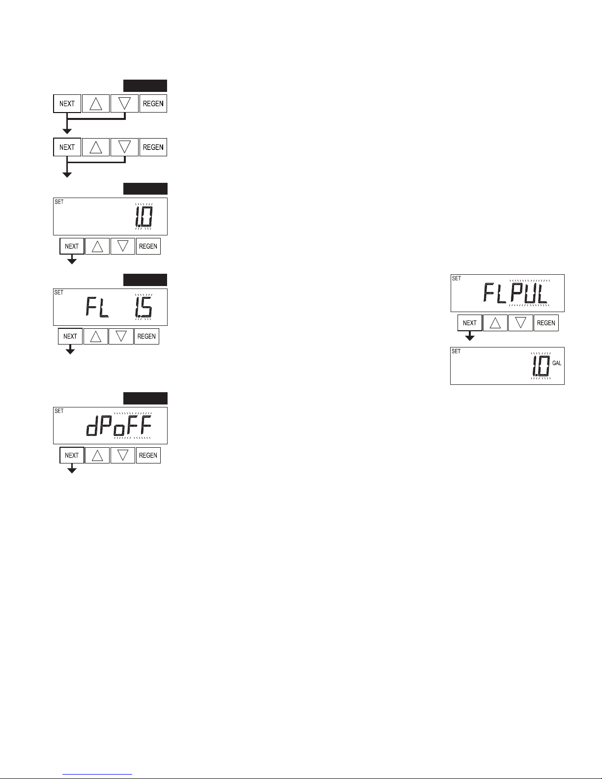
Step 2CS – Use ▲or ▼to select 1.0 for 1” valve, 1.25 for 1.25” valve, 1.5 for 1.5” valve, 2.0 for 2” valve
or 1.0T for twin valve. Press NEXT to go to Step 3CS. Press REGEN to exit Configuration Settings.
Step 2CS
Step 3CS – If 1.5 or 2.0 is selected in Step 2CS, an additional screen will
appear. It is used to select which size flow meter is to be used with the
valve, 1.0r, 1.5, 2.0 or 3.0. Variable meter pulses of 0.1-150.0 PPG can
also be selected. Press NEXT to go to Step 4CS. Press REGEN to return
to the previous step.
Step 3CS
Step 4CS Step 4CS – Selecting the use of an outside signal to initiate a regeneration: Selection only matters if a
connection is made to the two pin connector labeled DP SWITCH located on the printed circuit board.
Following is an explanation of the options:
oFF - feature not used
NOTE: In a twin alternating system each control must have a separate dP signal or dP switch. One dP signal
or one dP switch cannot be used for both controls.
on0 – If the dP switch is closed for an accumulative time of 2 minutes a regeneration will be signaled to the
unit. In a twin alternating system the MAV will transition first to switch units so that the signaled unit can
start regeneration. After the MAV has fully transitioned, the regeneration begins immediately. Note: For
WS1 – WS1.5 control valves programmed for twin alternating: if the dP function “on0” is set, the Delayed
Rinse and Fill feature is not available.
dEL – If the dP switch is closed for an accumulative time of 2 minutes a regeneration will occur at the
scheduled delayed regeneration time. In a twin alternating system once the dP switch is triggered the
PC Board will display “REGEN TODAY” and when the delayed regen time comes the control will
switch tanks and the triggered unit will then go into regeneration. Note: For WS1 – WS1.5 control valves
programmed for twin alternating: if the dP function “dEL” is set, the Delayed Rinse and Fill feature is not
available.
HoLd – If the dP switch is closed a regeneration will be prevented from occurring while there is switch
closure. In a twin alternating system the regeneration of a unit can be prevented upon switch closure. If the
unit depletes the capacity down to zero, it will not be allowed to switch tanks to regenerate until the switch
is open. Note: For WS1 – WS1.5 control valves programmed for twin alternating the Delayed Rinse and
Fill feature can be set.
Press NEXT to go to Step 5CS. Press REGEN to return to previous step.

Page 8 EE Manual
Step 5CS – This display will not appear if 1.0T was selected in Step
2CS. Allows selection of one of the following using ▲or ▼:
• the Control Valve to have no hard water bypass;
• the Control Valve to act as an alternator;
• the Control Valve to have a separate source during the regeneration
cycle; or
• the Control Valve to operate with the System Controller.
Select OFF when none of these features are used.
Only use Clack No Hard Water Bypass Valves or Clack Motorized Alternating Valves (MAV) with these selections. Clack No Hard Water
Bypass Valves (1” or 1.25” V3070FF or V3070FM) are not designed to be used with the alternator or separate source functions.
Step 5CS
Selecting the Control Valve to act as an alternator:
519.0 and higher = Use 3-wire Interconnect Cables for all communication between units.
518.3 and lower = Use 2-wire Interconnect Cables for twin alternators with independent flow meters.
Configuring the Control Valve for No Hard Water Bypass Operation:
Select nHbP for control operation. For no hard water bypass operation the three wire communication cable
is not used.
Selection requires that a connection to MAV or a Clack No Hard Water Bypass Valve is made to the two
pin connector labeled MAV located on the printed circuit board. If using a MAV, the A port of the MAV
must be plugged and the valve outlet connected to the B port. When set to nHbP the MAV will be driven
closed before the first regeneration cycle that is not FILL or SOFTENING or FILTERING, and be driven
open after the last regeneration cycle that is not FILL.
NOTE: If the control valve enters into an error state during regeneration mode, the no hard water bypass
valve will return to the open Position, if not already there.
Configuring the Control Valve for Separate Source Operation:
Select SEPS for control operation. For separate source operation the three wire communication cable is not
used.
Selection requires that a connection to a Clack Motorized Alternator Valve (MAV) is made to the two pin
connector labeled MAV located on the printed circuit board. The C port of the MAV must be connected to
the valve inlet and the A port connected to the separate source used during regeneration. The B port must
be connected to the feed water supply.
When set to SEPS the MAV will be driven closed before the first regeneration cycle, and be driven open
after the last regeneration cycle.
NOTE: If the control valve enters into an error state during regeneration mode, the MAV will return to the
open position, if not already there.
NOTE: If the control valve is in an error state during regeneration mode the MAV will close the B port and keep open the A port until the error is
corrected and reset.
Prior to starting the programming steps, connect the communication cable to each control valve board’s three pin connector labeled ‘COMM
CABLE’. Also connect the meter cord to either control valve to the three pin connector labeled ‘METER’.
Softener Valve Programming Steps
Configuration Settings Step 5CS
Set to ALT A
Connect the outlet plumbing of ALT A
valve to the MAV’s A port and connect
the MAV’s two pin wire connector to the
two pin connector labeled “DRIVE” on
the ALT A valve
Set to ALT b
Connect the outlet plumbing of ALT b valve to the
MAV’s B port. No electrical connections are required
between the ALT b valve and the MAV.
Softener System Setup Step 10S Set System Capacity Set System Capacity
Softener System Setup Step 11S Set to ‘AUTO’ Set to ‘AUTO’
Softener System Setup Step 12S Set regeneration time option to ‘on 0’. Set regeneration time option to ‘on 0’.
Installer Display Settings Step 3I Set Day Override to “oFF” Set Day Override to “oFF”
If set up for a filter, in Step 5F set Volume Capacity in Gallons; in Step 6F select Regeneration Time Option “on 0”; and in Step 3I select Day
Override “oFF”.

EE Manual Page 9
Note: Clack Twin Alternator Operations
• Twin alternating systems can be programmed with a day override setting combined with the normal volume-based regeneration programming.
A twin alternating system in this configuration will then regenerate based on the volume used or the day override if there is a period of low water
usage.
• Twin alternating systems can be programmed as a time clock only based regenerating system. In this configuration, the days remaining are
counted only on the unit that is in service. The unit in Stand-by Mode only notes days in diagnostics, which results in time clock only twin
regeneration initiation.
• Twin alternating systems can be programmed for a delayed regeneration time. The system will allow an immediate transfer of the MAV to
switch tanks and place a fully regenerated unit in service once a unit becomes exhausted. The exhausted unit will then be placed into Stand-by
Mode and allowed to have a delayed regeneration at the pre-set time.
Retracted
Valve “A” in Service Position =
MAV piston rod Retracted
Extended
Valve “B” in Service Position =
MAV piston rod Extended
WS1, WS1.25 and WS1.5 Valves
For Clack Corporation alternator systems using WS1, WS1.25 and WS1.5 valves there will be an option to
delay the last two cycles of regeneration (only “Rinse” and “Fill”). This feature splits the regeneration into
two portions. The first portion of the regeneration will start immediately and all programmed cycles before
the “Rinse” and “Fill” cycles will be performed. After all programmed cycles before “Rinse” and “Fill” are
completed the control valve will drive to the service position (displaying “Delayed Rinse + Fill Pending”).
When the volume of the on-line unit is depleted to 10% of its programmed capacity, the control valve will be
triggered to finish the second portion of the regeneration and complete
the “Rinse” and “Fill” cycles and return to Service and be placed into
Standby mode, and wait to come on-line for service. Set to oFF to
deactivate this feature.
WS2 Valve
For Clack Corporation alternator systems using the WS2 valve, when NEXT is pressed after selecting
ALT A or ALT B, a display will allow the user to set the amount of pre-service rinse time for the stand
by tank just prior to returning to service. Set to oFF to deactivate this feature. With 1.0Tset, the same
display appears and is set in a similar manner.

Page 10 EE Manual
EXIT TO DISPLAY SCREENS
Step 6CS Step 6CS – Fill Units: If set as a softener, if Step 2CS is set to 1.5, and FILL is part of the Regeneration
Cycle Sequence, FILL UNITS of MIN or LBS can be selected. Press
NEXT to exit OEM Configuration Setup. Press REGEN to return to
previous step.
Configuring the Control Valve for System Controller Operation:
Select “SYS” to link control valve to System Controller. For communication between control valve and
System Controller, a three-wire communication cable is required.
Selection requires that a connection to a Clack No Hard Water Bypass (V3070FF or V3070FM) be made
to the two-pin connector labeled MAV located on the printed circuit board for WS1 and WS1.25 control
valves. For valve types WS1.5 and WS2, a connection from a Clack No Hard Water Bypass (V3097/
BSPT or V3098/ BSPT) to the two pin connector labeled MAV located on the printed circuit board is
required.
Press NEXT to go to Step 6CS. Press REGEN to return to previous step.

EE Manual Page 11
OEM Softener System Setup
Step 1S - Press NEXT and ▼simultaneously for 5 seconds and release. If screen in Step 2S does not
appear, the lock on valve programming has been activated. To unlock press ▼, NEXT, ▲,REGEN in
sequence, then press NEXT and ▼simultaneously for 5 seconds and release.
Step 2S – Choose SOFTENING using ▲or ▼. Press NEXT to go to Step 3S. Press REGEN to exit OEM
Softener System Setup.
Step 2S
Step 1S
Step 3S – Choose Brining Direction using ▲or ▼. This screen is not viewed when Step 2S is set to
Filtering. Press NEXT to go to Step 4S. Press REGEN to return to previous step.
Step 3S
Step 4S – Set Refill location using ▲or ▼:
• “PoST” to refill the brine tank after the final rinse; or
• “PrE” to refill the brine tank four hours before the regeneration time set.
This screen is not viewed when Step 2S is set to Filtering.
Press NEXT to go to Step 5S. Press REGEN to return to previous step.
Step 4S
Step 5S – Select the time for the first cycle using ▲or ▼. For valve types 1.5 and 2.0, “oFF” is also
available.
Press NEXT to go to Step 6S. Press REGEN to return to previous step.
Step 5S
Step 6S – Select the time for the second cycle using ▲or ▼. For valve types 1.5 and 2.0, “oFF” is also
available.
NOTE: The display will flash between cycle number and time, and brine direction (UP or dn).
Press NEXT to go to Step 7S. Press REGEN to return to previous step.
Step 6S
Step 7S – Select the time for the third cycle using ▲or ▼. For valve types 1.5 and 2.0, “oFF” is also
available.
Press NEXT to go to Step 8S. Press REGEN to return to previous step.
Step 7S
Step 8S – Select the time for the fourth cycle using ▲or ▼. For valve types 1.5 and 2.0, “oFF” is also
available.
Press NEXT to go to Step 9S. Press REGEN to return to previous step.
Step 8S

Page 12 EE Manual
Step 10S – Set System Capacity using ▲or ▼. The System Capacity setting should be based on the
volume of resin and LBS of salt fill set in Step 9S. Press NEXT to go to Step 11S. Press REGEN to return
to previous step.
Step 11S – Set Volume Capacity using ▲or ▼. If value is set to:
• “AUTO” capacity will be automatically calculated and reserve capacity will be automatically estimated;
• “oFF” regeneration will be triggered by the day override setting, or can be set to regenerate on specific
days of the week.
• a number, regeneration will be triggered by the value specified (in Gallons).
If “oFF” or a volume is used, the hardness display will not be allowed to be set in Installer Display Settings
Step 2I. See Setting Options Table for more detail. Press NEXT to go to Step 12S. Press REGEN to return
to previous step.
Step 13S – Set Regeneration Time Options using ▲or ▼. NOTE: This step will not appear if Step 11S is
set to oFF or Step 5CS is set to “SYS”.
If value is set to:
• “NORMAL” means regeneration will occur at the preset time;
• “on 0” means regeneration will occur immediately when the volume capacity reaches 0 (zero); or
• “NORMAL + on 0” means regeneration will occur at one of the following:
— the preset time when the volume capacity falls below the reserve or the specified number of days
between regenerations is reached whichever comes first; or
— immediately after 10 minutes of no water usage when the volume capacity reaches 0 (zero).
“NORMAL” is the default if Step 5CS is set to ALT A or ALT B, and “NORMAL + on 0” is not available.
“on 0” is the default if Step 2CS is set to 1.0T , and “NORMAL + on 0” is not available.
See Setting Options Table for more detail. Press NEXT to go to Step 14S. Press REGEN to return to
previous step.
Step 10S
Step 11S
Step 13S
Step 9S – Select the pounds for the fifth cycle using ▲or ▼. For valve types 1.5 and 2.0, “oFF” is also
available.
NOTE: if Step 2CS is set to 2.0 or Step 7CS is set to MIN, Fill will be in minutes.
Press NEXT to go to Step 10S. Press REGEN to return to previous step.
Step 9S
Step 12S – Set Regeneration Trigger using ▲or ▼. If Step 11S is set
to OFF, Regeneration Trigger can be set to 28 day or 7 day.
Press NEXT to go to Step 13S. Press REGEN to return to previous
step.
Step 12S
Step 14S – Set Relay Operation using ▲or ▼. The choices are:
• Time on: Relay activates after a set time at the beginning of a
regeneration and then deactivates after a set period of time. The start of
regeneration is defined as the first backwash cycle or Dn brine cycle,
whichever comes first.
• Gallons Softening on: Relay activates after a set number of gallons
have been used while in service and then deactivates after the meter stops registering flow and the set time
period has expired.
• Gallons Softening Regen on: Relay activates after a set number of gallons have been used while in
service, or during regeneration, and then deactivates after the meter stops registering flow and the set time
period has expired.
•ERROR: Relay closes whenever the valve enters error mode, and immediately deactivates when error
mode is exited. If set to ERROR, Steps 15S and 16S will not be shown.
• Off: If set to Off, Steps 15S and 16S will not be shown.
Press NEXT to go to Step 15S. Press REGEN to return to previous step.
Step 14S
EE Manual Page 13
Step 15S – Set Relay Actuation Time or Gallons using ▲or ▼. The choices are:
• Relay Actuation Time: After the start of a regeneration the amount of time that should pass prior to
activating the relay. The start of regeneration is defined as the first backwash cycle, Dn brine cycle or UP
brine cycle whichever comes first. Ranges from 1 second to 200 minutes.
• Relay Actuation Gallons: Relay activates after a set number of gallons has passed through the meter.
Ranges from 1 to 200 gallons.
Press NEXT to go to Step 16S. Press REGEN to return to previous step.
Step 16S – Set Relay Deactivate Time using ▲or ▼.
• If Set Time on is selected in Step 14S the relay will deactivate after the time set has expired. Ranges from
1 second to 200 minutes.
• If Set Gallons Softening on or Set Gallons Softening Regen on is selected in Step 14S the relay will
deactivate after the time set has expired or after the meter stops registering flow, whichever comes first.
Ranges from 1 second to 20 minutes.
Press NEXT to exit OEM Softener System Setup. Press REGEN to return to previous step.
Step 15S
Step 16S
EXIT OEM SOFTENER SYSTEM SETUP

Page 14 EE Manual
Setting Options Table
Volume
Capacity
Regeneration Time
Option
Day
Override Result1
AUTO NORMAL oFF
Reserve capacity automatically estimated.
Regeneration occurs when volume capacity falls below the reserve capacity at the next
Regen Set Time.
AUTO NORMAL Any number
Reserve capacity automatically estimated.
Regeneration occurs at the next Regen Set Time when volume capacity falls below the
reserve capacity or the specified number of days between regenerations is reached.
Any
number NORMAL oFF
Reserve capacity not automatically estimated.
Regeneration occurs at the next Regen Set Time when volume
capacity reaches 0.
oFF NORMAL
(not adjustable) Any number
Reserve capacity not automatically estimated.
28 day - Regeneration occurs at the next Regen Set Time when the specified number of
days between regenerations is reached.
7 day – Regeneration will occur on the day(s) of the week set in Installer Settings.
Any
number NORMAL Any number
Reserve capacity not automatically estimated.
Regeneration occurs at the next Regen Set Time when volume
capacity reaches 0 or the specified number of days between regenerations is reached.
AUTO On 0 oFF
Reserve capacity NOT automatically estimated.
Regeneration occurs immediately when volume capacity reaches 0. Time of
regeneration will not be allowed to be set because regeneration will always occur when
volume capacity reaches 0.
Any
number On 0 oFF
Reserve capacity NOT automatically estimated.
Regeneration occurs immediately when volume capacity reaches 0. Time of
regeneration will not be allowed to be set because regeneration will always occur when
volume capacity reaches 0.
AUTO NORMAL on 0 oFF
Reserve capacity automatically estimated.
Regeneration occurs when volume capacity falls below the reserve capacity at the next
Regen Set Time or regeneration occurs after 10 minutes of no water usage when volume
capacity reaches 0.
AUTO NORMAL on 0 Any number
Reserve capacity automatically estimated.
Regeneration occurs at the next Regen Set Time when volume capacity falls below the
reserve capacity or the specified number of days between regenerations is reached or
regeneration occurs after 10 minutes of no water usage when volume capacity reaches 0.
Any
number NORMAL on 0 Any number
Reserve capacity not automatically estimated.
Regeneration occurs at the next Regen Set Time when the specified number of days
between regenerations is reached or regeneration occurs after 10 minutes of no water
usage when volume capacity reaches 0.
1Reserve Capacity estimate is based on history of water usage. Reserve Capacity estimate is not available with alternator systems or
Twin Tank Valve.
Filters should only use shaded options
EE Manual Page 15
OEM Filter System Setup
Cycle Sequence, Adjustable Default Times (minutes)
Type Backwash Draw Backwash Rinse Backwash* Fill
Filtering Backwash 8 4
Filtering Regen 8 60 8 8 0:30 .95 GAL
Filtering Regen (2.0”) 8 60 8 8 0:30 6
*Cycle is non-adjustable, not shown in cycle sequence programming.
Step 1F - Press NEXT and ▼simultaneously for 5 seconds and release. If screen in Step 2CS does not
appear, the lock on the valve is activated. To unlock press ▼, NEXT, ▲,REGEN in sequence, then press
NEXT and ▼simultaneously for 5 seconds and release.
Step 1F
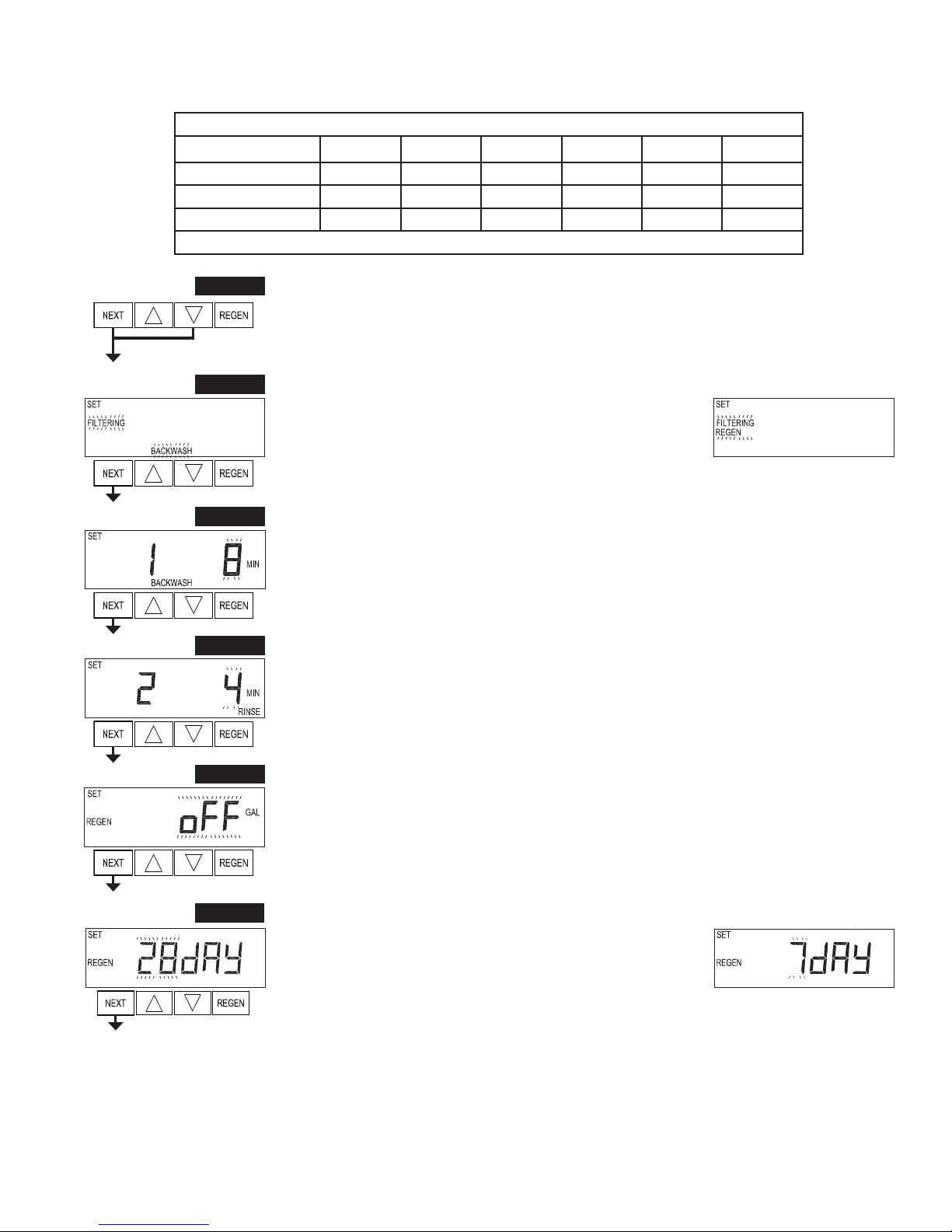
Step 2F – Choose FILTERING BACKWASH or FILTERING REGEN (see table) using ▲or ▼. Press
NEXT to go to Step 3F. Press REGEN to exit OEM Filter System Setup.
Step 2F
Step 3F – Select the time for the first cycle using ▲or ▼.
Press NEXT to go to Step 4F. Press REGEN to return to previous step.
Step 3F
Step 4F – Select the time for the second cycle using ▲or ▼.
If Step 2F is set to FILTERING REGEN, press NEXT to program the rest of the cycle times. If Step 2F is
set to FILTERING BACKWASH, press NEXT to go to Step 5F. Press REGEN to return to previous step.
Step 4F
Step 5F – Set Regeneration trigger using ▲or ▼. If value is set to:
• “oFF” regeneration will be triggered by the day override setting or can be set to regenerate on specific
days of the week.
• a number, regeneration will be triggered by the value specified (in gallons).
See Setting Options Table for more detail.
Press NEXT to go to Step 6F. Press REGEN to return to previous step.
Step 6F – Set Regeneration Trigger using ▲or ▼. If Step 5F is set to
OFF, Regeneration Trigger can be set to 28 day or 7 day.
Press NEXT to go to Step 7F. Press REGEN to return to previous step.
Step 5F
Step 6F

Page 16 EE Manual
Step 9F – Set Relay Actuation Time or Gallons using ▲or ▼. The choices are:
• Relay Actuation Time: After the start of a regeneration the amount of time that should pass prior
to activating the relay. The start of regeneration is defined as the first backwash cycle or brine cycle,
whichever comes first. Ranges from 1 second to 200 minutes.
• Relay Actuation Gallons: Relay activates after a set number of gallons has passed through the meter.
Ranges from 1 to 200 gallons.
Press NEXT to go to Step 10F. Press REGEN to return to previous step.
Step 9F
Step 10F – Set Relay Deactivate Time using ▲or ▼.
• If Set Time on is selected in Step 8F the relay will deactivate after the time set has expired. Ranges from 1
second to 200 minutes.
• If Set Gallons Filtering on or Set Gallons Filtering Regen on is selected in Step 8F the relay will
deactivate after the time set has expired or after the meter stops registering flow, whichever comes first.
Ranges from 1 second to 20 minutes.
Press NEXT to exit OEM Filter System Setup. Press REGEN to return to previous step.
Step 10F
EXIT OEM FILTER SYSTEM SETUP
Step 8F – Set Relay Operation using ▲or ▼. The choices are:
• Time on: Relay activates after a set time at the beginning of a
regeneration and then deactivates after a set period of time. The start of
regeneration is defined as the first backwash cycle or Dn brine cycle,
whichever comes first.
• Gallons Filtering on: Relay activates after a set number of gallons
have been used while in service and then deactivates after the meter stops registering flow and the set time
period has expired.
• Gallons Filtering Regen on: Relay activates after a set number of gallons have been used while in service,
or during regeneration, and then deactivates after the meter stops registering flow and the set time period
has expired.
•ERROR: Relay closes whenever the valve enters error mode, and immediately deactivates when error
mode is exited. If set to ERROR, Steps 9F and 10F will not be shown.
• Off: If set to Off, Steps 9F and 10F will not be shown.
Press NEXT to go to Step 9F. Press REGEN to return to previous step.
Step 8F
Step 7F – Set Regeneration Time Options using ▲or ▼. NOTE: This step will not appear if Step 5F is set
to oFF or Step 5CS is set to “SYS”.
If value is set to:
• “NORMAL” means regeneration will occur at the preset time;
• “on 0” means regeneration will occur immediately when the volume capacity reaches 0 (zero); or
• “NORMAL + on 0” means regeneration will occur at one of the following:
— the preset time when the volume capacity falls below the reserve or the specified number of days
between regenerations is reached whichever comes first; or
— immediately after 10 minutes of no water usage when the volume capacity reaches 0 (zero).
“NORMAL” is the default if Step 5CS is set to ALT A or ALT B, and “NORMAL + on 0” is not available.
“on 0” is the default if Step 2CS is set to 1.0T , and “NORMAL + on 0” is not available.
See Setting Options Table for more detail. Press NEXT to go to Step 8F. Press REGEN to return to previous
step.
Step 7F
EE Manual Page 17
Installer Display Settings - Regeneration Type Auto
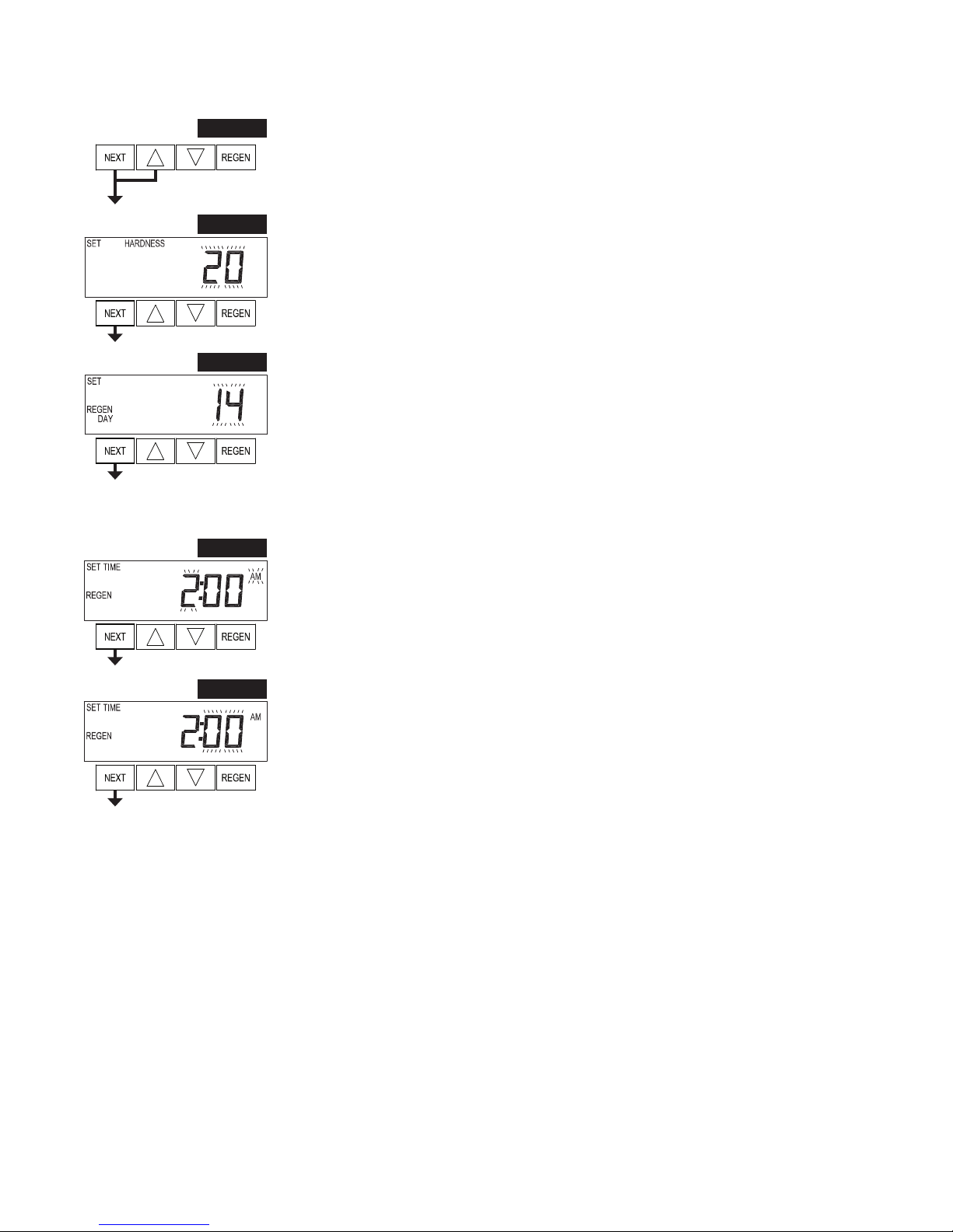
Step 1I - To enter Installer Display press NEXT and ▲simultaneously for about 5 seconds and release.
Step 1I
Step 2I – Hardness: Set the amount of influent hardness using ▲or ▼. This display will not be viewed
if FILTERING BACKWASH or FILTERING REGEN is selected in Step 2F or if “oFF” or a number was
selected in Step 11S.
Press NEXT to go to step 3I. Press REGEN to exit Installer Display Settings.
Step 2I
Step 3I – Day Override: When volume capacity is set to “oFF”, sets the number of days between
regenerations. When volume capacity is set to AUTO or to a volume, sets the maximum number of days
between regenerations. If value set to “oFF”, regeneration initiation is triggered solely by volume used.
If value is set in days (allowable range from 1 to 28) regeneration initiation will be called for on that day
regardless of actual water usage. Set Day Override using ▲or ▼:
• number of days between regeneration (1 to 28); or
• “oFF”.
See Setting Options Table for more detail on setup.
Press NEXT to go to step 4I. Press REGEN to return to previous step.
Step 3I
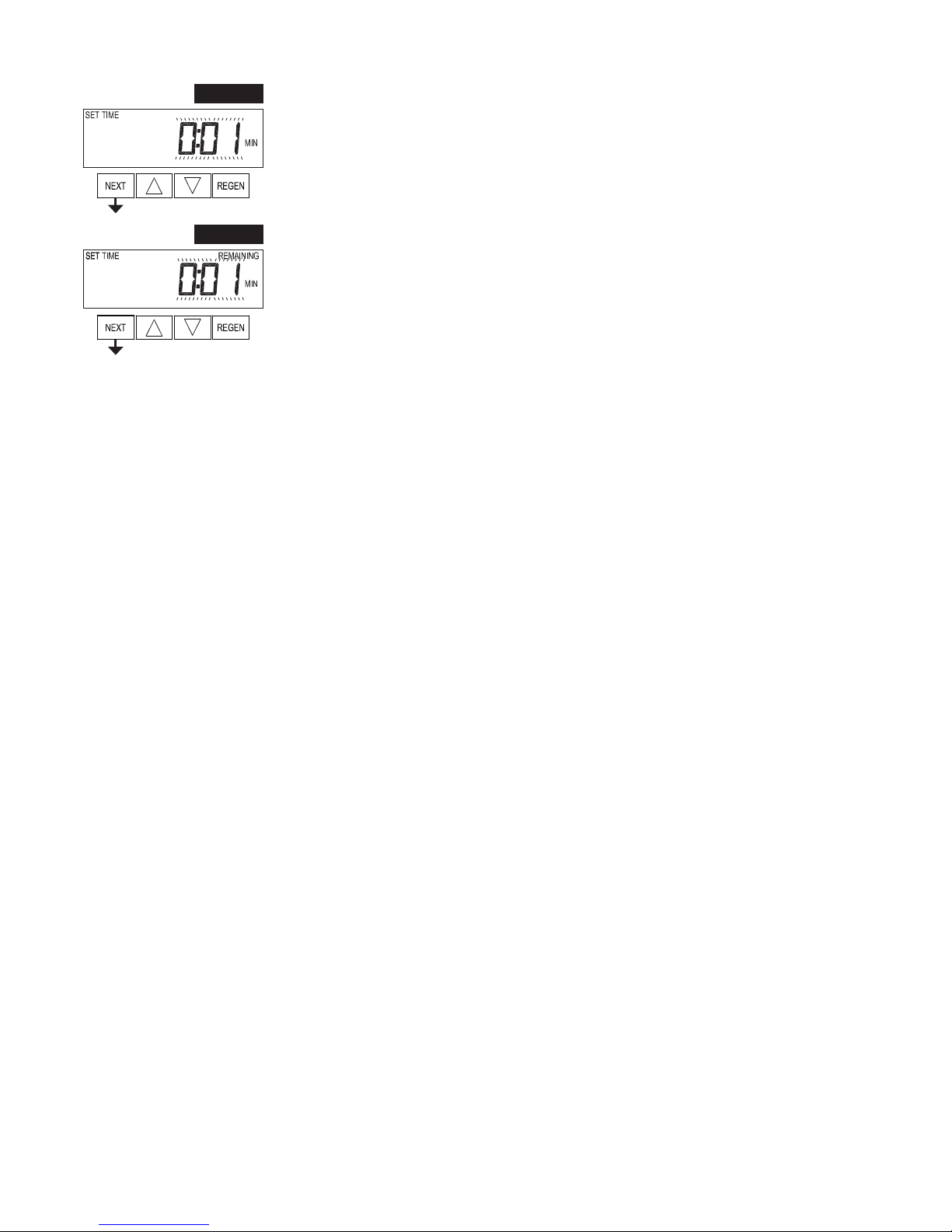
Step 4I – Next Regeneration Time (hour): Set the hour of day for regeneration using ▲or ▼. The default
time is 2:00. This display will show “REGEN on 0 GAL” if “on 0” is selected in Set Regeneration Time
Option in OEM Softener System Setup or OEM Filter System Setup.
Press NEXT to go to step 5I. Press REGEN to return to previous step.
Step 4I
Step 5I – Next Regeneration Time (minutes): Set the minutes of day for regeneration using ▲or ▼. This
display will not be shown if “on 0” is selected in Set Regeneration Time Option in OEM Softener System
Setup or OEM Filter System Setup.
Press NEXT to exit Installer Display Settings. Press REGEN to return to previous step.
Step 5I
EXIT INSTALLER DISPLAY SETTINGS

Page 18 EE Manual
Installer Display Settings - 28 Day Regeneration
Step 1I - To enter Installer Display press NEXT and ▲simultaneously for about 5 seconds and release.
Step 1I
Step 2I – Day Override: When volume capacity is set to “oFF”, sets the number of days between
regenerations. Set Day Override using ▲or ▼number of days between regeneration (1 to 28).
See Setting Options Table for more detail on setup.
Press NEXT to go to step 3I. Press REGEN to return to previous step.
Step 2I
Step 3I – Next Regeneration Time (hour): Set the hour of day for regeneration using ▲or ▼. The default
time is 2:00. Press NEXT to go to step 4I. Press REGEN to return to previous step.
Step 3I
Step 4I – Next Regeneration Time (minutes): Set the minutes of day for regeneration using ▲or ▼.
Press NEXT to exit Installer Display Settings. Press REGEN to return to previous step.
Step 4I

EE Manual Page 19
Installer Display Settings - 7 Day Regeneration
Step 1I - To enter Installer Display press NEXT and ▲simultaneously for about 5 seconds and release.
Step 1I
Step 2I – Use ▲or ▼to set the current day of the week.
Default = 4 (Wednesday)
1 = SUNDAY
2 = MONDAY
3 = TUESDAY
4 = WEDNESDAY
5 = THURSDAY
6 = FRIDAY
7 = SATURDAY
Press NEXT to go to Step 3I. Press REGEN to exit Installer Display.
Step 2I
Step 3I – Scroll through days 1 to 7 using NEXT. Use ▲or ▼to turn regen ON or OFF for each individual
day. After completing the 7th day, press NEXT to go to Step 4I. Press REGEN to go to previous display.
Step 3I
Step 4I – Next Regeneration Time (hour): Set the hour of day for regeneration using ▲or ▼. The default
time is 2:00. Press NEXT to go to step5I. Press REGEN to return to previous step.
Step 4I
Step 5I – Next Regeneration Time (minutes): Set the minutes of day for regeneration using ▲or ▼.
Press NEXT to exit Installer Display Settings. Press REGEN to return to previous step.
Step 5I
Page 20 EE Manual
Diagnostics
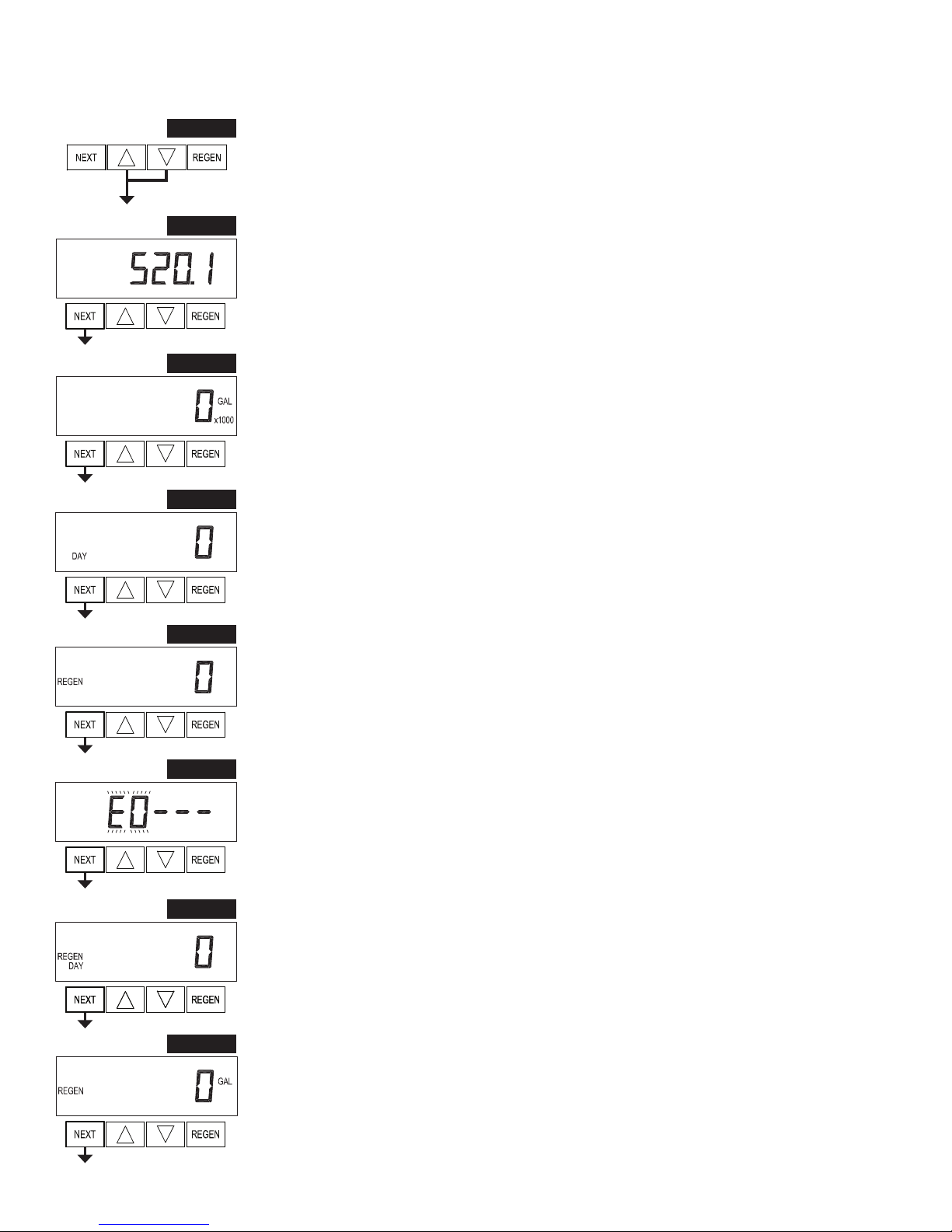
Step 1D - Press ▲and ▼simultaneously for 5 seconds and release. If screen in Step 2D does not appear
the lock on the valve is activated. To unlock press ▼, NEXT, ▲,REGEN in sequence, then press ▲and ▼
simultaneously for 5 seconds and release.
Step 1D
Step 2D – Software Version. Press NEXT to go to Step 3D. Press REGEN to exit Diagnostics.
Step 2D
Step 3D – Volume, total used since start-up: This display shows the total gallons treated since startup. This
display will equal zero if a water meter is not installed. Press the NEXT button to go to Step 4D. Press
REGEN to return to previous step.
Step 3D
Step 4D – Days, total since start-up: This display shows the total days since startup. Press the NEXT button
to go to Step 5D. Press REGEN to return to previous step.
Step 4D
Step 5D – Regenerations, total number since start-up: This display shows the total number of regenerations
that have occurred since startup. Press the NEXT button to go to Step 6D. Press REGEN to return to
previous step.
Step 5D
Step 6D – Error Log: This display shows a history of the last 10 errors generated by the control
during operation. Press ▲or ▼to view each recorded error.
Press NEXT to go to Step 7D. Press REGEN to return to previous step.
Step 6D Step 6D – Error Log: This display shows a history of the last 10 errors generated by the control
during operation. Press ▲or ▼to view each recorded error.
Press NEXT to go to Step 7D. Press REGEN to return to previous step.
Step 7D – Days, since last regeneration: This display shows the days since the last regeneration occurred.
Press NEXT to go to Step 8D. Press REGEN to return to previous step.
Step 7D
Step 8D – Volume, since last regeneration: This display shows the volume of water that has been treated
since the last regeneration. This display will equal zero when a water meter is not installed. Press NEXT to
go to Step 9D. Press REGEN to return to previous step.
Step 8D
Table of contents
Other Water Specialist Control Unit manuals

Water Specialist
Water Specialist WS1CT User manual

Water Specialist
Water Specialist WS2H User manual

Water Specialist
Water Specialist WS1HR User manual

Water Specialist
Water Specialist WS2HF User manual

Water Specialist
Water Specialist WS1TC Guide

Water Specialist
Water Specialist CK User manual

Water Specialist
Water Specialist WS1TT User manual

Water Specialist
Water Specialist WS1CC Guide
Popular Control Unit manuals by other brands


Kohler
Kohler Mastershower K-406 installation guide

JBL
JBL ProFlora V002 Instructions for use

AquaScape
AquaScape 48026 Instructions & maintenance

Cooper
Cooper Scantronic 8844 installation guide

AMOT
AMOT G Series Operation, installation, and maintenance manual

RadioPopper
RadioPopper L-358 quick start guide


