Waterite Vectapure II RO-4042H Installation instructions

VECTAPURE II™
Residential Reverse Osmosis Water System
INSTALLATION AND OWNER’S MANUAL
For Vectapure II™models RO-4042H, RO-4052H, RO-4152H and
all
WR2 series reverse osmosis systems
THIS MANUAL IS TO BE LEFT WITH THE OWNER OF THE EQUIPMENT FOR
REFERENCE PURPOSES AND TECHNICAL GUIDANCE. IT IS STRONGLY
RECOMMENDED THAT QUALIFIED DEALER SERVICE PERSONNEL BE
CONTACTED IN THE EVENT OF AN UNKNOWN INTERRUPTION OF SERVICE OR
APPARENT PRODUCT MALFUNCTION. AN ANNUAL PREVENTATIVE
MAINTENANCE INSPECTION BY A WATER PROFESSIONAL IS RECOMMENDED TO
ENSURE TROUBLE-FREE AND CONTINUOUS OPERATION.
R5

2
Congratulations!
You have purchased the finest residential reverse osmosis
water system available for your home. It will provide you years
of reliable service if properly installed, operated and
maintained. Please read this entire manual before attempting
installation and operation.
Section 1. Frequently Asked Questions
Before getting started, take the time to familiarize yourself with your new Waterite system
by reading some FAQs listed below. Call us or ask your dealer if you have any other
questions about your system’s operation.
Q: How does the Vectapure II™ Residential Reverse Osmosis System differ from an
ordinary water filter?
Ordinary water filters use a screen to separate only particles of dirt and sediment from the raw
water source. Reverse osmosis employs a semi-permeable membrane that removes not only
particles but also a very high percentage of dissolved contaminants, molecule by molecule, from
your raw tap water. Your system will deliver pure, bottled water quality water to a faucet
conveniently located at your kitchen sink or any other designated area.
Q: What is the membrane and how does it work?
The membrane element consists of several thin layers or sheets of film that are bonded together
and rolled in a spiral configuration around a plastic tube. As the raw water passes across the
surface of the membrane, only pure water molecules are allowed to pass through and collect in the
tube, while all other mineral and contaminant molecules are rejected and washed from the surface
of the membrane to the drain.
Q: What processes does the Vectapure II™ RO system use?
Vectapure™ systems use either 4 stages or 5 stages of treatment to produce your drinking water.
The raw tap water first flows through a combo carbon and 5-micron particle filter to remove
chlorine, chemicals, dirt, rust and other sediment. The third stage is a 1-micron sediment filter that
is used to reduce very fine suspended particles (this stage is omitted in a 4 stage system). The
fourth stage is the reverse osmosis membrane that separates most dissolved contaminants from
the water molecules. The final stage is a block carbon filter that eliminates all remaining traces of
taste and odour that the water may have absorbed from the holding tank or the plumbing system.
Vectapure II models and WR2 models both use a 10” filter housing for this last filtration stage.
Your system also includes a holding tank for the purified water, a faucet and the hardware and
tube needed to complete the installation.
Q: Will reverse osmosis remove sodium and salts from the water?
Yes. Reverse osmosis was originally developed to make drinking water from seawater. Your
system is equipped with a membrane that will be very effective in reducing sodium levels normally
found in ground water or softened water. This is particularly important for those with restricted
sodium diets. Vectapure II and WR2 Series systems are not designed for use on seawater.

3
Q: Does reverse osmosis remove bacteria? Cryptosporidium? Viruses?
Reverse osmosis membranes will virtually eliminate most chemicals, bacteria, viruses and
parasites such as Cryptosporidium from the water. Where these conditions exist, pre-filters and
other system components located before the membrane will become contaminated from exposure
to them. Cross contamination of the entire system may occur when the membrane or filters are
changed or disturbed. Vectapure II and WR2 RO models have incorporated the ability to flood the
RO system, right up to the kitchen sink faucet, with chlorinated water to allow a periodic
disinfection of the unit, usually at the time that the prefilter cartridges are changed. Make sure
that you carefully follow the maintenance and sani-purging instructions provided.
!
THIS REVERSE OSMOSIS WATER SYSTEM IS DESIGNED ONLY TO IMPROVE AESTHETIC
PROPERTIES AND IS NOT DESIGNED TO ACT AS A PRIMARY BARRIER TO WATERBORNE
MICROBIOLOGICAL OR TOXIC CHEMICAL CONTAMINATION. WHERE THESE
CONDITIONS MAY EXIST CONSULT A WATER PROFESSIONAL TO ENSURE SUFFICIENT
RAW WATER PRE-TREATMENT AND DISINFECTION.
!
WATERITE RO SYSTEMS ARE TO BE OPERATED ONLY WITH A SAFE, CHLORINATED
RAW WATER SOURCE.THIS IS NECESSARY TO PERIODICALLY PURGE AND FLUSH THE
SYSTEM WITH WATER THAT HAS A CHLORINE RESIDUAL TO SANITIZE PARTS OF THE
SYSTEM THAT NORMALLY ARE EXPOSED TO WATER THAT HAS BEEN DECHLORINATED
AND MAY BE SUSCEPTIBLE TO BACTERIAL CONTAMINATION. FOLLOW SANI-PURGE
AND FLUSH INSTRUCTIONS AND CHANGE FILTER CARTRIDGES AT RECOMMENDED
INTERVALS.
Q: What other contaminants does reverse osmosis remove?
The combined filtering and RO processes in your system will remove more than 98% of many
organic compounds, including THMs (chloroforms), DBCP, lindane, TCE (trichloroethylene), PCE
(tetrachloroethylene), carbon tetrachloride and chlorine. Conservatively, Vectapure™ TFC
membranes will remove the following percentages of contaminates: Barium 97%, Potassium 92%,
Bicarbonate 94%, Radium 97%, Cadmium 97%, Selenium 97%, Calcium 97%, Silicates 96%,
Chromium 92%, Silver 85%, Copper 97%, Sodium 92%, Detergents 97%, Strontium 97%, Fluoride
90%, Sulphates 97%, Lead 97%, PCBs 97%, Magnesium 97%, Insecticides 97%, Nickel 97%,
Herbicides 97%, Nitrates 80%, Total Dissolved Solids 97%.
Q: What does RO treated drinking water taste like?
As most of the chemicals, organics and minerals are removed, your water will taste similar to
distilled water or low-mineral bottled water. Most people enjoy the natural flavour and the soft
texture. You will immediately notice that brewed coffee and juices from concentrate have a greatly
enhanced taste and aroma.

4
Q: Where is the system installed?
Typically, the system is installed under the kitchen sink. Some homeowners or installers prefer the
basement or crawlspace, as this conserves storage in the kitchen and may allow for easier access
to the system for maintenance purposes.
If you install the system more that 20’ from your faucet, you may need a product water booster
pump to ensure adequate pressure at the faucet. Your dealer can provide you with this optional
equipment.
Q: Can the Vectapure II™ system be connected to an extra faucet?
Yes. Many installations will include an optional ¼” line to refrigerator icemakers or additional sink
faucets. See your dealer for advice and parts.
Q: What factors affect the quantity and the quality of the water produced?
1. Pressure: The greater the water system pressure, the greater the water quantity that will be
produced. 60PSI is optimal, but it should never exceed 90PSI. Where water pressures are
low (<40PSI), a booster pump on the raw water line can be added to increase production.
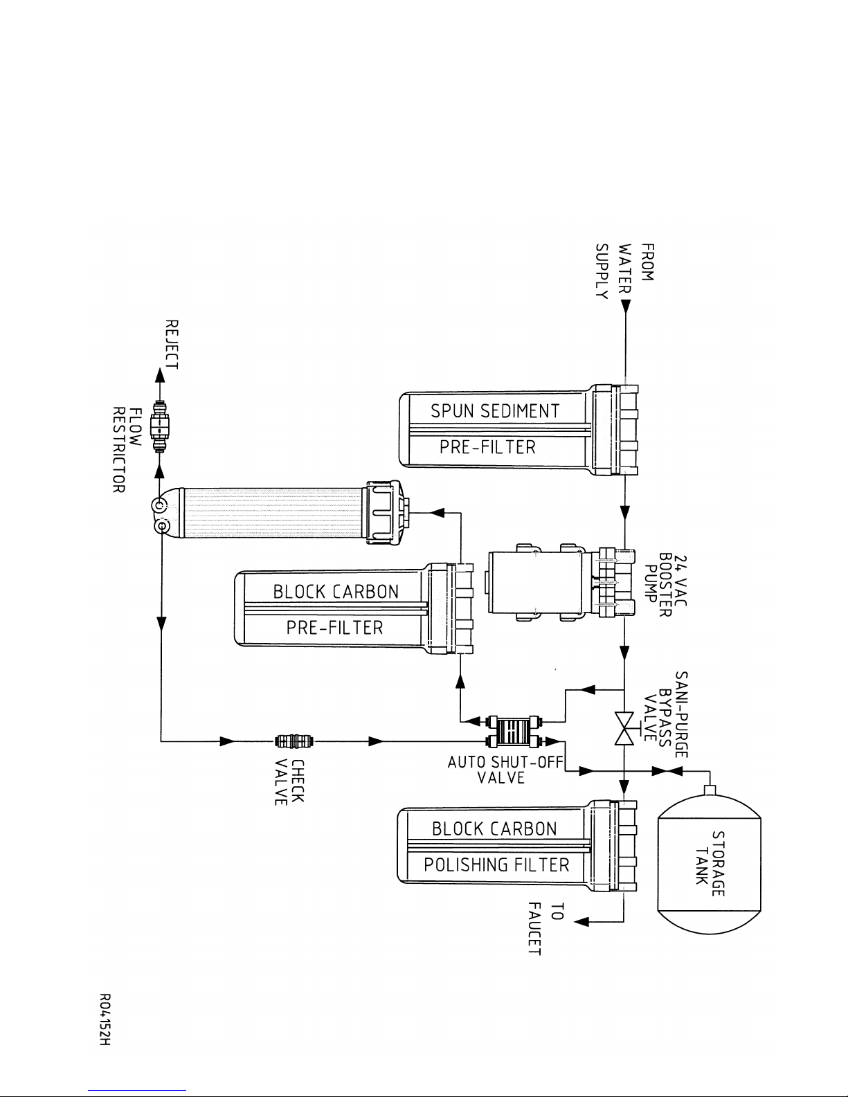
The RO-4152H comes equipped with a booster pump as standard equipment.
2. Temperature: Production increases with temperature, the optimal being 76F. Never
operate the system from the hot water line or with water exceeding 85F, as this will
damage the membrane.
3. Membrane type: Vectapure II systems use premium quality TFC (Thin Film Composite)
membranes, specially chosen for household applications.
4. TDS: The higher the Total Dissolved Solids in the raw water, the lower the output of
product water. Booster pumps are used to increase system pressure and overcome lower
output caused by higher TDS. System pressure may not however, exceed 90PSI.
Q: How much water does the Vectapure II™ system produce?
All Vectapure™ systems use membranes nominally rated for 75GPD. Actual output will be
dependent upon the factors explained above. In optimal applications (with a booster pump) you
may expect 60-70 gallons to be available over 24 hours.
Q: Can the amount of water produced be increased?
Filling a water pitcher for the refrigerator will allow more production overnight. A larger holding
tank (available from your dealer) will allow for more water to be on hand. Booster pumps will also
increase daily production.
Q: What is the standard warranty with the Vectapure II™ system?
Every Vectapure II™ system comes with a standard one-year limited warranty on all parts and
repair labour. A detailed warranty card is included with the unit. You may purchase and
extended warranty if you wish - see the enclosed Extended Warranty Program information
sheet and enrolment form included in your package. Call your dealer if you wish to have
one sent to you. Normal filter cartridge replacement is excluded from your warranty.
Q: What is the maintenance schedule for the Vectapure II™ system?
A good rule of thumb is to replace all pre-filters every three months. This is critical to ensure that
chlorine does not attack the membrane film. The carbon post-filter should be changed every three
to six months. When the old cartridges have been removed, the system should be purged and
flooded with chlorinated water before the new cartridges are installed. Dependent upon local
water conditions, your membrane should have a life expectancy of 1-5 years. More severe water
conditions (iron, hardness) may shorten this significantly; soft water sources may allow a
membrane life of up to 8 years.

5
Q: When should the membrane be changed?
If you notice gradually decreasing production from your system, differing taste to your drinking
water or a white scale forming on pans or dishes, it probably means that your membrane is
deteriorating and is losing its effectiveness. You may purchase a pocket TDS meter from your
dealer - this is the best way to assure you system is operating efficiently.
Section 2. Unpacking and Installation
Your system includes: Carton Contents
The main RO/filter unit assembly with 4 or 5 stages. The RO-4152H model will include a
booster pump mounted on the main bracket;
One membrane (in a sealed plastic bag), one combo carbon/sediment filter cartridge, one
block carbon filter cartridge and one polypropylene sediment cartridge (no white sediment
cartridge with RO-4042H);
One drain fitting and clamp with push-on tube fitting;
One cold water supply adapter;
One low-lead (stainless is optional) long reach Quick Faucet and mounting hardware;
Two #10 X1” Wall mounting screws;
5 m (15’) - white ¼” Poly tubing for water connections;
3m (10’) – black ¼” Poly tubing for drain connections;
One plastic tank shut-off valve;
One filter housing wrench;
One Owner’s package including owner’s manual, warranty certificate, Extended Warranty
Plan enrolment form, Waterite Parts Program enrolment form;
One 12 litre (4 gallon) RO holding tank.
Step 1. Selecting the System Location
1. This reverse osmosis system is designed for installation under a sink. It can however, be
mounted anywhere within 20 feet of the faucet, such as the basement or adjoining utility
room. Keep in mind that filter housings will need periodic replacement and that easy
access must be maintained. Do not install in a location with high humidity, direct sun or a
direct source of heat. Both the RO system and the tank may be installed horizontally or
vertically. If you are installing a RO 4152H model, you will need a standard 110V plug
nearby. Figure 1.
Booster pump (RO-4152H)
Holding Tank and valve
Mounting bracket Membrane housing
Faucet and mounting hdwe Sani-purge valve
Carbon post-filter
Sediment pre-filter Drain clamp and fitting
Membrane element
Water supply adapter
Combo pre-filter 5m ¼” poly tube (clear)

6
Keep in mind that you may install a tube tee on the line to the faucet to connect icemakers
or other faucets to the system. If you locate your system farther than 20 feet from the
faucet, you will need to use 3/8” tubing or install a pressure booster pump to your line. See
your dealer for parts and details.
Step 2. Getting Ready
1. Clear working area. Unpack all components and check for visual damage. Ensure all
listed components are included.
2. Inspect the cold water supply line and the condition of the pipe. The water supply adapter
included is intended to be installed between the supply valve and the faucet connector,
under the kitchen sink. If the cold water supply valve is not available at the installation
location, you will need to consult your plumber or plumbing supply store to purchase an
appropriate cold water connection.
3. Check the air pressure in the RO storage tank with an ordinary tire gauge. It should be
pre-charged to 7-10 PSI. Adjust if necessary. DO NOT EXCEED RECOMMENDED TANK
INFLATION PRESSURE –UNIT WILL FAIL TO OPERATE CORRECTLY.
4. You will need the following tools: An electric drill, a ½” carbide bit, a ¼” carbide bit, a 1/8”
carbide bit, a pencil, a small adjustable (crescent) wrench, a sharp knife (X-Acto type knife
is best), Teflon plumbing tape, adjustable pliers, a rat-tail file, a center punch, a medium flat
head screwdriver, a small household funnel. Always wear eye protection when using an
electric drill.
Step 3. Install the Cold Water Supply Faucet Adapter
1. Turn OFF the COLD water supply valve to your kitchen faucet.
2. Turn ON the COLD water on your kitchen faucet to release all the pressure, and completely
drain the cold water until the water flow stops.
3. Place some towels underneath the cold water supply valve and then disconnect the faucet
supply tube from the cold water supply valve.
4. Wrap male threads on both cold water supply valve and the water supply adapter 4 to 5
times with plumber’s (Teflon) tape.
5. Install the water supply adapter on the cold water supply valve. Do not over-tighten.
6. Install the faucet supply tube to the water supply adapter.
7. Connect the white ¼” tube to the water supply adapter by inserting the tube firmly and
pushing until the tube end contacts the stop. Gently tug the tube backwards to assure a
secure connection. In the same way, connect the other end of the tube to the RO system
water inlet.
8. Keep the COLD water supply valve OFF until the RO system installation has been
completed; turn the COLD water supply valve ON and check for leaks around the water
supply adapter. Tighten, reseal or reinstall if necessary.

7
Step 4. Install the Sink Faucet
Tools required for this step: An electric drill, a 5/8” carbide bit, a small adjustable wrench, a center
punch, a pencil, a rat-tail file.
1. Examine the sink. If it has an existing hole for mounting a faucet, skip to Step 4. (6).
2. Locate and mark the spot you wish to install the faucet. Make sure it does not interfere
with operation of the main faucet and that there is clearance for plumbing and mounting
hardware directly below it under the sink or countertop. If you have a stainless sink, go to
Step 4. (5)
3. If you have a concrete sink with a thickness of less than 1”, the faucet can be mounted
directly to sink. If the thickness exceeds 1”, the faucet must be mounted directly on the
countertop or a faucet with an extended shank must be used. Tool substitution: Use a 5/8”
masonry bit to drill the concrete sink.
4. If you have a porcelain enamel or ceramic sink, it is strongly recommended that a
professional install the faucet to avoid chipping and damaging the sink finish.
5. Mark the spot chosen for the faucet hole with the pencil. Use the center punch to slightly
indent the spot (the center punch is unnecessary for concrete sinks). Use the 5/8” bit and
drill the hole. Use the rat-tail file to smooth any burrs or rough edges on the hole.
6. The sink faucet may now be assembled to the sink or countertop using the assembly
procedure shown in Figure 2. Your faucet may have the poly tube factory pre-attached. If
so, do not connect the tube to anything at this time. If the tube is not pre-attached, do not
attach the poly tube to faucet at this time.
Figure 2.
Step 5. Install the Drain Saddle Assembly
1. Select the location to install the drain saddle assembly. This is usually on the sink
drainpipe and needs to always be located above the “S” trap.

8
2. Position the drain saddle assembly in the selected location and mark the spot through the
threaded outlet with a pencil or marker
3. Drill a ¼” hole at the marked spot. Strip the backing paper from the adhesive side of the
saddle gasket and position on the inside of the drain saddle, aligning the hole with the
threaded outlet. Attach the drain saddle to the drainpipe, aligning the push-on port with the
drilled hole. Tighten the clamp snugly. DO NOT OVER TIGHTEN.
4. The black drain tube may be inserted directly into the push-on drain port, using instructions
in Step 8. below. Do not attach poly tube at this time.
Step 6. Install the Tank Valve, Preparing the Storage Tank
1. Wrap the threaded storage tank nipple with two wraps of Teflon tape. Thread on tank shut-
off valve until snug. Using the wrench, turn an additional ¼ turn. DO NOT OVER
TIGHTEN. Open tank valve to the fully open position.
Step 7. Mounting the RO Unit
1. While holding the RO unit in its mounting position, mark the holes for the wall screws.
Using a 1/8” bit, drill the pilot holes for the screws. Screw in the mounting screws leaving
¼” protruding. Hang the RO mounting bracket on the screws and tighten.
2. If the unit is to be mounted on wallboard, use plastic screw anchors, available at any
builder’s supply and follow the manufacturer’s directions.
3. DO NOT INSTALL FILTER CARTRIDGES OR THE RO MEMBRANE AT THIS TIME.
Spin the filter housing sumps on to the RO unit and hand-tighten. On Vectapure II units the
clear housing always is installed on the right-hand side. WR-2 Series use only white
opaque housings. Use the wrench provided to turn an additional ¼ turn.
Step 8. Connect the System Tubing
!
Making and securing a push on connection is simple. First, the
tubing should be cut square and any burrs or rough edges
removed. Insert the tube firmly and push until the tube end
contacts the stop. Gently tug the tube backwards to assure a
secure connection. To disconnect, pull the tube while
pushing in the collet ring. The joint may be used over and over
again, if necessary.
1. Connect the cold water supply valve to the first filter housing water inlet push-on fitting
(marked “water inlet”), after cutting the ¼” clear tube to the length required.
2. Connect the black ¼” tube from the end of the flow restrictor (marked “to drain”) to the
Drain Saddle push-on connection (your black drain tube may be pre-attached to your RO).
Please note that the drain line flow restrictor has been installed INSIDE the black drain tube

9
at the waste elbow, on the membrane housing. Place the storage tank in the location you
have chosen for it. Using the clear 3/8” tube connect the system fitting marked “to tank” to
the tank valve. Connect the 3/8’” tube attached to the faucet to the system fitting marked
“to faucet”. If the tubing is not pre-attached to the faucet, cut the 3/8” clear tubing to the
desired length and attach the tube to the fitting at the base of the faucet shank to the fitting
marked “ to faucet” on the RO unit.
3. You may find that your unit does not have labels attached to indicate the water line and
drain line connections. The photos below are labelled with the correct locations for the
water and drain connections.
To Storage Tank
Raw Water Inlet
To Drain
To Faucet
Top View Back View
Step 9. Filling and Sani-Flushing the System
1. Turn on the feed water adapter valve and check all connections for leaks. Do not proceed
further until any leaks are fixed.
2. Let the RO system and the storage tank fill with water. Open the faucet at the sink and let
the water run free for 10 minutes. Turn the saddle valve OFF. Leave the faucet open and
drain all the water from the tank until water flow stops.
!
THOROUGHLY WASH HANDS BEFORE LOADING CARTRIDGES AND MEMBRANE
ELEMENTS.
3. a) Vectapure II Models: Remove the clear prefilter housing by turning counter clockwise
with the housing wrench supplied. Remove all protective wrapping from the filter
cartridges. Insert the 5-micron combo carbon/sediment filter cartridge in the clear housing
and reassemble housing. The housings are seated with o-rings –DO
NOT OVER TIGHTEN –1/4 turn after hand tight is usually sufficient.
Repeat with the white 1-micron sediment cartridge in the middle
housing (RO-4052H and RO-4152H only). Install carbon block
cartridge in the remaining white filter housing and reassemble.
4. b) WR2 Models: Remove the left housing by turning clockwise with
the housing wrench supplied. Remove all protective wrapping from
the filter cartridges. Insert the 5-micron white sediment cartridge
(carbon cartridge in two-housing WR2 units) in the housing and
reassemble. The housings are seated with o-rings –DO NOT OVER

10
TIGHTEN –1/4 turn after hand tight is usually sufficient. Repeat with one of the carbon
block cartridges in the middle housing (three-housing WR2 units only) and with the other
carbon block cartridge in the right hand housing.
5. Remove the membrane element from its wrapping. Disconnect the ¼” tube attached to the
membrane housing end cap. Unscrew the end cap from the membrane housing. The
membrane housing is mounted horizontally on the system’s mounting bracket. See Figure
1. Insert the membrane element into the housing, o-ring spigot first. Gently push until the
membrane seats snugly inside the housing. Re-install housing cap and poly tube.
Step 10. Starting Up the System
1. Make sure that the Sani-purge valve (see figure 4.) is CLOSED. Open cold water
supply valve and let RO system fill with water. Check for leaks and tighten any joints if
necessary
2. Model RO-4152H only: Insert the plug into a standard wall receptacle. System pump will
switch on and begin to operate.
3. Let the system operate for about 10 minutes. Close the storage tank valve and open the
faucet until product water drips out. Check for leaks again and fix if necessary.
!
DO NOT USE ANY WATER FROM THE SYSTEM UNTIL THE NEXT STEP IS COMPLETE.
4. Open the storage tank valve and close the faucet. The system is now operating and filling
the storage tank. Allow the tank to fill completely and the system to automatically shut itself
off. This step may take 1-3 hours or more. Open the faucet and let the entire tank drain
completely. You will see dark carbon dust briefly flush from the carbon filer cartridge –this
is harmless and normal for the first flow of water through the cartridge. Allow the system to
re-fill the tank. Once completed, your system is ready for use.
Section 3: Operation and Maintenance
Operation of your Reverse Osmosis System is simple and easy. This appliance is fully automatic
and can be enjoyed without complicated operating procedures. Be sure to follow the cartridge
replacement schedule to ensure peak performance and long membrane element life.
Changing Filter Cartridges and Sani-Purge Procedure
The filter cartridges should be changed, as a rule of thumb, every three months. It is critical that
this be done, to ensure that chlorine is not allowed to attack the membrane film. Always Sani-
purge the complete system at the same time that the cartridges are changed.
!
THOROUGHLY WASH HANDS BEFORE LOADING CARTRIDGES AND MEMBRANE
ELEMENTS.

11
1. Close the cold water supply valve. Open the faucet and completely drain until the flow of
water stops. Remove the filter housings with the housing wrench and discard the old filter
cartridges. Thoroughly clean the inside of the housing bowls with soap and water. Rinse
completely. If the RO has been installed with a water supply that does not contain chlorine,
put 2 fluid ounces (60 ml) of common household chlorine bleach such as Javex in the clear
housing. Reassemble filter housings WITHOUT cartridges.
2. Sani-Purge Procedure: Turn the RO faucet off. Turn the blue-handled Sani-purge valve
(Figure 3.) to the ON position. Open the raw water supply saddle valve. The RO unit and
tank will now fill with raw, chlorinated water. Allow the system to stand for 1 hour.
Figure 4.
Sani-purge valve (shown in closed
position)
3. Turn the cold water supply valve OFF. Open the faucet and allow the system to completely
drain. Turn the blue Sani-purge valve OFF. They system has now been Sani-purged and
is ready to load the new cartridges.
4. To load the cartridges, repeat Step 9 (3) or (4) from the installation instructions above.
Turn the raw water supply valve ON. Allow the storage tank to fill and then drain it
completely and refill again before resuming use of the water system.
NOTE: The Sani-purge procedure does not expose the membrane element to chlorinated water
long enough to cause deterioration of the thin film and may be done safely with the membrane
element in place.
Changing the Reverse Osmosis Membrane
The membrane element will require changing much less frequently than the filter cartridges and
only when failure is indicated. This should be done when water production begins to noticeably
fall, or TDS readings in the product water begin to rise. Total Dissolved Solids may be measured
by a professional or by use of a simple hand-held TDS monitor. These are available from your
dealer or from Waterite’s Online Store at www.waterite.com.
Pocket TDS meter
The membrane element life will range from 1 to 5 years, depending on the quality of the raw water.
Soft water free from iron is ideal. Hardness, iron, chlorine and infrequently changed filter
cartridges are the membrane’s greatest enemies.

12
To change the membrane element, start by closing the cold water supply valve. Make sure that
your hands are washed and your tools are clean. Repeat Step 9 (5.) above. If the old membrane
element does not pull out easily by hand, use a pair of pliers to gently pull the element by the
product tube until it slides out of the housing. Use warm water, a mild soap solution and a
bottlebrush to clean the interior of the housing before installing the new element.
Your Warranty
Keep your bill of sale and your warranty certificate, included in this kit. This is needed to claim any
parts or repair service during the warranty period. Read the document completely for warranty
claim instructions.
!
BE SURE TO RETURN THE VECTAPURE WARRANTY CARD LOCATED IN YOUR
LITERATURE KIT. THIS IS NECESSARY TO VALIDATE YOUR PRODUCT WARRANTY.
Section 4: Troubleshooting Guide
Trouble Shooting Guide Possible Cause Solution
Low Water or No Water Water supply valve closed
or tank valve closed. Open valves
Low water pressure Install booster
pump
Crimped poly tube Repair or replace
tube
Raw water TDS high Consult dealer –
may need pre-
treatment
Filters or membranes plugged Replace filters
Combo filter(s) upside down Install with
rubber gasket up
Tubes installed to wrong fitting Install tubes per
S.8 (1), (2) and
(3).
Leaking Joints Fittings not seated Disconnect fitting
and reseat tube
Filter housing leaking Tighten with
housing wrench
Inspect o-rings
for cuts or crimps

13
VECTAPURE II™
and WR2 SERIES
RESIDENTIAL REVERSE OSMOSIS SYSTEMS
PARTS LIST
KEY
DESCRIPTION
PART NUMBER
COMMENT
KEY
DESCRIPTION
PART NUMBER
COMMENT
1
Filter housing - clear
HE1014CW-U
14
Mounting clips
WP-225
Filter housing - white
HE1014WW-U
2
Cartridge, combo
PPCC10-05
All models
16
Low pressure switch
RO-SWI-L
RO4152H only
Cartridge 1 mic. sediment
PP1001
RO4052H, RO4152H
18
Flow restrictor
069D
069E
(Pump model)
Cartridge, Carbon
CBC-5CTO
All models
19
High pressure switch
RO-SWI-H
RO4152H only
3
Male elbow, push-on, 1/4"
A4ME4
20
4-way shutoff valve
ROS002
Tee, push-on, 1/4"
A4TU4
21
RO storage tank
ROT-4
5
Sani-purge valve
A6HVUC6
22
Tank valve, push-on, 1/4"
EA3931
6
Mounting bracket
BK3R-3MW
Tank valve, push-on, 3/8"
EA3931
8
Transformer
LSA5436ADT
RO4152H only
23
PE tube - 1/4"
3634100
clear
9
Booster pump
PUMPAC-110T
RO4152H only
PE tube - 3/8"
3636100
clear
10
Mounting clips
WP-25
24
Plastic wrench
HAN-06W
11
Membrane
BME1812R75
25
Faucet
WDF103LBTAQ
12
Membrane housing
HM251EZ
29
Water supply adapter
H0630426
13
Check valve
CV1414EZ
30
Drain saddle
WP-14EZ
N/S
Membrane housing o-ring
RO-0202
N/S
Filter housing o-ring
RKE001
RKE020HE
Dual O-ring style

14
VECTAPURE II™
RESIDENTIAL REVERSE OSMOSIS SYSTEM
FLOW LAYOUT
RO4042H / RO4052H
Not included on
RO4042H

15
VECTAPURE II™
RESIDENTIAL REVERSE OSMOSIS SYSTEM
FLOW LAYOUT
RO415H

16
VISIT THE WATERITE TECHNOLOGIES WEBSITE FOR
INFORMATION, CONSUMER ONLINE REPLACEMENT PARTS
AND PRODUCT UPDATES AT:
www.waterite.com
Waterite Technologies, Inc.
3-75 Meridian Drive
Winnipeg, Manitoba
Canada R2R 2V9
(204) 786-1604
(204) 783-1599 fax
www.waterite.com
This manual suits for next models
2
Table of contents
Other Waterite Water Filtration System manuals

Waterite
Waterite Excelight EL411AK User manual

Waterite
Waterite VECTAPURE NX RO4053HNX Installation instructions

Waterite
Waterite TriPlex DuPlex FS-BB Series Installation instructions

Waterite
Waterite BLACKMAXX RB8 User manual

Waterite
Waterite Fusion 360 Installation instructions

Waterite
Waterite VECTAPURE RSX II User manual

Waterite
Waterite VECTAPURE RSX User manual

Waterite
Waterite Vectapure RSXII LITE User manual

Waterite
Waterite VECTAPURE 360 Installation instructions

Waterite
Waterite Vectapure NX Installation instructions