Accessories FLC210
– 139-2406 shield ES
– 139-2407 shield ET
– 139-2404 IO-180
– 139-2405 IW FLC210
Tools required
– Screwdriver TX20 / TX25
Driver boxes for operating the FLC210 / FLC210 PP
– 139-6978 Sep. Driver Box FLC210 TW
– 139-6979 Sep. Driver Box FLC210 CC
(Also available for through-wiring as an option)
5.91
1.73
FLC210 PP / FLC210 PP CC/TWFLC210 / FLC210 TW/CC
3.94
5.91
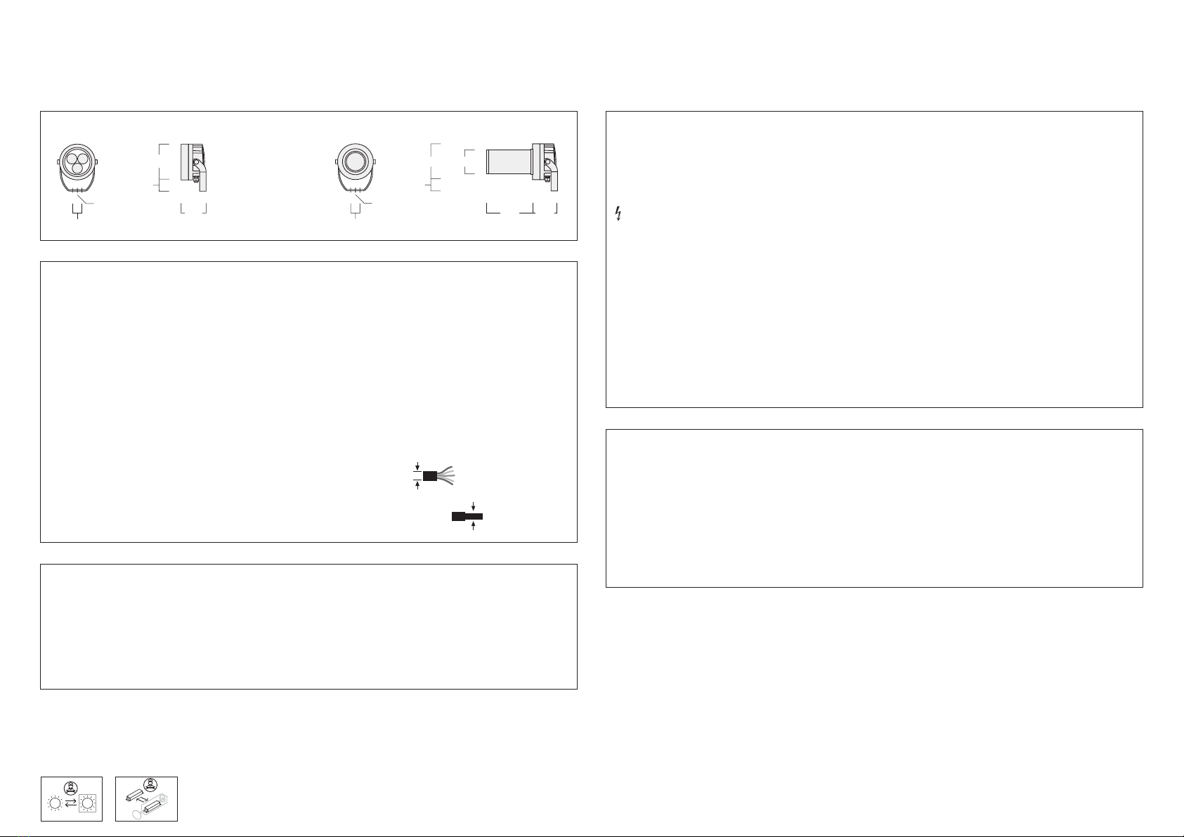
Projectors
IP66, IK07
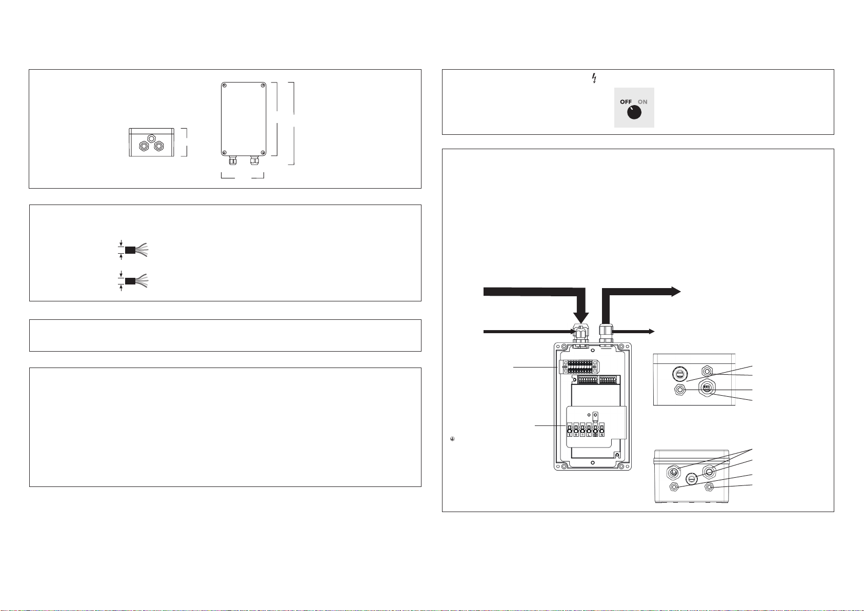
FLC210: 16 AWG
FLC210 CC/TW: 16 AWG
ø 0.177 – 0.394 in
Light source
FLC210 .................. 3 LED 6W / 9W / 12W
FLC210 PP ........................ 18W / 26W
TW and CC luminaires are always with a driver box /
operating device. For information and luminaire
connection, see the attached connection/wiring
diagram.
FLC210-TW ........................ 3 LED 11W
FLC210 PP-TW ........................... 10W
FLC210-CC .........................3 LED 12W
FLC210 PP-CC ........................... 15W
FLC210 .......................Class I, ta=25 °C
FLC210-TW ....................Class I, ta=25 °C
FLC210-CC ............................Class III
Windage area
FLC210 .............................. 0.194 ft²
FLC210 PP ........................... 0.377 ft²
Weight
FLC210 ............................max. 6.6 lb
FLC210 PP .........................max. 8.8 lb
120-
277 V
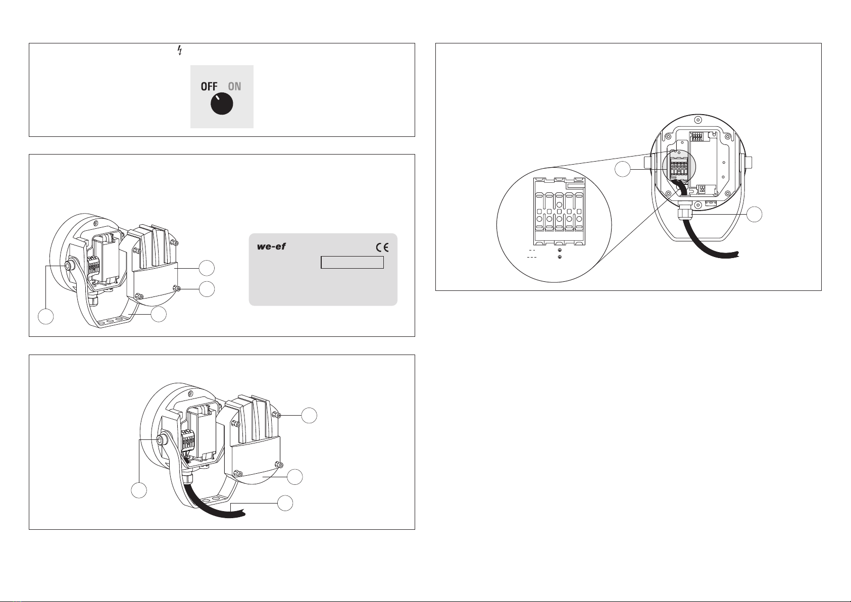
Installation
The product must be installed and maintained by
a suitably qualified professional in compliance with
latest building/construction and/or electrical regu-
lations and relevant legislation.
Attention: Switch off mains electrical supply prior
to installing and connecting the luminaire. Do not
open luminaire while mains supply is switched on.
Notice: If the luminaire is modified by anybody
other than the original manufacturer, then the
warranty will no longer be valid and shall become
the full responsibility of the modifying person/
organisation. Claims based on defects attributable
to improper installation and/or application, and the
consequences thereof, are excluded.
In case of component failure, LED replacement
due to abnormal circumstances or at end of life,
replacement must be carried out by a suitably qua-
lified and trained professional.
In case of questions please contact our technical
hotline: +1 724 742 0030 (from Monday - Friday
from 08.00 until 16.00 hours).
Maintenance
Apart from cleaning the product’s exterior surfaces,
no special maintenance work is required. Do not
use high-pressure cleaners.
Protect our environment: Discard used LEDs in
compliance with the most recent environmental
legislation.
Installation Procedure
1) Prior to electrical connection, proceed with
mechanical installation by firmly fixing stirrup A
to optional mounting accessory or directly to a
suitable surface. Aim luminaire.
ATTENTION: Make sure not to damage any
electric cable, water pipe or other devices while
drilling holes.