Weather Guard 96111-3-02 User manual

1 ®2019 WernerCo Part No. 24-0340 REV. C 11/2019
Before drilling into the van, check for electrical wiring and air-bag system components.
INSTALLATION MANUAL
Models 96111-3-02 & 96511-3-02
Bulkheads for 2014 and Later
Ford Transit Connect Vans
ATTENTION: PLEASE READ AND UNDERSTAND ALL INSTRUCTIONS AND WARNINGS
BEFORE ASSEMBLING, INSTALLING OR USING THIS PRODUCT.
PLAN YOUR VAN (TIPS FOR FASTER INSTALLATION)
PARTS LIST
Description Qty.
1/4-20 x 3/4˝ Bolts 17
1/4-20 x 1-1/2˝ Bolts 8
1/4-20 x 2-1/4˝ Black Bolt 1
1/4-14 x 3/4˝ Self-Tapping Screws 4
1/4” Flat Washers 21
1/4” Lock Washers 4
1/4” Nylon Retaining Washers 4
1/4-20 Nylon Lock Nuts 15
1/4-20 Blind Fasteners 4
Blind Fastener Installation Tool 1
1/2” Spacers 4
3/4” Spacers 4
TOOLS REQUIRED
HARDWARE KIT
This “-02” bulkhead is only intended for a 2014 model year and later Ford Transit Connect Vans. If you have a 2013 or
earlier Transit Connect van, a different bulkhead (either an 96111-3-01 or 96511-3-01) must be used.
Header Panel
Base Panel
Panel Top
(Screen—96111-3-02 only)
Panel Top
(Window—96511-3-02 only)
B-Pillar Brackets (2)
96111-3-02 Screen Bulkhead
96511-3-02 Window Bulkhead
• 3/8˝and 7/16˝ Sockets
• Electric Drill/Driver
• Ratchet Handle
• 7/16˝Wrench
• 9/16˝Wrench
• Floor Hole Locator Template (page 3&4)
• Marker
• 1/8˝Drill Bit
• 7/32˝Drill Bit
• 3/8˝ Drill Bit
• 1-1/8˝Hole Saw
• 1/4-20 Thread Tap
• Utility Knife

®2019 WernerCo Part No. 24-0340 REV. C 11/20192
Figure 3
Figure 5
Figure 4
Figure 6
Figure 1 Figure 2
STEP 1. Assemble Bulkhead
Bolt panel top to base panel using nine each 1/4-20
3/4˝bolts, 1/4˝flat washers and 1/4-20 nylon lock
nuts as shown in figure 1. For the purposes of this
instruction sheet, the screen version of the
bulk-head will be shown but the window version
of the bulkhead installs in the same manner.
STEP 2. Loosely Assemble B-Pillar Brackets to the
Panel Top
Loosely bolt a B-pillar bracket to each side of the
panel top to base panel using two each 1/4-20 3/4˝
bolts, 1/4˝flat washers and 1/4-20 nylon lock nuts
as shown in figure 2. Do not tighten the hardware
at this time.
STEP 3. Locate Existing Mounting Holes in Floor of Van
The four mounting holes at the bottom of the base
panel line up with four pre-punched holes in the
floor of the Transit Connect located directly behind
the seats and under the floor mat (see figure 3).
Position the floor hole locator template (page 3 of
these instructions) as shown in figure 4 using the
front edge of the floor and the center of the tie-down
bolt (see figure 5) as reference points on either side.
Mark the hole locations on the floor mat and then
drill a 1/8˝pilot hole to confirm the exact location for
each of the four holes.
STEP 4. Drill 1-1/8˝ Holes in the Floor Pad Directly Above
the Four Floor Mounting Holes
With the hole saw and using the pilot holes drilled
in step 3, drill a 1-1/8˝hole in the floor pad directly
above each of the four floor mounting holes. See
figure 6. Be careful not to drill through the van
floor with the hole saw!

®2019 WernerCo Part No. 24-0340 REV. C 11/20193
EHTROFEGAPEHTFOEDISSIHTESU EDISREGNESSAP NAVEHTFO
MOUNTING HOLE MOUNTING HOLE
CENTER OVER
TIE-DOWN BOLT
FLOOR MOUNTING HOLE
ETALPMETROTACOL
snaVtcennoCtisnarTdroFretaldna4102
Line up this edge of the template parallel
with the edge of the floor mat.

4
EHTROFEGAPEHTFOEDISSIHTESU EDISREVIRD NAVEHTFO
MOUNTING HOLEMOUNTING HOLE
CENTER OVER
TIE-DOWN BOLT
FLOOR MOUNTING HOLE
ETALPMETROTACOL
snaVtcennoCtisnarTdroFretaldna4102
Line up this edge of the template parallel
with the edge of the floor mat.

®2019 WernerCo Part No. 24-0340 REV. C 11/20195
Push top of header panel up through
slot in headliner
Figure 7
Figure 8
Figure 10
Figure 11
STEP 5. Install Blind Fasteners and/or Spacers in
Floor of Van
2014-2017 – Widen the existing four floor mounting
holes by drilling them with a 3/8˝ drill bit. Install a blind
fastener in each of these holes following the instruc-
tions on page 7. Position a 3/4˝ floor spacer on top
of each installed blind fastener.
2018 & newer – Drill holes to 7/32˝ and tap to 1/4-20
thread. Position a 3/4˝ floor spacer on top of each
threaded hole.
STEP 6. Attach Bulkhead in Van
Position the bulkhead in the van with the decals
facing the rear of the van. Using the 7/32˝ bit, drill out
the two B-Pillar Holes nearest the B-Pillar brackets
and tap them to 1/4-20 thread. Using two each 1/4-20
x 3/4˝ bolts and 1/4˝ flat washers, attach the B-pillar
brackets on either side to the B-pillar of the van
through the existing holes punched into the B-pillar
(see figures 7 & 8). The hardware attaching the
B-pillar brackets to the bulkhead should remain loose
at this time. Secure the bottom of the bulk-head to the
van floor using four each 1/4-20 x 1-1/2˝ bolts and
1/4˝ lock washers into the blind fasteners
(see figure 7).
STEP 7. Modify the Headliner to Accommodate the Header
Panel
2014-2017 – Using a utility knife, cut a slot along the
headliner ridge as shown in figures 9 and 10. The slot
should be centered left-to-right and just long enough to
allow the top part of the header panel to slip above the
liner and attach to the roof rib in the van (Figure 11). Cut along here
Figure 9

®2019 WernerCo Part No. 24-0340 REV. C 11/20196
2018 & newer – Pull out the four grey plastic clips at
the back of the headliner (Figure 12). While holding
the center black foam piece up, pull down on the back
of the headliner until the white plastic pin (shown in
Figure 13 with foam piece already removed) clears
the bottom of the foam piece and remove the foam
piece. Cut the foam piece along the corner edge at
the back (Figure 14). Place the front portion of the
foam back into the van between the headliner and the
roof rib and replace the four plastic clips (Figure 15).
Figure 12
Figure 13
Figure 14
Figure 15
Cut along
corner edge
Discard
back poron
Keep front
poron

®2019 WernerCo Part No. 24-0340 REV. C 11/20197
Figure 17
Figure 19
INSTALLATION PROCEDURE
FOR BLIND FASTENERS
Figure 16
STEP 8. Position Header Panel to Panel Top and Loosely
Bolt on Place
Slip the top of the header panel through the slot in the
headliner as shown in figure 11 (2014-2017 only) and
then loosely bolt the header panel to the panel top
using four each 1/4-20 x 3/4˝ bolts, 1/4˝ flat washers
and 1/4-20 nylon lock nuts as shown in figure 16.
STEP 9. Attach Header Panel to Roof Rib
2014-2017 – See figure 17. Pull down slightly on the
rear edge of the headliner in order to give you access
to the van’s roof rib and then, using a drill/driver,
attach the header panel to the roof rib through the
four tabs using four each 1/4-14 self-tapping screws
and 1/4˝ flat washers.
2018 & newer – Use header panel as template to
mark hole locations in the roof rib, drill 3/8˝ holes,
and install blind fasteners. Attach the header panel
to the roof rib using 1/4-20 x 1-1/2˝ bolts, washers,
1/2˝ spacers, and retaining washers
(see Figure 18).
STEP 10.Tighten Loose Hardware
Tighten the loose hardware from the header panel
to the panel top and from the B-pillar brackets to the
bulkhead on both sides of the van (Figure 19).
Tighten the
two bolts
securing the
B-pillar brackets
to the panel top.
Tighten the
four bolts
securing the
header panel
to the
panel top.
Before drilling for blind fasteners, check to make sure that you won’t be damaging wiring,
fuel lines, brake lines or other crical vehicle systems.
Place a drop of oil on the threads of the black oxide bolt before assembling as shown
on le.
Place the blind fastener in the mounng hole unl just the top head of the blind fastener is
visible above the sheet metal of the vehicle. Use a 7/16˝ socket driver to ghten the black
oxide bolt unl the blind fastener is fully seated.
The first few turns of the black oxide bolt will be require some force but as the blind
fastener “bulbs” out under the sheet metal it will get easier unl the blind fastener
booms out or sets.
The 9/16˝ wrench and installaon tool will make sure that the blind fastener does not turn
during the installaon.
Figure 18

®2019 WernerCo Part No. 24-0340 REV. C 11/20198
WEATHER GUARD®Products — Limited Lifetime Warranty (Purchased on or after 1/1/2009).
———————————————————————————————————————————————————————————————————————————
WERNER CO. (the “Manufacturer”) warrants to the original purchaser only that WEATHER GUARD®Truck and Van Products
(the “WEATHER GUARD®Product ”) will be free from defects in material and workmanship from the date of purchase and continuing for the expected
lifetime of the WEATHER GUARD®Product. A copy of the original sales receipt must be supplied to the Manufacturer at the time a warranty claim is
made. This warranty terminates if the original purchaser transfers the WEATHER GUARD®Product to any other person.
What is Covered
All WEATHER GUARD®Products identified above that are purchased on or after January 1, 2009.
What We Will Do to Correct Problems
Subject to the limitations and exclusions described in this limited warranty, the Manufacturer will remedy defects in materials or workmanship by
providing one of the following remedies at its option and without charge tothe original purchaser for parts or labor: (a) repairing the defective portion
of the WEATHER GUARD®Product or (b) replacing the entire WEATHER GUARD®Product. In addition, the manufacturer may elect at its option,
not to repair or replace the WEATHER GUARD®Product, but rather issue to the original purchaser a refund equal to the purchase price paid for the
WEATHER GUARD®Product or a credit to be used toward the purchase of new WEATHER GUARD®Product.
What is Not Covered
This limited warranty expressly excludes:
• Defects caused by normal wear and tear, cosmetic rust, scratches, accidents, unlawful vehicle operation, or modification to the
product, or any types or repair of a WEATHER GUARD®Product other than those authorized or provided by the Manufacturer.
• Defects resulting from conditions beyond the Manufacturer’s control including, but not limited to misuse, overloading, or failure to
assemble, mount or use the WEATHER GUARD®Product in accordance with the Manufacturer’s written instructions or guidelines
included with the WEATHER GUARD®Product or made available to the original purchaser.
• Damage to the contents of the box or vehicle.
• TO THE EXTENT PERMITTED BY LAW, IN NO EVENT SHALL THE MANUFACTURER BE LIABLE FOR ANY INCIDENTAL,
SPECIAL, INDIRECT, OR CONSEQUENTIAL DAMAGES, INCLUDING ANY ECONOMIC LOSS, WHETHER RESULTING FROM
NONPERFORMANCE, USE, MISUSE OR INABILITY TO USE THE WEATHER GUARD®PRODUCT OR THE MANUFACTURER’S
NEGLIGENCE.
No Other Express Warranty Applies
This Limited Lifetime Warranty is the sole and exclusive warranty for WEATHER GUARD®Products. No employee, agent, dealer, or other person is
authorized to alter this warranty or make any other warranty on behalf of WERNER CO.
Notification Procedures
If the WEATHER GUARD®Product does not conform with the terms of this limited warranty, the original owner must promptly notify the Manufacturer
in writing upon discovery of the nonconformity. In order to receive the remedies underthis limited warranty, the warranty claim must describe the na-
ture of the nonconformity, and a copy of the original sales receipt, invoice, bill or other proof of purchase must accompany the claim. Repairs or modi-
fications madeto the WEATHER GUARD®Product by otherthanthe Manufacturer or its authorized agent will nullify this limited warranty. Coverage
underthis limited warranty is conditioned at all times upon the owner’s compliance with these required notification and repair procedures. Warranty
claims must include reciprocal contact information and may be made via certified mail to:
WERNER CO. ATTN: Warranty Claims
420 E. Terra Cotta Avenue Crystal Lake, IL 60014
If you have any questions, please call toll free at 1-800-456-7865.
WERNER CO. LIMITED LIFETIME WARRANTY FOR WEATHER GUARD®PRODUCTS
Any modification or unintended use of this product shall immediately void all manufacturer’s warranties. Manufacturer disclaims all liability for
injuries to persons or property resulting from any modification to, or unintended use of this product.
- NOTICE -
This product can reduce the driver’s ability to clearly see roadways, vehicular or pedestrian traffic and other objects through the rear and side
windows of the vehicle, which can cause an accident. Extra precautions should be taken when driving a vehicle with this product. Make all
adjustments necessary to ensure maximum visibility, including but not limited to, changing mirror and seating positions. State and local laws
may prohibit obstruction of windows in a moving vehicle.
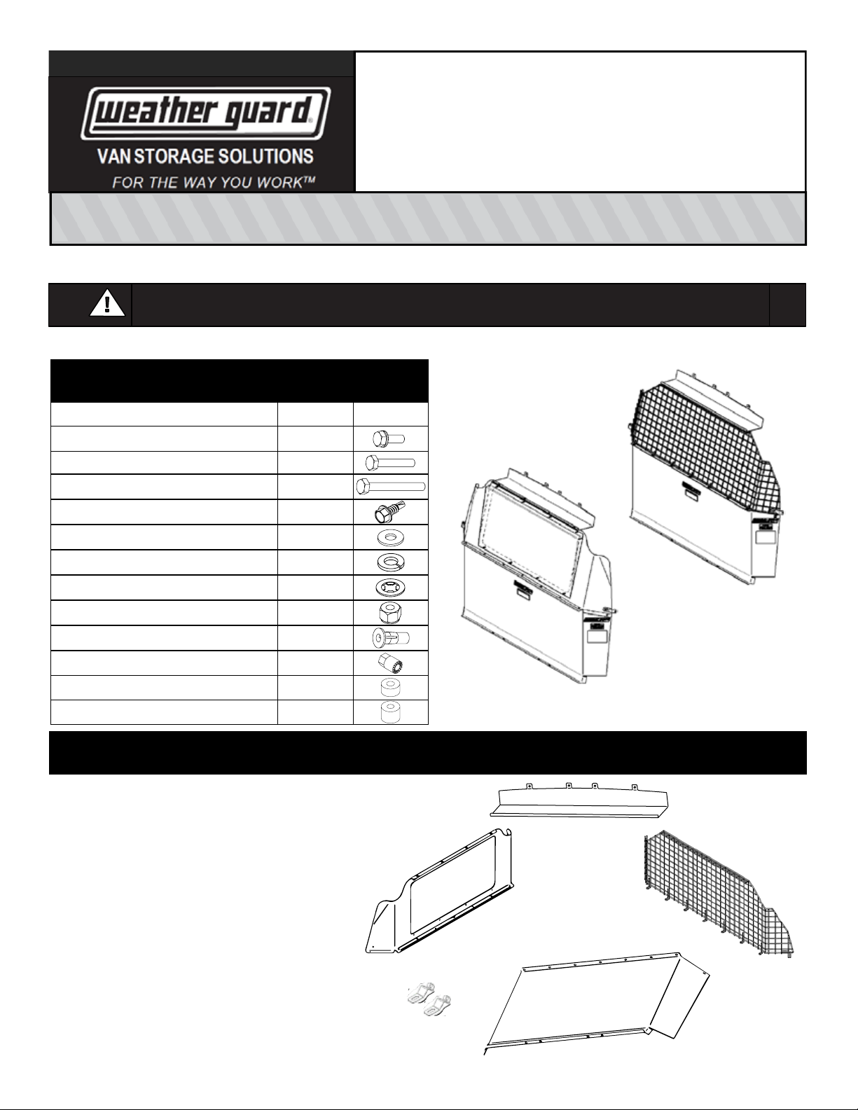
These instructions are to be followed using the parts and fasteners supplied for proper installation. Any modifications or improper installation of this
product will create a hazardous condition that could result in death, serious personal injury and/or property damage.
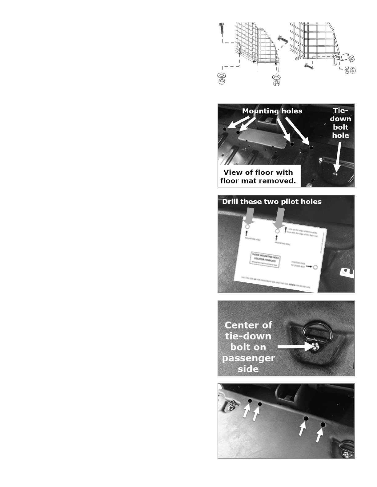
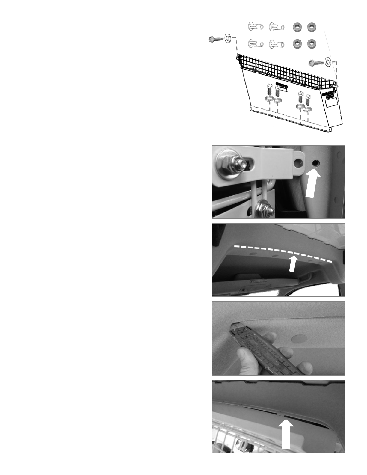
Prior to drilling, so as nottocut electric wires, fuel lines, brake lines, etc., check behind and underneath drilling and mounting locations.
To keep debris out of your eyes when checking the underside of the vehicle, or when drilling, always wear protective eye wear. Failure to
heedthis warning will result in death or serious injury.
WARNING
CAUTION
This manual suits for next models
1
Other Weather Guard Automobile Accessories manuals

Weather Guard
Weather Guard 1345-52-02 User manual

Weather Guard
Weather Guard 9444-3-01 User manual

Weather Guard
Weather Guard 1175 02 Series User manual

Weather Guard
Weather Guard 237 Instruction manual

Weather Guard
Weather Guard 238 Instruction manual

Weather Guard
Weather Guard ASRC001 User manual

Weather Guard
Weather Guard PowerSync User manual

Weather Guard
Weather Guard ITEMIZER 314 Instruction manual

Weather Guard
Weather Guard 234-3-01 User manual