manuals.online logo
Brands
  1. Home
  2. •
  3. Brands
  4. •
  5. Weber mt
  6. •
  7. Construction Equipment
  8. •
  9. Weber mt CF 1 Setup guide

Weber mt CF 1 Setup guide

SERVICE INFORMATION
Section 3*** Page 1
Service Information 2006
Repair Instructions CF 1
SERVICE INFORMATION
Section 3*** Page 2
Service Information 2006
Repair Instructions CF 1
Table of Contents
Illustration ..................................................................................................3
Preface .......................................................................................................4
1. Disassembly .....................................................................................5
2. Reassembly .................................................................................... 11
SERVICE INFORMATION
Section 3*** Page 3
Service Information 2006
Repair Instructions CF 1
Indicates important information and hints which must be followed by the operator and service personnel.
Indicates working and operating methods requiring in addition the observance of all applicable
environment protection and waste disposal regulations.
Indicates working and operating methods which must be precisely followed in order to prevent the soil
compactor from being damaged or deteriorated.
Indicates working and operating methods which must be precisely followed in order to avert direct danger
to persons.
Preface
Before starting your repair work, carefully read these repair instructions. Carefully follow all instructions and always
carry out the described operations in the indicated order.
The safety precautions prescribed for repair work must be followed in order to avert injury to persons and/or damage
to material property.
For safety reasons, any modifications and retrofittings made on the soil compactor without the manufacturer's
authorization are prohibited. Damage resulting from modifications or retrofittings is excluded from the manufacturer's
liability. Only use genuine WEBER spare parts to ensure a safe and reliable operation.
Important information is highlighted by the pictograms explained in the following. Please strictly observe the
information given in the repair instructions.
SERVICE INFORMATION
Section 3*** Page 4
Service Information 2006
Repair Instructions CF 1
shaft
tapered roller bearing
shaft seal
washer
guard
V-belt pulley
bearing cover
plug
cover
shim
eccentric
O-ring
seal
Illustration
O-ring
seal
SERVICE INFORMATION
Section 3*** Page 5
Service Information 2006
Repair Instructions CF 1
1
V-belt guard
1. Disassembly
Undo the fastening screws (2) to remove the V-belt
guard (1).
Undo the fastening screws (1) of the engine (2) and
push the engine to the front.
Remove the V-belt (1).
Undo the 4 fastening screws (1) of the engine bracket
and take off the complete upper part.
Figure 1
Figure 2
Figure 3
Figure 4
1
2
1
2
1
SERVICE INFORMATION
Section 3*** Page 6
Service Information 2006
Repair Instructions CF 1
Figure 4 a
Figure 5
Figure 6
Put the base plate (1) with integrated vibrator (2) at an
appropriate place.
Slightly tilt the base plate (1) with integrated vibrator (2)
and remove the oil drain screw (3).
Danger to the Environment!
Choose a drain pan having a sufficient
capacity to catch all the used oil. Do not let
used oil run into the soil. Dispose of the
collected used oil in an environmentally-
friendly manner (acc. to statutory pollution
control regulations).
Wipe up any oil and dispose of the oil-
soaked cloth in an environmentally-friendly
manner.
Protect the base plate against slipping - risk
of injury!
Undo the two fastening screws (2) and remove the V-
belt guard (1).
1
2
3
1
2
1
SERVICE INFORMATION
Section 3*** Page 7
Service Information 2006
Repair Instructions CF 1
Figure 7
Figure 8
Figure 9
Remove the fastening screw (1) of the V-belt pulley (2).
Screw a hexagon socket screw (1) in the eccentric shaft
to protect the thread.
Put the extractor (1) between the two flanks of the V-belt
pulley (2) and remove the V-belt pulley from the
eccentric shaft by means of the extractor.
Take care that the extractor does not slip off the
flanks - risk of injury!
1
2
1
1
2
SERVICE INFORMATION
Section 3*** Page 8
Service Information 2006
Repair Instructions CF 1
Figure 10
Figure 11
Figure 12
Remove the 4 fastening screws (1) of the housing cover
(2).
Use appropriate screw drivers or fitting levers and press
the housing cover (1) from the vibrator housing.
Be careful not to damage the sealing surface.
Remove the 4 fastening screws (1) of the housing cover
(2).
1
2
1
2
1
2
SERVICE INFORMATION
Section 3*** Page 9
Service Information 2006
Repair Instructions CF 1
Figure 13
Figure 14
Figure 15
Use appropriate screw drivers or fitting levers to remove
the housing cover (1) from the vibrator housing (2).
Take the eccentric (1) out of the vibrator housing.
Put the extractor (1) against the bearing (2) and remove
the bearing.
At first, insert an appropriate screw to protect the
female thread of the eccentric shaft.
Take care that the extractor cannot slip - risk of
injury!
1
2
1
Clamp the eccentric (3) in a vise.
2
3
1
SERVICE INFORMATION
Section 3*** Page 10
Service Information 2006
Repair Instructions CF 1
Put the extractor (1) against the bearing (2) and remove
the bearing.
Figure 16
Take care that the extractor cannot slip - risk of
injury!
Clamp the eccentric in a vise (3).
1
3
2
SERVICE INFORMATION
Section 3*** Page 11
Service Information 2006
Repair Instructions CF 1
2. Reassembly
Figure 17
Figure 18
Figure 19
Clamp the eccentric shaft in a vise. Use an
appropriate tool and carefully knock the bearing (1)
onto the shaft.
Use an appropriate tool (2) to drive the outer ring (1)
of the bearing into the housing cover (3).
Fit the shaft seal (1) into the housing cover.
1
2
3
1
2
1
2
SERVICE INFORMATION
Section 3*** Page 12
Service Information 2006
Repair Instructions CF 1
Figure 20
Figure 21
Figure 22
Apply grease onto the O-ring seal (1) of the housing
cover (2).
Use an appropriate tool (2) to drive the outer ring (1) of
the bearing into the vibrator housing (3).
Fit the housing cover (1).
1
2
1
2
3
1
SERVICE INFORMATION
Section 3*** Page 13
Service Information 2006
Repair Instructions CF 1
Figure 23
Figure 24
Figure 25
Put the eccentric (1) into the vibrator housing (2).
Put the housing cover (1) with the shaft seal (2) onto the
vibrator housing.
The cast characters (3) must face upwards.
Use an appropriate tool to fit the housing cover (1) onto
the vibrator housing (2).
1
2
3
1
2
1
2
SERVICE INFORMATION
Section 3*** Page 14
Service Information 2006
Repair Instructions CF 1
Figure 27
Figure 26
Figure 28
Fasten the housing (1) with 2 screws (2) at the top.
Fit the V-belt pulley (1) together with the retaining ring
(2) and the fastening screw (3) onto the eccentric shaft.
The fastening screw (3) must feature a vent hole
in order to ensure the pressure compensation in
the vibrator housing.
Fit the V-belt guard (1).
1
2
1
2
3
1
SERVICE INFORMATION
Section 3*** Page 15
Service Information 2006
Repair Instructions CF 1
Figure 29
Figure 30
Figure 31
Use an appropriate tool (2) to fit the eccentric shaft
(1) without play.
Use an appropriate tool to fit the bearing's outer ring (1)
without play.
Fit the O-ring seal (1) onto the housing cover (2).
1
2
1
2
1
2
SERVICE INFORMATION
Section 3*** Page 16
Service Information 2006
Repair Instructions CF 1
Figure 32
Figure 33
Figure 34
Spread the O-ring seal (1) with grease.
Use a depth slide gauge (1) to determine the distance
between the cover's collar (2) and its upper surface (3).
Measure the depth between the housing (1) and the
bearing outer ring (2).
1
1
2
3
1
2
SERVICE INFORMATION
Section 3*** Page 17
Service Information 2006
Repair Instructions CF 1
Figure 35
Figure 36
Figure 37
Adjust the axial play by means of the shim ring (1) .
Axial play 0.45 mm.
Fit the housing cover (1) .
Characters faced upwards.
Top the system up with oil according to the operating
instructions manual.
Check to ensure that the contact surfaces of
the oil filler/drain screw and of the vibrator
housing are clean.
Danger to the environment!
Immediately wipe up any escaping oil,
dispose of oil-soaked cloth in an
environmentally-friendly matter.
1
1
SERVICE INFORMATION
Section 3*** Page 18
Service Information 2006
Repair Instructions CF 1
Slightly knock on the V-belt pulley (1) to drive in the
eccentric shaft again.
Check the axial play as shown.
Figure 38
Figure 39
1

Other Weber mt Construction Equipment manuals

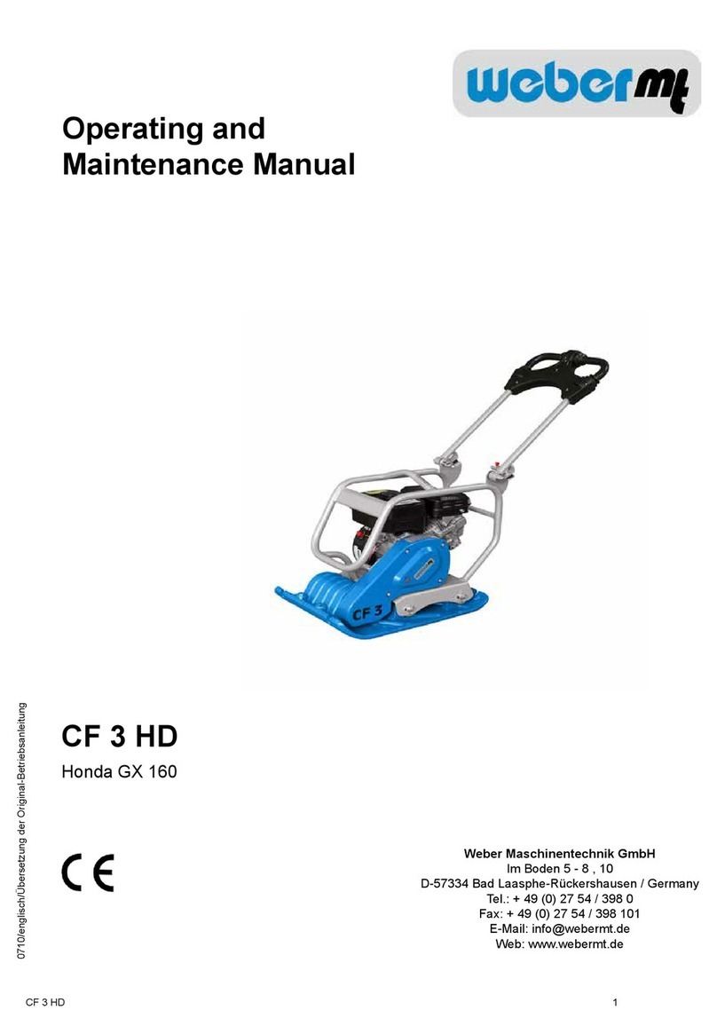
Weber mt CR 3 Operating and installation instructions

Weber mt

Weber mt CR 3 Operating and installation instructions

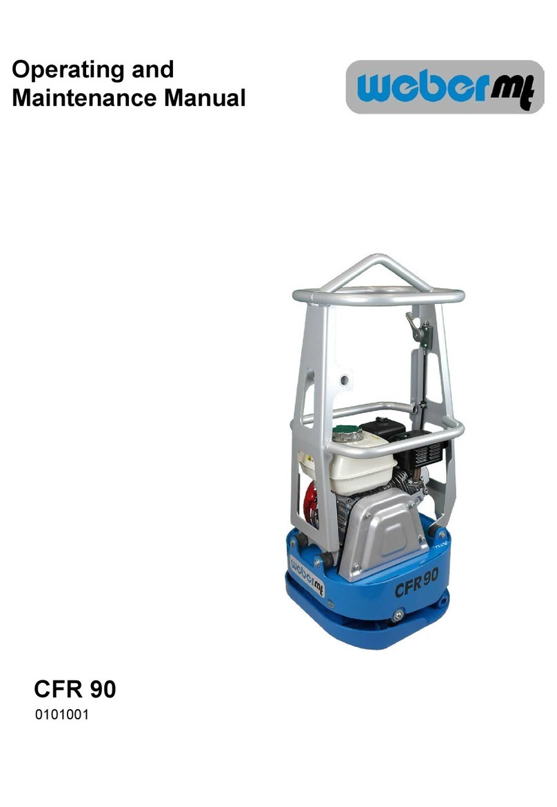
Weber mt CFR 90 Operating instructions

Weber mt

Weber mt CFR 90 Operating instructions

Weber mt MC 85 Operating instructions

Weber mt

Weber mt MC 85 Operating instructions

Weber mt DVH 550 L - 2 Operating instructions

Weber mt

Weber mt DVH 550 L - 2 Operating instructions

Weber mt CF 3 R Operating instructions

Weber mt

Weber mt CF 3 R Operating instructions

Weber mt CF 3 HD Operating instructions

Weber mt

Weber mt CF 3 HD Operating instructions

Weber mt CR 8 MDM Operating instructions

Weber mt

Weber mt CR 8 MDM Operating instructions

Weber mt CR 2 DC Operating instructions

Weber mt

Weber mt CR 2 DC Operating instructions

Weber mt CFR 90 DC Operating instructions

Weber mt

Weber mt CFR 90 DC Operating instructions

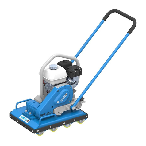
Weber mt VPR 450 Operating instructions

Weber mt

Weber mt VPR 450 Operating instructions

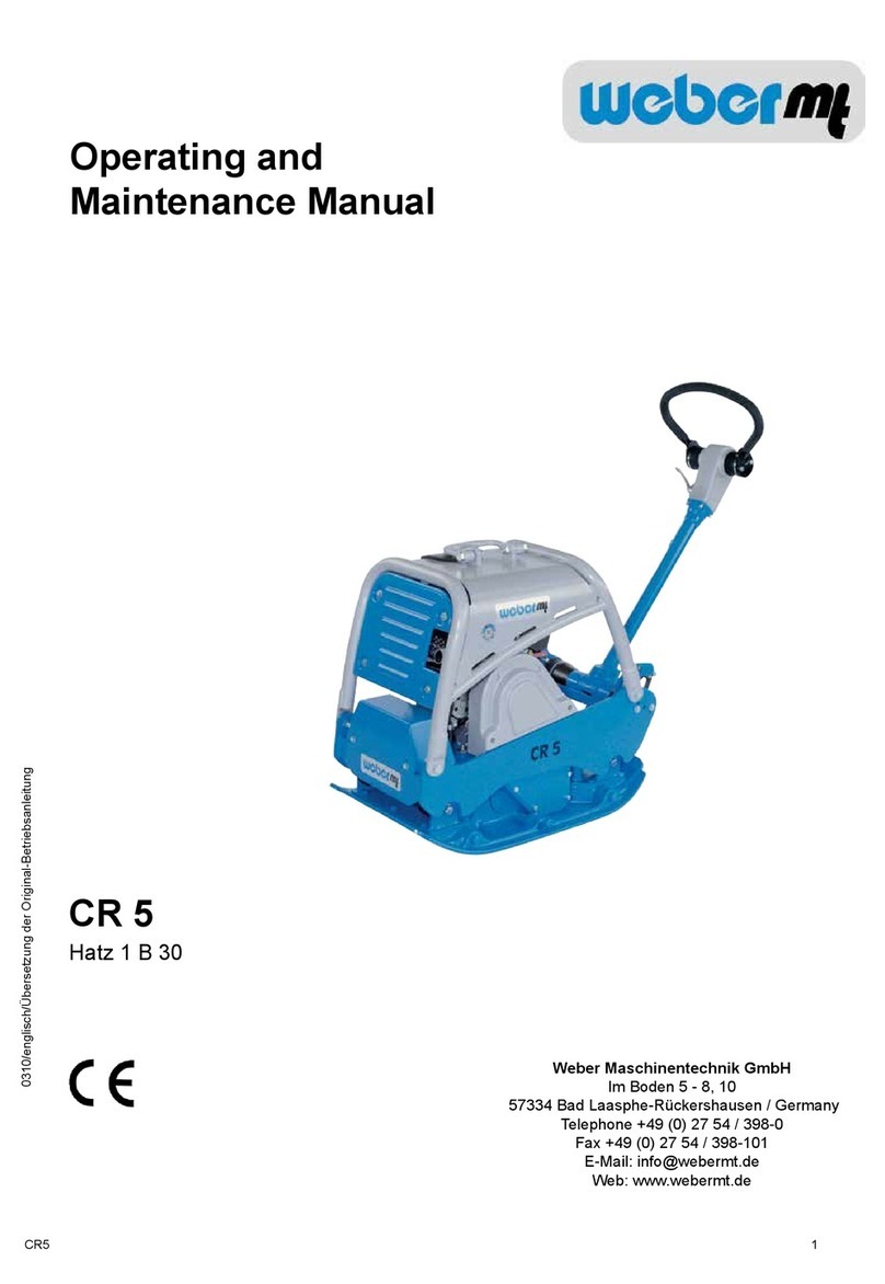
Weber mt CR 5 Operating instructions

Weber mt

Weber mt CR 5 Operating instructions

Weber mt IVURplus 40 D Operating instructions

Weber mt

Weber mt IVURplus 40 D Operating instructions

Popular Construction Equipment manuals by other brands

LeeBoy Rosco Maximizer 4B Safety and operation manual

LeeBoy

LeeBoy Rosco Maximizer 4B Safety and operation manual

Fluid Management H-1 Operating and instruction manual

Fluid Management

Fluid Management H-1 Operating and instruction manual

ENAR QX Series instruction manual

ENAR

ENAR QX Series instruction manual

Case 1150M Service manual

Case

Case 1150M Service manual

Vestil HOP-LP instruction manual

Vestil

Vestil HOP-LP instruction manual

stellar labs 15000 owner's manual

stellar labs

stellar labs 15000 owner's manual

STEINEL PROFESSIONAL HG 2620 E Information

STEINEL PROFESSIONAL

STEINEL PROFESSIONAL HG 2620 E Information

hymer 6472 Instructions for use

hymer

hymer 6472 Instructions for use

Altrad BELLE MINIMIX 150E+ Operator's manual

Altrad

Altrad BELLE MINIMIX 150E+ Operator's manual

Genie 360 Z135 Tech tips

Genie 360

Genie 360 Z135 Tech tips

Husqvarna Soff-Cut 2000 Operator's manual

Husqvarna

Husqvarna Soff-Cut 2000 Operator's manual

Werk-Brau D-Lock Coupler Installation and operation manual

Werk-Brau

Werk-Brau D-Lock Coupler Installation and operation manual

HYVA HB100 WARNING, OPERATING AND MAINTENANCE MANUAL

HYVA

HYVA HB100 WARNING, OPERATING AND MAINTENANCE MANUAL

Red Rhino 5000 PLUS Series Operation & Maintenance Handbook

Red Rhino

Red Rhino 5000 PLUS Series Operation & Maintenance Handbook

Benchmark HCM400 manual

Benchmark

Benchmark HCM400 manual

Graco 231-132 Instructions-parts list

Graco

Graco 231-132 Instructions-parts list

Dynapac CA250 i instruction manual

Dynapac

Dynapac CA250 i instruction manual

Case 2050M Tier2 Service manual

Case

Case 2050M Tier2 Service manual

manuals.online logo
manuals.online logoBrands
  • About & Mission
  • Contact us
  • Privacy Policy
  • Terms and Conditions

Copyright 2025 Manuals.Online. All Rights Reserved.