Deutsch | 7
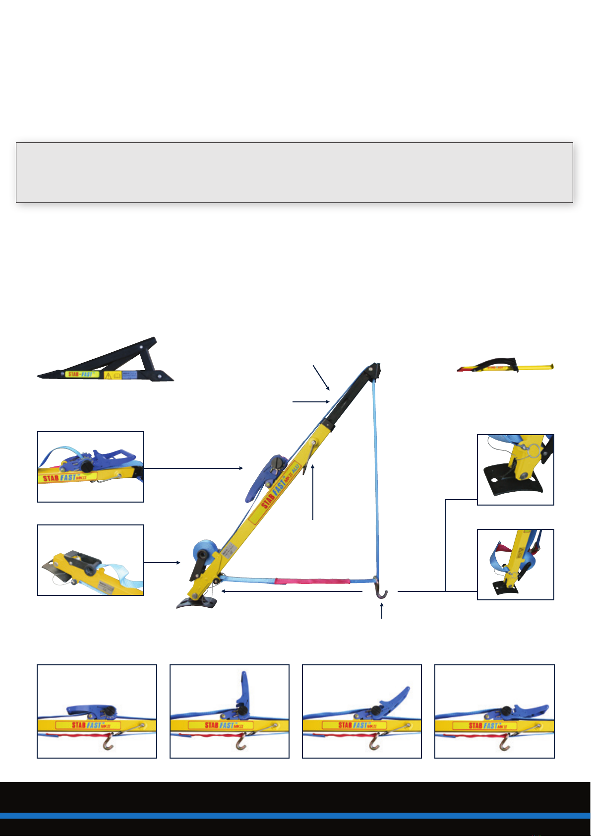
Schwerpunkte beim Einsatz
ACHTUNG
Bei der Rettung des Opfers muss die Stabilisierung ständig kontrolliert werden. Achten Sie dabei auf:
1. Die Spannung der Kraftbänder, wenn nötig, nachspannen.
2. Mögliches Verschieben des Stabilisierungsstützkopfes. Wenn nötig, den Kopf der Stützes mit einer
Leine an einem festen Teil des Fahrzeugs sichern.
3. Einsinken oder Weggleiten der Stabilisierungsstütze-Basis.
4. Ein Verschieben des verstellbaren Keils.
5. Die Befestigung des Spitzhakens am Fahrzeug.
Nach dem Einsatz
1. Bänder mit der Ratsche entspannen (Stellung 3).
ACHTUNG
Bei einem auf dem Dach liegenden Fahrzeug beide Seiten gleichzeitig entspannen.
2. Teleskopelemente einschieben.
3. Bänder mithilfe des Aufrollmechanismus aufwickeln.
4. Beim Einpacken kontrollieren, ob der Satz wieder komplett ist.
5. Satz reinigen und überprüfen, wie in dem Kapitel “Wartung und Inspektion – Nach jedem Gebrauch”
beschrieben.
Stabilisierung eines auf der Seite liegenden Fahrzeugs
1. Die 1. Stabilisierungsstütze mit dem grünen Kraftband vorne an der Unterseite des Fahrzeugs (Motorseite)
anbringen. Stabilisierungsstütze soweit wie möglich ausfahren. Spitzhaken möglichst niedrig am Fahrzeug
einhaken, dabei den Haken nicht an beweglichen Teilen wie Stützbeinen, Tragarmen usw. befestigen.
ACHTUNG
Platzieren Sie eine Schutzplatte aus Holz zwischen dem möglicherweise heißen Auspuff und dem Kraftband. Rote
Schutzhülle vor möglicherweise scharfe Teile schieben. Kraftband mit Ratsche anziehen, bis es gespannt ist.
ACHTUNG
Darauf achten, dass sich das Fahrzeug beim Spannen nicht neigt.
2. Die 2. Stabilisierungsstütze mit dem gelben Kraftband vorne an der Oberseite des Fahrzeugs (Motorhaube)
anbringen. Stabilisierungsstütze soweit wie möglich ausfahren, mit dem Spitzhaken an einem möglichst tiefen
Punkt am Fahrzeug befestigen oder mit dem Hebelmesser einen möglichst tiefen Schnitt in der Motorhaube
anbringen*. Spitzhaken in den Schnitt einhaken. Rote Schutzhülle vor möglicherweise scharfe Teile schieben.
Kraftband mit Ratsche anziehen, bis es gespannt ist.
*HINWEIS
Motorhaube nach Möglichkeit zuerst öffnen und einen festen Punkt für das Einhaken des Spitzhakens suchen.
3. Beide Seiten weiter spannen. Kontrollieren, ob beide Kraftbänder gespannt sind.
ACHTUNG
Fahrzeug nicht anheben.
4. Die 3. Stabilisierungsstütze mit dem blauen Kraftband hinten an der Unterseite des Fahrzeugs anbringen.
Kraftband von der Unterseite der Stabilisierungsstütze lösen. Loses Band durch die Rolle in der Nase des
verstellbaren Keils führen. Kraftband wieder an der Unterseite der Stabilisierungsstützes befestigen.
ACHTUNG
Die Kraftbandsicherung kontrollieren. Den verstellbaren Keil an der Rückseite (Kofferraumseite) unter dem
Fahrzeug platzieren.
ACHTUNG
Platzieren Sie eine Schutzplatte aus Holz zwischen dem möglicherweise heißen Auspuff und dem Kraftband.
Rote Schutzhülle vor möglicherweise scharfe Teile schieben. Kraftband spannen, bis das Fahrzeug etwas auf
den verstellbaren Keil gezogen wird.
5. Jetzt ist das Fahrzeug stabilisiert.