Metacon-Next RGT EW 60-90 User manual

User Manual
Metacon-Next RGT EW 60-90
Metacon-Next
Zuidbaan 450
2841 MD Moordrecht
The Netherlands
Tel. : +31 (0) 182 510 777
www.metacon-next.com
info@metacon-next.com
Metacon-Next
Randweg 19
8304 AS Emmeloord
The Netherlands
Tel. : +31 (0) 527 610 824
www.metacon-next.com
info@metacon-next.com

Metacon-Next OHD-C EI(1) 60 / EI(2) 90 / EW 90 18-05-2021
User manual art nr: 89022 Rev: 2
2
1Foreword................................................................................................................................................. 3
2Introduction.............................................................................................................................................4
3Safety ...................................................................................................................................................... 4
3.1 Safety devices .................................................................................................................................. 5
3.2 Safety instructions............................................................................................................................ 5
3.3 Residual risks ................................................................................................................................... 6
4Instructions for use..................................................................................................................................6
4.1 Normal use (not during fire alarms/emergencies) ............................................................................. 6
4.2 Self-closing function ......................................................................................................................... 7
4.3 Actions after improper use ............................................................................................................... 7
5Technical specifications ........................................................................................................................... 7
6Product....................................................................................................................................................8
7Installation preparations..........................................................................................................................8
7.1 Essential tools for installation........................................................................................................... 8
8Installation instructions ...........................................................................................................................9
9First use ................................................................................................................................................. 31
10 Maintenance, malfunctions and repairs................................................................................................. 31
10.1 Regular maintenance ..................................................................................................................... 31
10.2 Cleaning......................................................................................................................................... 31
10.3 Malfunctions and repairs................................................................................................................ 31
11 Storage and transport............................................................................................................................ 32
12 Environment and disposal...................................................................................................................... 32
Annex A: “OHD-C EI(1) 60 / EI(2) 90 / EW 90” - Technical information........................................................... 33
Annex B: “OHD-C EI(1) 60 / EI(2) 90 / EW 90” - Maintenance instructions".................................................... 34
Annex C: “OHD-C EI(1) 60 / EI(2) 90 / EW 90” - Log......................................................................................... 35

Metacon-Next OHD-C EI(1) 60 / EI(2) 90 / EW 90 18-05-2021
User manual art nr: 89022 Rev: 2
3
1Foreword
Before using the door, please observe the safety and operating instructions listed in this
document.
Metacon only supplies products to "specialist retailers". This means that Metacon only
supplies a door and the installation is carried out by and under the responsibility of the
"specialist retailer".
If assembly and installation are carried out by a third party and the control unit is provided
by the installation company, the manufacturer of the fire shutter door will issue a CE
declaration in accordance with current European legislation.
It is the responsibility of the installation company to install the door in accordance with the
manual. The user manual must remain with the door at all times.
The type plate with the serial number is attached in the following location: On the drive side
on the guide, about 1600 mm from the bottom. This sticker must not be removed or
covered.
Metacon cannot be held liable for any unsafe situations, accidents, damage and injuries, for
example, resulting from:
Ignoring warnings or instructions displayed on the fire door and/or in the user
manual.
Insufficient and/or incorrect maintenance.
Changes to the fire door and accessories by third parties. This includes the
use of replacement parts other than those prescribed (e.g. a battery),
incorrect connection or adjustment, changing the controller and control
program.
Improper installation or assembly of the product.
Local (country-specific) additional regulations.
Reference documents:
NEN-EN 13241-1; NEN-EN 16034.
Terms and Conditions of the Metaalunie.
Installation Drawing Metacon.
Packing list with article numbers (spare parts list).
User manuals from the suppliers of motors and controllers for adjusting the
supplied drive and/or controller.

Metacon-Next OHD-C EI(1) 60 / EI(2) 90 / EW 90 18-05-2021
User manual art nr: 89022 Rev: 2
4
User manual of any accessories supplied.
DoP (Declaration Of Performance).
The installation company must follow all the guidelines in the assembly instructions.
The user must follow all the instructions in the user manual. The user manual must
be handed over to the user upon delivery to be left with the door.
© COPYRIGHT
Metaalwarenfabriek Metacon B.V. holds the copyright for this manual. All
worldwide rights reserved. Copying, translating, editing or saving this manual or
parts thereof on an electronic medium is not permitted without the prior written
permission of the copyright holder.
2Introduction
This fire-resistant door is mainly intended to separate connected spaces (fire compartments)
in case of fire and/or smoke development. The purpose of this is to prevent the fire from
spreading to other areas and/or adjacent premises. The fire shutter door can be controlled
by a fire alarm system, but can also be controlled by a "stand-alone" alarm system.
The CE marking issued is only valid for the performance mentioned in the Declaration Of
Performance (DoP).
In accordance with the NEN-EN 12635 standard, this document will cover the installation
instructions and instructions for first use following the user instructions.
3Safety
When installing the fire door, the (safety) rules applicable to the situation must be observed,
e.g. the Working Conditions Act. In addition to the regulations, the instructions in this
document should be strictly followed. When installing electrical components, the
instructions supplied by the manufacturer of these components must be observed.
As Metacon is only a manufacturer/supplier of "semi-finished products", it is the
responsibility of the installer to work according to the relevant rules.
The manufacturer of the fire door cannot be held liable for any damage or injury resulting
from non-compliance with this user manual or the maintenance instructions, or from
improper use.

Metacon-Next OHD-C EI(1) 60 / EI(2) 90 / EW 90 18-05-2021
User manual art nr: 89022 Rev: 2
5
3.1 Safety devices
The installation may be equipped with the following safety devices. Refer to the product
specifications in Section 5 for the installed devices.
Roll-off / fall protection / slack cable protection / pinch protection / switching
protection.
Smoke and temperature detectors and/or fire alarm system (BMI).
Shielding below 2500 [mm] from an accessible floor, mandatory in case of a crushing
hazard (NEN-EN 294).
ATEX components, if used in potentially explosive atmospheres.
3.2 Safety instructions
The fire shutter door is designed in such a way that the door will always close in case
of fire or a smoke alarm. The possible presence of persons is therefore not taken into
account. (Exceptions to this are possible in consultation with or after approval by the
competent authority; the installing party or (end) user must arrange this approval.)
If the door is installed in an escape route, ensure that the door is suitable for its
intended use (escape door). (EN 16034-2) (EN 14351-1 and 2)
When using a deadman’s control system, the control switch must be positioned in
such a way that the operator has a clear view of the opening/closing of the door.
Before operating, check that there is no visible damage to the door. If any damage is
found, the supplier must be asked to repair the damage. A door that is damaged
must not be operated.
During operation, check that there are no persons within ±2 [m] of the door.
The door may only be operated by persons who have familiarised themselves with
the operating instructions. Under no circumstances shall the door be operated by
children or persons with an impaired physical, sensory or mental condition. The door
may only be used in the manner described in paragraph 4.1.
Check that there are no obstacles under the roller shutter when closing.
During maintenance/inspection of the fire door, the system must be powered down.
Avoid trapping persons in the room. If anyone is still present, the door must remain
open.
If a failsafe drive is used, the door will close when the mains power and any back-up
battery are switched off; if the back-up battery is not switched off, the door will close
when the critical voltage is reached.
The entire installation should preferably be earthed (guide and bracket plates); this is
mandatory for an ATEX model.

Metacon-Next OHD-C EI(1) 60 / EI(2) 90 / EW 90 18-05-2021
User manual art nr: 89022 Rev: 2
6
3.3 Residual risks
Regular use:
Entrapment may occur when the fire shutter door closes during a fire alarm. The
automatic function of the fire door does not take into account the possible presence
of persons. The risk of a person getting caught is very low due to the low speed of the
closing movement.
When using a gravitational self-closing (failsafe) system on our products/fire doors,
two optional optical/acoustic signalling devices will be supplied in accordance with
the NEN EN 12604-2000 standard based on EN 13241-2016. Regardless of whether
these are supplied with the door, it is mandatory to install them at the door.
It is strictly forbidden to place any goods/materials in the "barrel" of the closing and/or
opening door leaf.
In case of maintenance:
The system must be powered down during maintenance/inspection. Voltages in the
installation leave a risk of electric shock.
When inspecting the movement system, a crushing hazard may occur when the door
is in motion.
4Instructions for use
4.1 Normal use (not during fire alarms/emergencies)
Before and during operation of the door, the following steps must be observed:
Before being allowed to operate the door, you must have read the safety instructions
in Section 3.
Check that there is nothing or nobody around, against or underneath the door while
operating the door; do not start or stop operating the door immediately if this is the
case.
Operate the door by means of the control element, usually push buttons or a key
switch. While operating the door, keep a sufficient distance from the moving part of
the door: 2-8 metres.
Make sure that, while operating the door, it actually moves in the correct direction. If
this is not the case, stop operating it or push and/or press the stop button and
immediately contact the supplier.
Keep an eye on the door at all times during movement.
Make sure the door is fully opened when opening and fully closed when closing to
maximise the service life of the door.
The door can be protected against entrapment of objects and/or persons in various ways.

Metacon-Next OHD-C EI(1) 60 / EI(2) 90 / EW 90 18-05-2021
User manual art nr: 89022 Rev: 2
7
When using a deadman’s control system, the door will stop immediately after
releasing the control element.
If there is a safety edge, the door will automatically go up again after contact with an
object and/or person.
Optionally, a photocell can be added to the safety edge function.
If a set of light strips is installed, the door will not close in this case if the sensor
detects an object in the path of this safety device. Please note that this only works in
the line/area of the safety sensor. An object and/or person is detected outside of
this.
Please note that safety devices are not designed to operate the door!
To put the door back into operation after the safety edge/light strip has been triggered,
please remove the objects and/or persons from the detection area of the safety devices.
4.2 Self-closing function
If the door is in the open position at the time it is "controlled" by an (automated)
detection/alarm system and mains power failure, it will close automatically. This is done by
means of an electric drive with a gravitational failsafe system. A gravitational failsafe system
means that the door can still close by gravity if the electrical equipment fails/cuts out. This
movement is controlled by a speed limiter. When being "controlled", the door will not take
into account any objects/persons underneath the door and will close immediately. As an
optional extra, the safety light strip can be kept temporarily active and closed with a forced
closure after a set time.
It is strictly forbidden to place any goods/materials in the "operating zone" of the closing
and/or opening door leaf.
4.3 Actions after improper use
If an object has become trapped under the door and the door has come to a standstill as a
result, perform the following actions:
Move the door up a little bit, so you can remove the object.
After the object has been removed, close the door completely! Before opening the
door.
Should one of these actions fail, please contact the supplier.
5Technical specifications
Please refer to the order confirmation and/or packing slip.

Metacon-Next OHD-C EI(1) 60 / EI(2) 90 / EW 90 18-05-2021
User manual art nr: 89022 Rev: 2
8
6Product
See the product leaflet and the optional BOM (Bill Of Materials) for this.
7Installation preparations
Before the installation of the door can be started, the following things must be checked:
Before proceeding with the installation, the installer must have taken note of the
contents of this user manual.
It is the responsibility of the installer to be aware of the local regulations concerning
the installation of the door (e.g. Working Conditions Act).
Check that the work area is accessible and has enough space for working, then
cordon off the work area. Pay attention to the following points:
-Check the clear width and height and the available side and top space; the
dimensions according to the order are leading.
-Check the mounting surface for obstacles.
-Check that the surface is flat before mounting.
-Check that the walls, floor and lintel are perpendicular and straight.
-Check that the correct electrical connections are in place.
-Assess whether the surface offers sufficient strength for the structure;
contact the client when in doubt about this.
Check all parts using the packing slip and/or order confirmation, and/or refer to the
list of all parts using the optional BOM (Bill of Materials) in the user manual.
7.1 Essential tools for installation
The required tools cannot be determined by Metacon, as this depends on the installation
situation. It is up to the installer to determine the suitable tools.

Metacon-Next OHD-C EI(1) 60 / EI(2) 90 / EW 90 18-05-2021
User manual art nr: 89022 Rev: 2
9
8Installation instructions
When the installer has prepared itself in accordance with Section 7, the installation of the
door can start.
Important: Fasteners are supplied as an option. Only use fasteners that are suitable for the
intended strength and smoke/fire resistance, and are suitable for the surface in question.
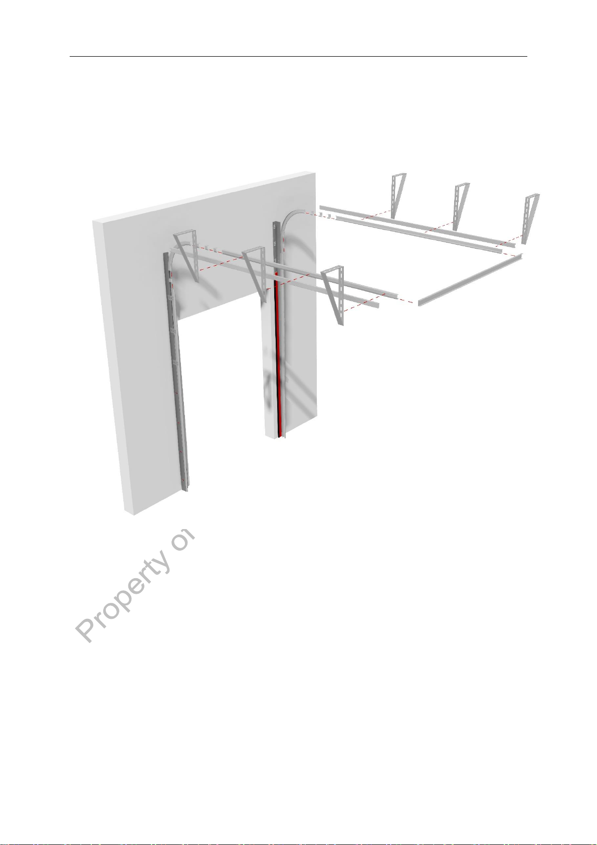
Step 1 - Mounting tracks
Mount the tracks widthwise according to Metacon Installation Drawing. Check the
width size. Check that the tracks are mounted parallel and level.
Metacon-Next OHD-C EI(1) 60 / EI(2) 90 / EW 90 18-05-2021
User manual art nr: 89022 Rev: 2
10
Step 2a - Mounting tracks (horizontal fitting)
Mount the door suspension system. Make sure that theguide pieces areplaced
perpendicular and parallel. Mount the spacer at the rear of the horizontal
track!
Metacon-Next OHD-C EI(1) 60 / EI(2) 90 / EW 90 18-05-2021
User manual art nr: 89022 Rev: 2
11
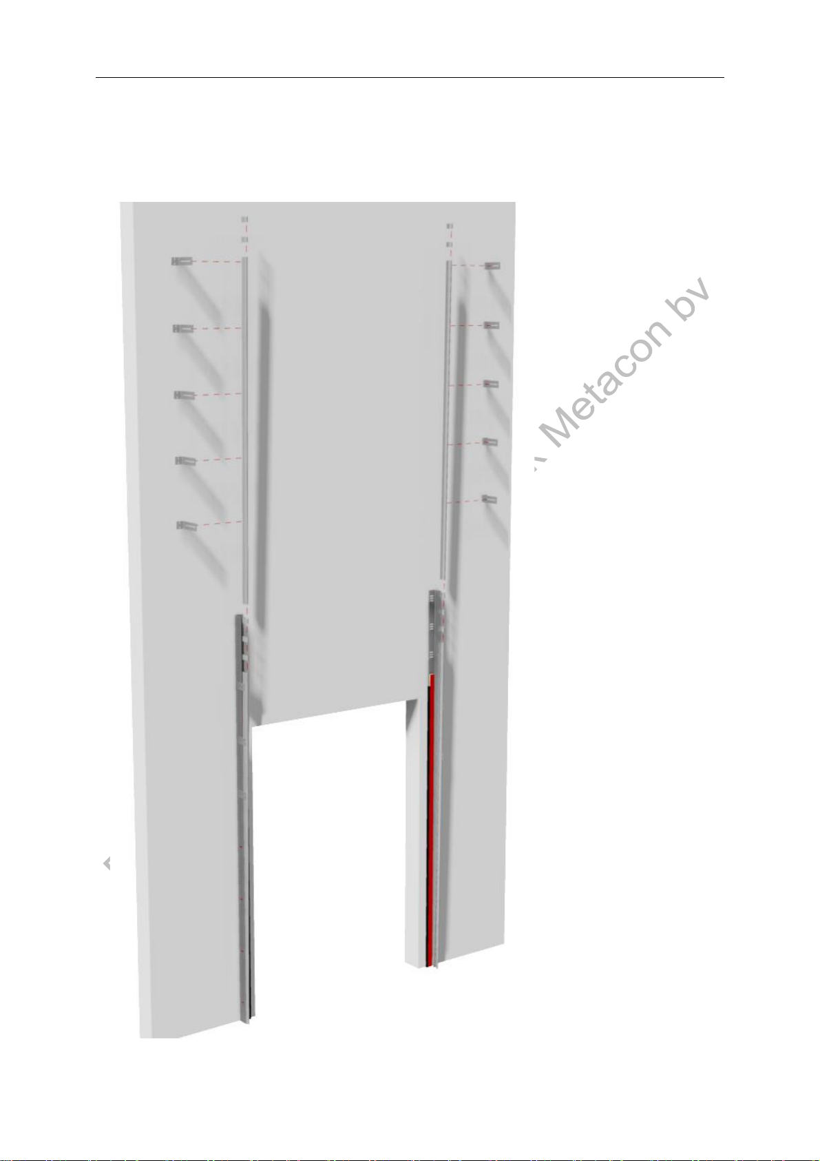
Step 2b (alternative to 2a) - Mounting tracks (vertical fittings)
In case of a vertical lifting door mount the upper part of the track. Check that
the tracks are mounted parallel and level.
Metacon-Next OHD-C EI(1) 60 / EI(2) 90 / EW 90 18-05-2021
User manual art nr: 89022 Rev: 2
12
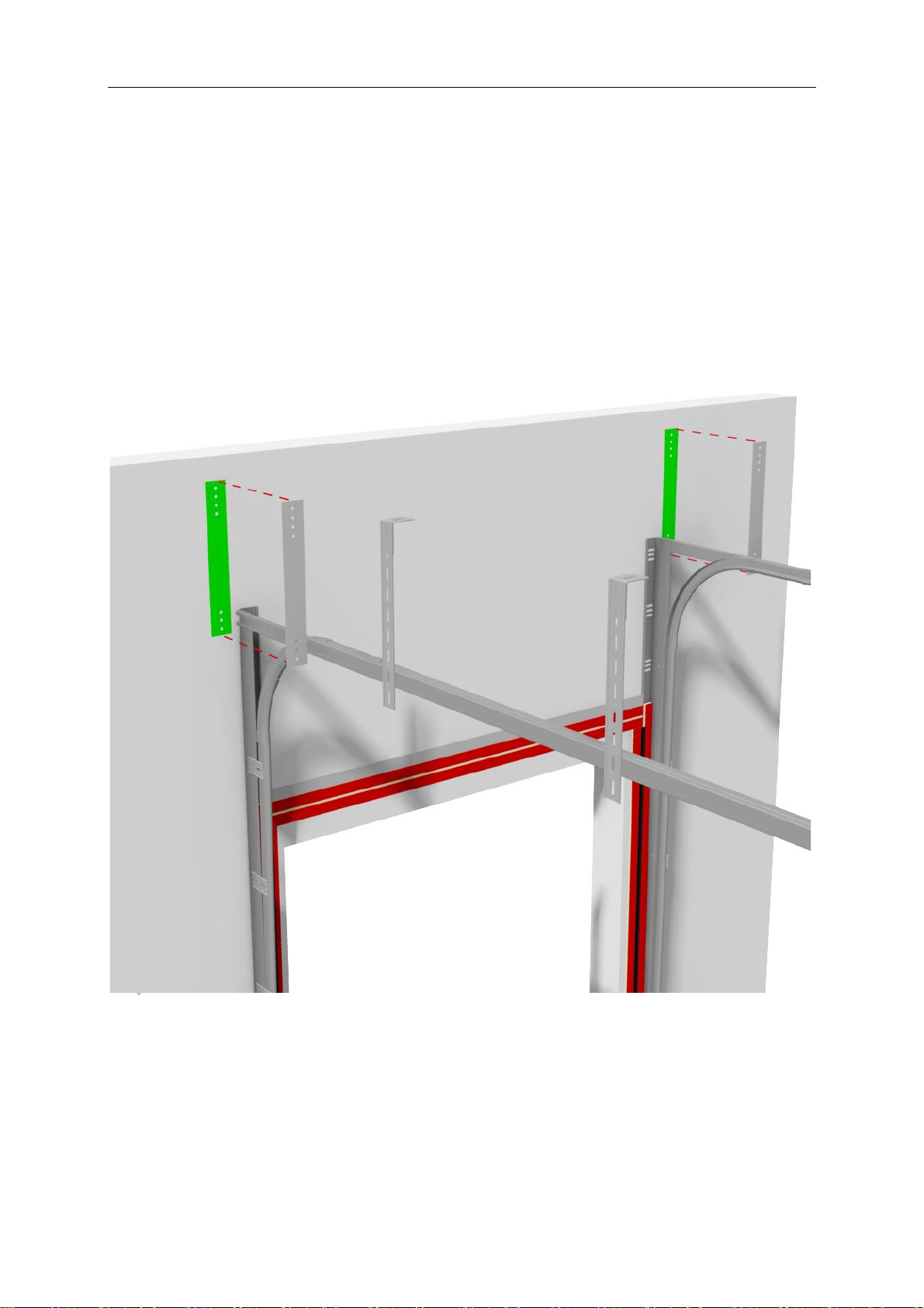
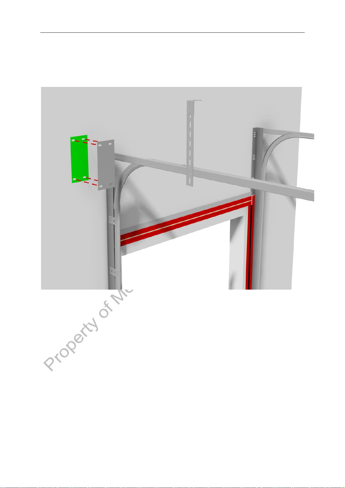
Step 3 - Mounting wall hook
Mount the wall hook at the correct height according to Metacon Installation
Drawing. Make sure that the space between the wall hook and the left and right
guides is equal.

Metacon-Next OHD-C EI(1) 60 / EI(2) 90 / EW 90 18-05-2021
User manual art nr: 89022 Rev: 2
13
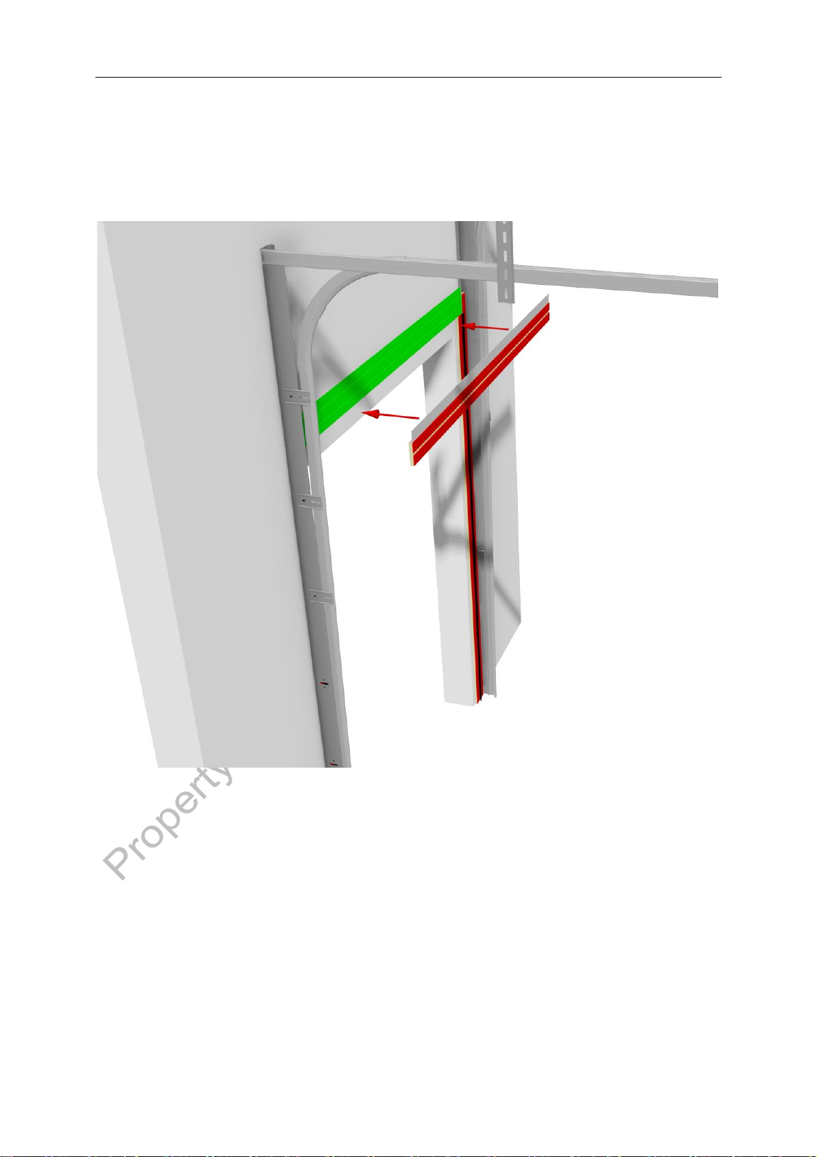
Step 3b - Mounting vertical mazes
Mount the vertical mazes widthwise according to the Metacon Installation
Drawing. Check the width size. Check that the vertical mazes are parallel and
level.
Metacon-Next OHD-C EI(1) 60 / EI(2) 90 / EW 90 18-05-2021
User manual art nr: 89022 Rev: 2
14
Step 4a - Use of drilling jig consoles & motor slide
Place the drilling jigs according to Metacon Installation Drawing. Check that it
is level, mark the hole pattern and remove the drilling jigs. To ensure it is
securely fastened, use at least 3 mounting holes per console (2 above and 1
below the horizontal beam). Then drill the holes, taking into account the
required distance and depth of the fasteners.
Metacon-Next OHD-C EI(1) 60 / EI(2) 90 / EW 90 18-05-2021
User manual art nr: 89022 Rev: 2
15
Place the drilling jig for the motor slide as shown below, mark the hole pattern
and remove the drilling jig. To ensure it is securely fastened, use all mounting
holes. Then drill the holes, taking into account the required distance and depth
of the fasteners.

Metacon-Next OHD-C EI(1) 60 / EI(2) 90 / EW 90 18-05-2021
User manual art nr: 89022 Rev: 2
16
Step 4b - Mounting of consoles (wall mounting)
Mount the consoles according to the Metacon Installation Drawing. Make sure
the consoles are level, parallel and perpendicular to the wall.
Step 4c - Mounting consoles (ceiling mounting)
Mount the consoles according to the Metacon Installation Drawing. Make sure
the consoles are level, parallel and perpendicular to the wall.

Metacon-Next OHD-C EI(1) 60 / EI(2) 90 / EW 90 18-05-2021
User manual art nr: 89022 Rev: 2
17
Step 5a - preparation for drive shaft assembly
Degrease and oil the axle journals before mounting the bearings on them.
Slide the safety brake over the axle journal by rotating in the right direction with key.
PLEASE NOTE: Check that the safety brake is not blocked. If it is blocked, it must be
unblocked! See safety brake on data sheet for further instructions.
Place the bearing over the axle journal on the other side.
Tighten 1 locking screw of the bearing by hand to prevent it from sliding off.
Note: The figure below refers to a situation where the drive is located on the left.
Step 5b: Mount the sprocket
On the motor side, insert the key into the axle journal. Then slide the sprocket on with the
hub pointing in the opposite direction of the roll.
Metacon-Next OHD-C EI(1) 60 / EI(2) 90 / EW 90 18-05-2021
User manual art nr: 89022 Rev: 2
18
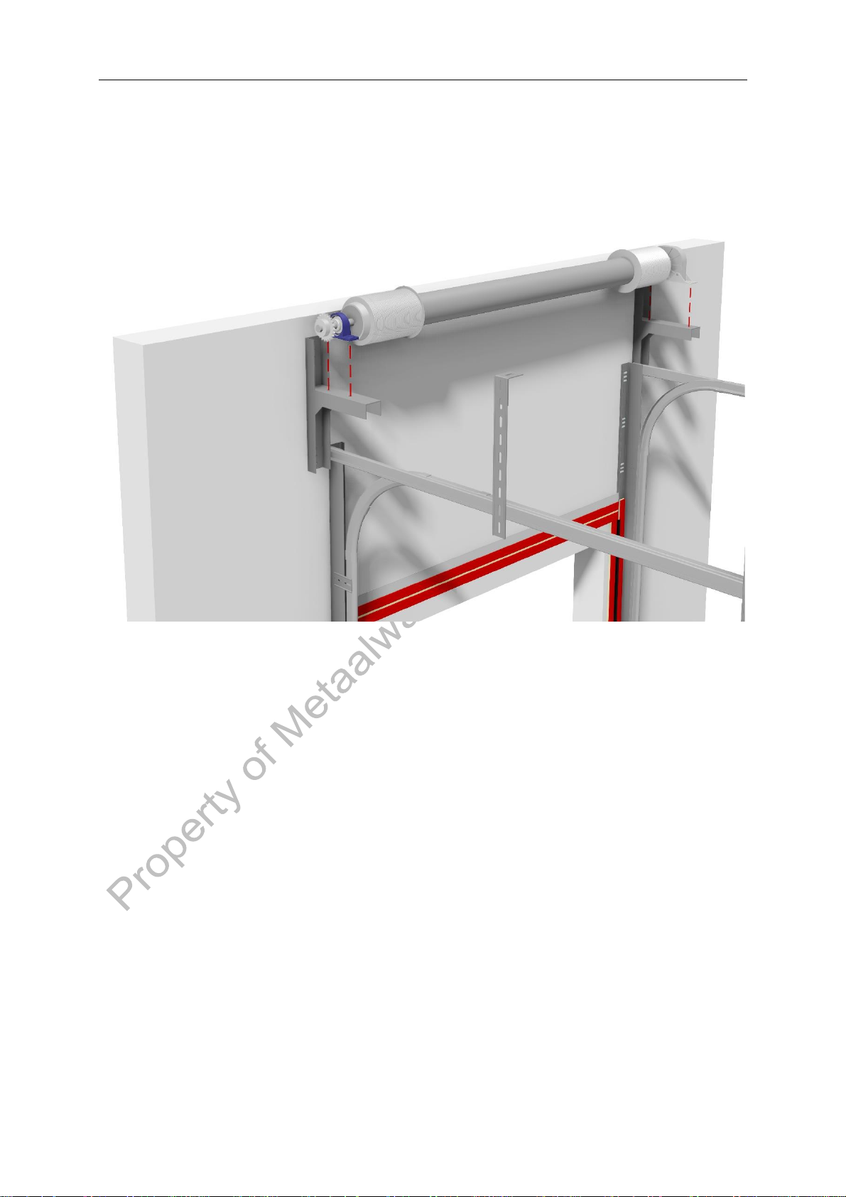
Step 5c - Drive shaft assembly
Check that the shaft is mounted parallel to the wall. Make sure that the space
between the cable drums and left and right tracks is equal. Tighten the bolts
and the locking screws of the bearings.

Metacon-Next OHD-C EI(1) 60 / EI(2) 90 / EW 90 18-05-2021
User manual art nr: 89022 Rev: 2
19
Step 5b - Mounting motor slide & chain drive motor
Mount the motor slide.
Check that the housing of the limit switch is in the correct position, it must not
be in contact with the chain.
Mount the control box and connect it to the power supply including the battery
if included as well as the safety brake.
Please note: any other components may only be connected at step 11 of
this manual!
Check that the direction of rotation corresponds to the buttons in the control
box at the connection to which the door is to be adjusted.
Place the sprocket on the axle journal, with the hub pointing towards the
engine.
The motor can now be mounted on the motor slide with the fasteners (as
provided) in the middle position of the range of adjustment of the motor slide.
Align sprockets both horizontally and vertically and secure with the locking
screws.
Metacon-Next OHD-C EI(1) 60 / EI(2) 90 / EW 90 18-05-2021
User manual art nr: 89022 Rev: 2
20
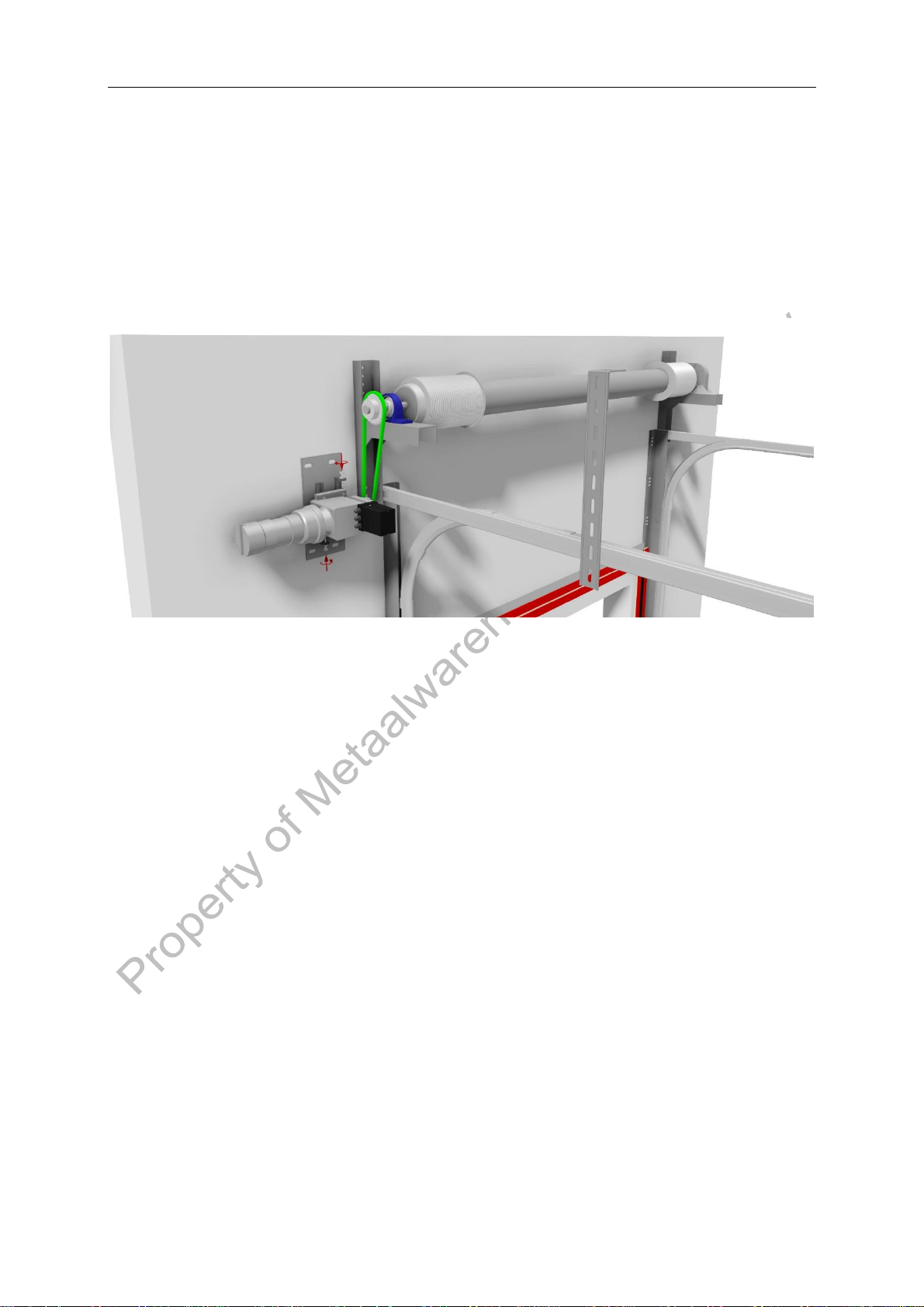
Step 5c - Mounting and tensioning chain
Lay the chain around the sprockets, mark the required length and loosen the chain.
Shorten the chain to the required length and lay it around the sprockets using the
supplied fasteners.
When tensioning the chain, make sure that it is not too tight.
If the chain tension is insufficient, the safety brake may be activated by the excess of
space on the chain.
After tensioning the chain, check that the sprockets are still correctly aligned.
Table of contents
Other Metacon-Next Safety Equipment manuals


Popular Safety Equipment manuals by other brands


ALL WEATHER ACCESS
ALL WEATHER ACCESS EuroMat Information sheet

EUCHNER
EUCHNER CES-AZ-UBS-01B operating instructions

Robur
Robur 8147P Instructions for use

bolle SAFETY
bolle SAFETY B809 quick start guide

Assa Abloy
Assa Abloy 179A Mounting instruction

Liteplan
Liteplan CE1S/2W/M3 Series Assembly instructions