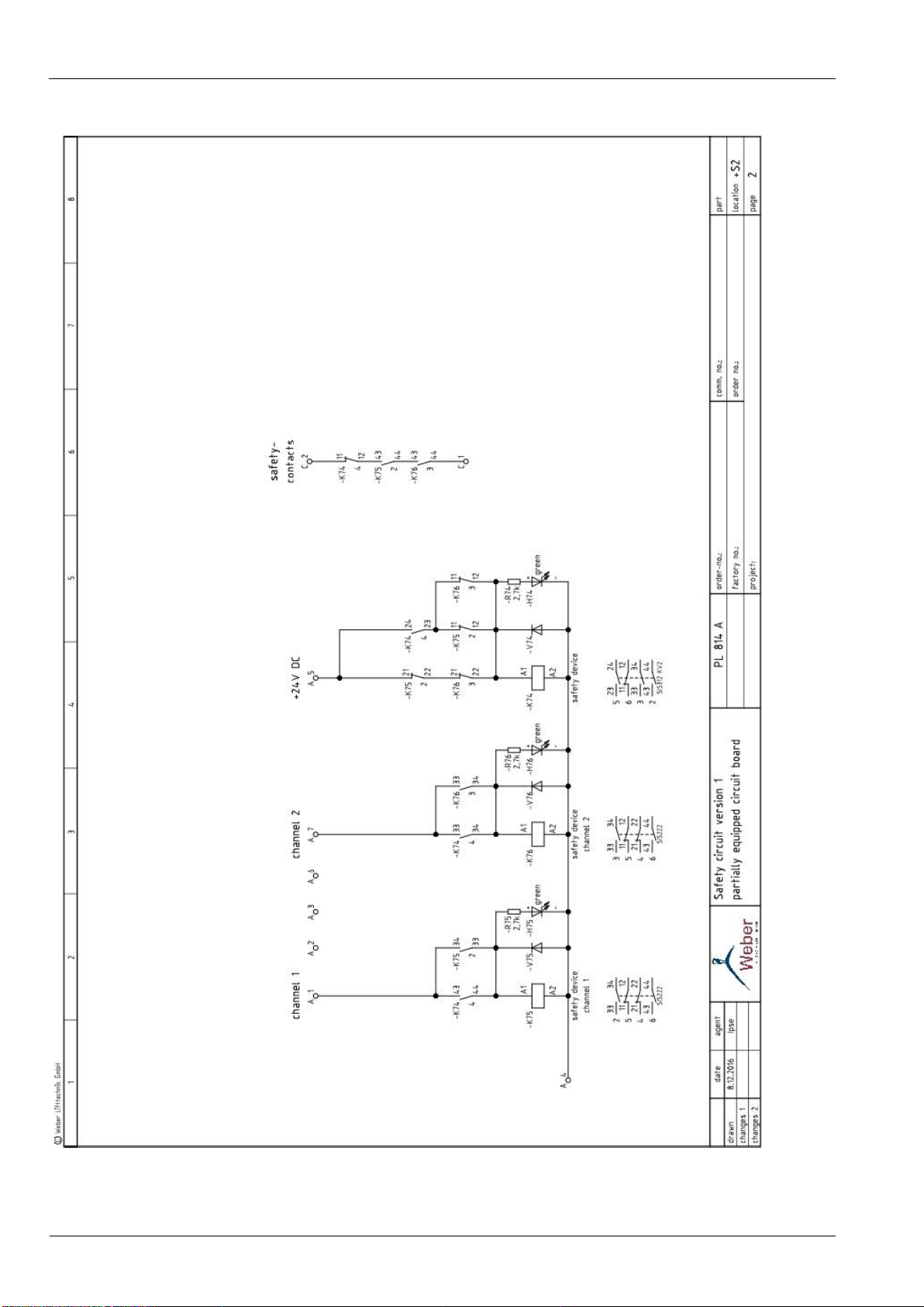
3.3. Safety device PL814 version 2 for approach and re-adjustment with open doors
See circuit diagram: “6.3. Safety device PL814 version 2”
See circuit diagram: “7.2. Shaft copying”
See function description of the safety device: “3.1. Safety device version 1”
If approach or readjustment should be possible with open doors, the completely equipped
circuit board PL814 bridges the door switch and the switch for the locking mechanism in the lift
control units by Weber Lifttechnik GmbH.
The relay –K73 (connection terminal A2) is activated via a control unit output as soon as the
control unit and the absolute encoder for the shaft copying system are ready for operation. It
remains energised as long as operational readiness remains. A contact for this relay prevents
the safety relay of the second channel –K76 being activated, as long as the control unit and
therefore the input signal for the first channel –K75 are not ready for operation. The second
contact is available potential-free, for example, in order to activate the UCM-monitoring circuit
board PL751A only after achieving readiness for operation.
A further control unit output supplies an enable signal for the relay -K60, if the following
conditions are fulfilled:
a. The approach or readjustment procedure should be executed.
b. The travel speed has the permitted values (slow, under 0.3 m/s) as in EN81, for
approach and readjustment procedures.
In case of hydraulic lifts or unregulated traction elevators without impulse generators for
position recording, a speed measurement is not possible. The enable then occurs after
switching to slow speed.
If the conditions for the relay –K60 are fulfilled, on reaching the door zone configured on the
control unit the safety relay -K75 (channel 1) is activated via the control unit output “Readjust
(door zone)”. –K75 remains energised, as long as the lift car is positioned within the door zone.
This door zone signal is provided by a transducer, e.g. absolute encoder or magnetic or
electronic adjustment switches which are connected to the control computer.
The second safety relay -K76 (channel 2) is activated directly via a switch in the door zone,
e.g. magnetic switch. It energises as soon as the door zone switched is actuated and the
abovementioned enable relays -K60 and –K73 are energised. It then remains switched on until
the lift leaves the door zone again.
As soon as the two relays -K75 and -K76 are energised, -K74 is de-energised. As a result, the
shunt circuit of the door switch and the switch of the locking mechanism between the
connection terminals C1 and C2 are closed and the door may open.
As soon as the lift leaves the door zone, the two relays -K75 and -K76 de-energise and -K74
can energise. Should -K74 not energise, then the two relays -K75 and -K76 remain de-
energised on approaching the target stop, and therefore the bridging of the door switch and
the switch for the locking mechanism are opened.